Table of Contents
Advertisement
Quick Links
BOSS PRODUCTS NORTH AMERICAN
SUPPLEMENTAL MANUAL FOR
ECOMAXX NO RETURN VALVE (EM-NRV)
PAGE 2 -
PAGE 3 -
PAGE 4 -
PAGE 5 -
PAGES 6 THRU 8 -
PAGE 9 -
PAGE 10 -
PAGE 11 -
PAGES 12 THRU 13 --
PAGES 14 THRU 17 --
PAGES 18 THRU 20 -
PAGES 21 THRU 22 -
PAGES 23 THRU 24 -
PAGE 25 -
PAGE 26 -
PAGE 27 -
PAGE 28 -
INFO@BOSSPRODUCTSAMERICA.COM - WWW.BOSSPRODUCTSAMERICA.COM
TABLE OF CONTENTS
INTRODUCTION / WARRANTY
SUPPLEMENTAL MANUAL INFORMATION
ECOMXX EM-NRV SPECIFICATIONS
O-EM-NRV-CP02 SPECIFICATIONS
INSTALLING THE MICROSWITCH - O-EM-NRV-MS
INSTALLING THE DUST LEVEL SENSOR - O-EM-NRV-DLS
WIRING PANEL O-EM-NRV-CP02 TO MAIN CONTROL PANEL
120VAC INPUT POWER WIRING
EM-NRV PRODUCT GROUP SPARE PARTS
CONTACT INFORMATION
Advertisement
Table of Contents

Related Manuals for Boss Ecomaxx


Summary of Contents for Boss Ecomaxx
-
Page 1: Table Of Contents
BOSS PRODUCTS NORTH AMERICAN SUPPLEMENTAL MANUAL FOR ECOMAXX NO RETURN VALVE (EM-NRV) TABLE OF CONTENTS PAGE 2 – INTRODUCTION / WARRANTY PAGE 3 – SUPPLEMENTAL MANUAL INFORMATION PAGE 4 – SAFETY PAGE 5 – NFPA COMPLIANCE PAGES 6 THRU 8 –... - Page 2 ECOBOSS Line of Energy Management Control Systems WARRANTY: Boss Products, LLC warrants to the Buyer that the material sold to Buyer will be free from manufacturing defects at the time of shipping of such material to the job site. Boss Products, LLC further warrants to the Buyer that the workmanship and material...
- Page 3 THIS MANUAL IS A SUPPLEMENT TO THE AIRCOM INSTALLATION, USE AND MAINTENANCE MANUAL FOR NO RETURN VALVES. IT HAS BEEN COMPILED BY BOSS PRODUCTS, LLC FOR THE NORTH AMERICAN MARKET THE INSTALLER AND END USER MUST BE FAMILIAR WITH BOTH, THE AIRCOM MANUAL AND BOSS PRODUCTS SUPPLIMENT ...
-
Page 4: Safety
Page 4 of 28 SAFETY ELECTRIC SHOCK HAZARD ONLY QUALIFIED PERSONELL SHOULD INSTALL, MAINTAIN OR WORK ON THIS EQUIPMENT! ALWAYS PERFORM WORK WITH THE POWER OFF! ARC FLASH HAZARD APPROPRIATE PPE REQUIRED! FOLLOW ALL REQUIREMENTS IN NFPA 70E ALWAYS MAINTAIN PROPPER CONVEYING VELOCITIES AS REQUIRED BY NFPA 652 &... -
Page 5: Nfpa Compliance
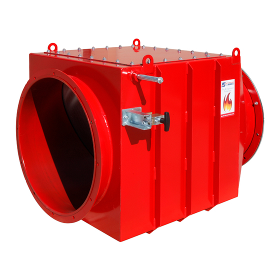
Page 5 of 28 NFPA COMPLIANCE NFPA 652 – STANDARD ON THE FUNDAMENTALS OF COMBUSTIBLE DUST – 2016 EDITION 8.9.4 – Equipment Isolation o 8.9.4 – Where an explosion hazard exists, isolation devices shall be provided to prevent deflagration propagation between connected equipment in accordance with NFPA 69. - Page 6 Page 6 of 28 ECOMAXX EM-NRV NO RETURN VALVE SPECIFICATIONS STANDARD FEATURES (ALL SIZES) Heavy Duty Welded Steel Construction * Epoxy Powder Coated Safety Red Finish Flanged Inlet and Outlet with Co-Flanges * Grounding Lugs * Locking Mechanism(s) ATEX Certification ...
- Page 7 Page 7 of 28 EM‐NRV DUCTWORK OF SUFFICIENT NO RETURN VALVE STRENGTH TO WITHSTAND THE PEAK EXPLOSION PRESSURE* DUST COLLECTOR DISTANCE ** *NFPA 69-2014 (A.12.2.3.4.6) STATES: The minimum design pressure for the ductwork is typically 2 x P because the pressure wave reflects off the closed valve. Depending on the distance between the flap valve and the enclosure, pressure piling could further increase the expected peak pressure.
- Page 8 Page 8 of 28 DIMENSIONS FOR SIZES 32” THRU 40” Model ᴓ EM-NRV32 31.49” / 800mm 38.5 40.1 52.3 56.4 25.9 25.9 18.8 28.1 14.1 EM-NRV36 35.43” / 900mm 42.5 44.4 56.2 60.4 27.9 27.9 20.8 27.9 14.1 EM-NRV40 39.37”...
- Page 9 Page 9 of 28 ECOMAXX O-EM-NRV-CP02 INTRINSIC PANEL SPECIFICATIONS 4 Models Available* Model: O-EM-NRV-CP02 (1 NRV) Model: O-EM-NRV-CP02X2 (Up-to 2 NRVs) Model: O-EM-NRV-CP02X3 (Up-to 3 NRVs) Model: O-EM-NRV-CP02X4 (Up-to 4 NRVs) *Larger Panels are available on request All Models Feature the following:...
-
Page 10: Receiving The Ecomaxx Em-Nrv
RECEIVING THE ECOMAXX EM-NRV The EcoMAXX EM-NRV typically ships shrink-wrapped and strapped on a wooden pallet. Customer must inspect the equipment for damage upon receipt. If damage is present, receiver must note damaged on the shipping documents in order to file a claim. -
Page 11: Assembly Instructions (Sizes 7" Thru 10")
Page 11 of 28 ASSEMBLY INSTRUCTIONS (SIZES 7”-10”) No Return Valve Sizes 7”-10” have a locking arm without a counterweight and come assembled as shown in the above picture. For mounting the microswitch and dust level sensor, refer to pages 18-22. ... -
Page 12: Assembly Instructions (Sizes 12" Thru 28")
Page 12 of 28 ASSEMBLY INSTRUCTIONS (SIZES 12”-28”) Counter Weight Locking Mechanism Manual with Metric Allen Wrench EM-NRV NORTH AMERICAN SUPPLEMENTAL MANUAL - V2016NRV-ELE... - Page 13 Page 13 of 28 Remove Bolt on Counter Weight Mounting Shaft Using Provided Allen Wrench. Slide Counter Weight onto Shaft as Shown Position Counter Weight in the Locked Position in the Locking Mechanism. Tighten the Two Bolts to Clamp Counter Weight in Place.
-
Page 14: Assembly Instructions (Sizes 32" Thru 40")
Page 14 of 28 ASSEMBLY INSTRUCTIONS (SIZES 32”+) Breaking Elements Locking Mechanism Counter Weight (Upper Section) Manual with Metric Allen Wrenches Counter Weight Arm (Lower Section) EM-NRV NORTH AMERICAN SUPPLEMENTAL MANUAL - V2016NRV-ELE... - Page 15 Page 15 of 28 Counter Weight Arm (Lower Section) **NOTE** Lower Section may be Installed at Factory and This Step May not be Necessary. Remove Bolt and Washer and Slide Arm on to Shaft Slide Arm until it Fits over the Key Stop.
- Page 16 Page 16 of 28 Locking Mechanism, Counter Weight, and Breaking Element 1. Install Locking Mechanism onto mounting bracket of the EcoMAXX NRV. 2. Ensure handle is centered in the locking mechanism. If incorrectly installed, handle may rub or stick preventing the counter weight from locking in place during an event.
- Page 17 IMPORTANT!! Be sure to remove safety pin from counterweight! Failure to do so will cause the EcoMAXX No Return Valve to not close fast enough during an event. EM-NRV NORTH AMERICAN SUPPLEMENTAL MANUAL - V2016NRV-ELE...
- Page 18 Page 18 of 28 O-EM-NRV-MS (Microswitch) with Mounting Bolts 1. Remove screw and rotate lever to correct position 2. Line up arrows 3. Insert and tighten Screw EM-NRV NORTH AMERICAN SUPPLEMENTAL MANUAL - V2016NRV-ELE...
- Page 19 Page 19 of 28 Mounting O-EM-NRV-MS (Microswitch) to EcoMAXX No Return Valve 1. Mount microswitch to locking mechanism using provided bolts 2. Rotate counterweight arm into the locked position. Ensure arm is centered in the locking mechanism to avoid obstruction or rubbing. If not centered, the arm may not fully close or lock during an event.
- Page 20 Page 20 of 28 Wiring O-EM-NRV-MS (Microswitch) to O-EM-NRV-CP02 Intrinsic Panel 1. When looking at the wiring diagram you will notice only the black and grey wires are used for the microswitch connection. 3. Connect the grey wire to the terminal labeled 2 2.
- Page 21 Mounting O-EM-NRV-DLS (Dust Level Sensor) to EcoMAXX No Return Valve O-EM-NRV-DLS (Dust Level Senor) kit with drawing 1. Remove bolt on bottom side of the EcoMAXX No Return Valve (NRV) 2. Install first mounting nut 3. Insert on sensor. sensor into...
- Page 22 Page 22 of 28 Wiring O-EM-NRV-DLS (Dust Level Sensor) to O-EM-NRV-CP02 Intrinsic Panel 1. On the Wiring diagram you will notice the Dust Level Sensor will be installed inside the physical barrier in the control panel. 2. Connect brown wire to the 3.
- Page 23 Page 23 of 28 Wiring the EcoMAXX O-EM-NRV-CP02 Intrinsic Panel to your Main System Control Panel 1. On the wiring diagram you will notice there are two options provided to connect to the main system control panel. One is an individual alarm configuration and the other is a general alarm configuration.
- Page 24 Page 24 of 28 Wiring the EcoMAXX O-EM-NRV-CP02 Intrinsic Panel to your Main System Control Panel OPTION #2 1. Connect the low voltage control wire to the #3 and #6 terminals as described in option 1. Use a jumper to connect terminals #4 and #5.
- Page 25 Page 25 of 28 Wiring 120VAC Supply Power to the EcoMAXX O-EM-NRV-CP02 Intrinsic Panel 1. 120/1/60 supply power is required to power the panel. Connect to terminals as shown L / GND / EM-NRV NORTH AMERICAN SUPPLEMENTAL MANUAL - V2016NRV-ELE...
-
Page 26: General Wiring Diagram
Page 26 of 28 General Wiring Diagram for the EcoMAXX O-EM-NRV-CP02 Intrinsic Panel EM-NRV NORTH AMERICAN SUPPLEMENTAL MANUAL - V2016NRV-ELE... - Page 27 Flange P/N: EB-FLᴓ Other replaceable parts Co-Flange P/N: EB-CFLᴓ not noted may be available but must discussed with Boss Products to insure integrity and functionality Locking Mechanism with Mounting Bracket ...
-
Page 28: Box 953 - 33100 Ne Ivy Avenue - La Center, Wa 98629 - Usa
FIRE AND EXPLOSION PROTECTION SYSTEMS P.O.BOX 953 – 33100 NE IVY AVENUE - LA CENTER, WA 98629 – USA PH: 360-263-2360 – FAX: 360-263-9772 INFO@BOSSPRODUCTSAMERICA.COM – WWW.BOSSPRODUCTSAMERICA.COM © Boss Products, LLC 2016 EM-NRV NORTH AMERICAN SUPPLEMENTAL MANUAL - V2016NRV-ELE...