Advertisement
Quick Links
Advertisement

Related Manuals for Bosch D340


Summary of Contents for Bosch D340
- Page 1 Duct smoke housing, 2-wire D340/D340P Installation manual...
- Page 3 Install, test and maintain the module according to these instructions, NFPA codes, local codes, and the authority having jurisdiction (AHJ). Failure to follow these instructions can result in failure of a detector to initiate an alarm event. Bosch Security Systems, Inc. is not responsible for improperly installed, tested or maintained devices.
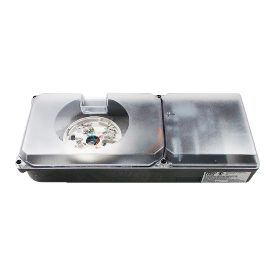
- Page 4 Description Overview The D340 Duct smoke housing is designed to mount to the ducts of heating, ventilation, and air-conditioning (HVAC) systems to monitor the presence of smoke in the conditioned air. It operates on a two‑wire loop, and requires a smoke detector head.
-
Page 5: Setting The Jumpers
(D344-RT keyswitch). The power off reset from the control panel zone functions normally regardless of the jumper setting. Notice! Disable the reset jumper whenever you are not using the D344-RT (D307). Bosch Security Systems, Inc. Installation manual 2017.04 | 7.0 | F.01U.071.685... - Page 6 | Description Duct smoke housing, 2-wire For enabled and disabled jumper positions, see the following figure. Figure 2.2: Jumper settings 1 Disabled 2 Enabled 2017.04 | 7.0 | F.01U.071.685 Installation manual Bosch Security Systems, Inc.
- Page 7 2 6 to 10 times the width oft he duct 3 Width of duct 4 Return air inlet The D340 can be mounted in any direction of 90° increments without regard to the air flow direction (see the following figure). Bosch Security Systems, Inc.
- Page 8 Use even spacing when covering the sample holes to allow an even sample across the width of the duct (see the following figure). Figure 3.4: Covering sample tube holes 2017.04 | 7.0 | F.01U.071.685 Installation manual Bosch Security Systems, Inc.
-
Page 9: Mounting The Detector
Seal the gap between duct and sample tube. You can remove up to 6 in. (15 cm) from the D344‑1.5 for 1 ft (0.3 m) duct installations. Mounting the detector Locate the D340 mounting template and remove it from its backing. Place the template over the desired location on the duct (see the following figure). Bosch Security Systems, Inc. - Page 10 Remove the screws for later use. Place the two foam gaskets over the sample and exhaust ports on the back of the housing (see the following figure). 2017.04 | 7.0 | F.01U.071.685 Installation manual Bosch Security Systems, Inc.
- Page 11 Figure 3.9: Mounting the housing 1 Duct 2 Housing 3 Machine screws (supplied) Determine and remove the appropriate wire knockouts for power and for any remote indicator wiring (see the following figure). Bosch Security Systems, Inc. Installation manual 2017.04 | 7.0 | F.01U.071.685...
- Page 12 10. Note the direction of the airflow in the duct. The sampling holes in the sample tube must face into the air flow (see the first figure below). The exhaust tube must exhaust downwind from the sample tube (see the second figure below). 2017.04 | 7.0 | F.01U.071.685 Installation manual Bosch Security Systems, Inc.
- Page 13 Ensure the tube alignment point set into the housing. 12. Secure the tubes in place using the tube clamps provided (see the following figure). Figure 3.14: Mounting tubes in housing Bosch Security Systems, Inc. Installation manual 2017.04 | 7.0 | F.01U.071.685...
- Page 14 13. Place the tube filters over the open ends of the sample and exhaust tubes (see the following figure). Figure 3.15: Tube filters 1 Exhaust tube 2 Sample tube 3 Housing 4 Tube filters 2017.04 | 7.0 | F.01U.071.685 Installation manual Bosch Security Systems, Inc.
- Page 15 Notice! Do not exceed 500 ft (152 m) between the D344-RT (D307) Remote test/indicator plate and the D340 housing. Use 18 AWG (ISO 0.75 mm ) or larger wire. Bosch Security Systems, Inc. Installation manual...
- Page 16 10 D344-RT (D307) Wiring to the D344-RL Notice! Do not exceed a distance of 500 ft (152 m) between the D344-RL (D306) Remote indicator plate and the D340. Use 18 AWG (ISO 0.75 mm ) or larger wire. 2017.04 | 7.0 | F.01U.071.685 Installation manual...
- Page 17 Wiring to the DRA-5 Notice! Do not exceed a distance of 500 ft (150 m) between the DRA-5 Remote indicator plate and the D340 housing. Use 18 AWG (ISO 0.75 mm ) or larger wire. Figure 4.4: D340 to DRA-5 wiring 1 Optional external power (24 VAC/VDC)
- Page 18 Connect the ground wire to the screw on the ground plate when using grounded three-wire AC wiring (see step 8 of the mounting procedure in Mounting the detector, page 9). Figure 4.6: Wiring D340 to FACP and external power 1 FACP 2 Alarm initiating loop 3 External power (24 VAC/VDC)
- Page 19 Place a magnet against the duct housing’s test point notch on the front cover (see the following figure). Figure 5.1: Testing the detector 1 Magnet 2 Test point notch 3 Detector 4 Housing Bosch Security Systems, Inc. Installation manual 2017.04 | 7.0 | F.01U.071.685...
-
Page 20: Maintenance
Notify all concerned parties before and after completing maintenance on or testing of the fire alarm system. Clean the detector and base annually using a vacuum or with clean, dry compressed air. 2017.04 | 7.0 | F.01U.071.685 Installation manual Bosch Security Systems, Inc. -
Page 21: Specifications
25% of DC input Power-up time 22 sec maximum Voltage, operating 8.5 VDC to 32 VDC from two-wire loop. Optional 24 VDC/VAC from control panel or external supply. D340 with D344-RT, D344-RL, and External Power Loop power External power 8.5 V to 32 V 24 V Condition –... - Page 22 18.9 in. x 7.5 in. X 7.8 in. (48 cm x 19 cm x 19.8 cm) (LxWxH) Product Dimensions (LxWxH) 15.5 in. x 4.3 in. x 6.5 in. (39.5 cm x 11 cm x 16.5 cm) Material High‑impact fire‑retardant polymer plastic Weight Gross 4.23 lb. (1.92 kg) 3.84 lb. (1.74 kg) 2017.04 | 7.0 | F.01U.071.685 Installation manual Bosch Security Systems, Inc.
- Page 24 Bosch Security Systems, Inc. Bosch Sicherheitssysteme GmbH 130 Perinton Parkway Robert-Bosch-Ring 5 Fairport, NY 14450 85630 Grasbrunn Germany www.boschsecurity.com © Bosch Security Systems, Inc., 2017...