Table of Contents
Advertisement
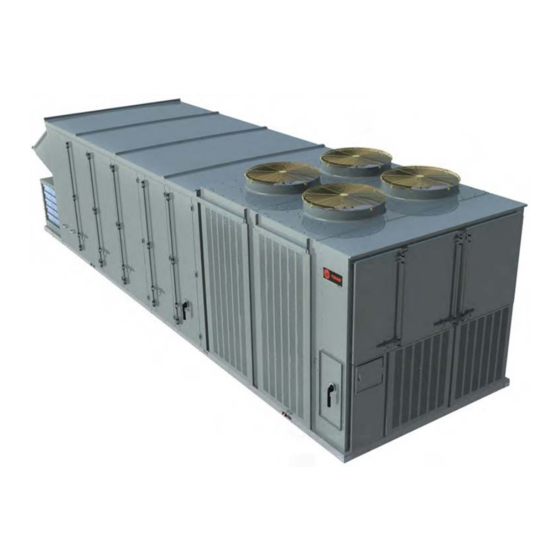
Installation, Operation, and Maintenance
IntelliPak™ ™ with Symbio™ ™ 800
Commercial Rooftop Air Conditioners
" " A A " " a a n n d d l l a a t t e e r r d d e e s s i i g g n n s s e e q q u u e e n n c c e e
R R A A *20, *25, *30, *40, *50, *55, *60,
*70, *75
Only qualified personnel should install and service the equipment. The installation, starting up, and servicing of heating, ventilating, and air-conditioning
equipment can be hazardous and requires specific knowledge and training. Improperly installed, adjusted or altered equipment by an unqualified person
could result in death or serious injury. When working on the equipment, observe all precautions in the literature and on the tags, stickers, and labels that
are attached to the equipment.
August 2020
S S A A F F E E T T Y Y W W A A R R N N I I N N G G
R R T T - - S S V V X X 0 0 6 6 3 3 E E - - E E N N
Advertisement
Table of Contents

Related Manuals for Trane IntelliPak RA 20


Summary of Contents for Trane IntelliPak RA 20
- Page 1 Installation, Operation, and Maintenance IntelliPak™ ™ with Symbio™ ™ 800 Commercial Rooftop Air Conditioners “ “ A A ” ” a a n n d d l l a a t t e e r r d d e e s s i i g g n n s s e e q q u u e e n n c c e e R R A A *20, *25, *30, *40, *50, *55, *60, *70, *75 S S A A F F E E T T Y Y W W A A R R N N I I N N G G...
- Page 2 A A L L W W A A Y Y S S r r e e f f e e r r t t o o a a p p p p r r o o p p r r i i a a t t e e S S a a f f e e t t y y D D a a t t a a impact to the environment. Trane advocates the...
- Page 3 This document and the information in it are the p p o o l l i i c c i i e e s s . . property of Trane, and may not be used or reproduced in whole or in part without written permission. Trane •...
-
Page 4: Table Of Contents
Voltage Supply ..... . 30 Trane Startup Checklist ....62 Electrical Data . - Page 5 T T a a b b l l e e o o f f C C o o n n t t e e n n t t s s Stop/Off/Auto ......65 Space Static Pressure Control with Statitrac .
- Page 6 T T a a b b l l e e o o f f C C o o n n t t e e n n t t s s Superheat High Limit Detection ..80 Ventilation Override .
- Page 7 T T a a b b l l e e o o f f C C o o n n t t e e n n t t s s VFD Programming Parameters Final Process ......134 (Supply/Condenser for Low Ambient Wiring Diagrams .
-
Page 8: Model Number Description
Model Number Description Digit 1 — Unit Type Digit 10, 11— Design Sequence Digit 19 — Relief Fan Motor R = Packaged Rooftop AA = Current Design Sequence 0 = None 2 = 6 hp 3 = 8 hp Digit 2 — Unit Function Digit 12 —... - Page 9 M M o o d d e e l l N N u u m m b b e e r r D D e e s s c c r r i i p p t t i i o o n n Digit 27 —...
-
Page 10: General Information
Trane. The roof curb kit must be field assembled and numbers, as well as other pertinent unit data. A small installed according to the latest edition of the roof curb metal nameplate with the Model Number, Serial installation manual. -
Page 11: Pre-Installation
Stop unpacking the unit. All Unit Installations • Do not remove damaged material from receiving Startup MUST be performed by Trane, or an authorized location. agent of Trane, to VALIDATE this WARRANTY. • Take photos of the damage, if possible. -
Page 12: Additional Requirements For Units
P P r r e e - - I I n n s s t t a a l l l l a a t t i i o o n n notification and true start date to Trane (or an agent of start-up and warranty of Trane®... -
Page 13: Dimensional Data
Dimensional Data Table 1. Unit Dimensions Refrigeration Foot- Pre-Evaporator Coil Overall Relief Option System Unit Function Outside Air print Filter Length Tons Performance Length (in.) (in.) Digit Digit Digit (in.) Type Type Type Type Digit 27 Type Digit 24 (in.) Retrieving data. - Page 14 D D i i m m e e n n s s i i o o n n a a l l D D a a t t a a Table 1. Unit Dimensions (continued) Refrigeration Foot- Pre-Evaporator Coil Overall Relief Option System Unit Function...
- Page 15 D D i i m m e e n n s s i i o o n n a a l l D D a a t t a a Table 1. Unit Dimensions (continued) Refrigeration Foot- Pre-Evaporator Coil Overall Relief Option System Unit Function...
- Page 16 D D i i m m e e n n s s i i o o n n a a l l D D a a t t a a Figure 1. 20 to 30 ton — front view (inches) 90.63 40.28 27.31...
- Page 17 D D i i m m e e n n s s i i o o n n a a l l D D a a t t a a Figure 2. 20 to 30 ton — left view of sample configuration (inches) 220.88 38.85 87.66...
- Page 18 D D i i m m e e n n s s i i o o n n a a l l D D a a t t a a Figure 3. 40 to 55 ton — front view (inches) 90.63 40.28 27.31...
- Page 19 D D i i m m e e n n s s i i o o n n a a l l D D a a t t a a Figure 4. 40 to 55 ton — left view of sample configuration (inches) 81.59 87.66 79.33 300.88...
-
Page 20: Roof Curb
D D i i m m e e n n s s i i o o n n a a l l D D a a t t a a Figure 6. 60 to 75 ton — left view of sample configuration (inches) 320.73 38.63 81.59 87.90... - Page 21 D D i i m m e e n n s s i i o o n n a a l l D D a a t t a a Figure 8. Roof curb dimensions (inches) RETURN OPENING 4.01 OPENING TOP OF CURB 18.00 1.33...
- Page 22 D D i i m m e e n n s s i i o o n n a a l l D D a a t t a a Table 2. Roof curb dimensional data (inches) Description RX, 20-30 T, PANEL 169.99 84.50 3.58 24.62 76.49 3.60...
- Page 23 D D i i m m e e n n s s i i o o n n a a l l D D a a t t a a Figure 9. Base and pedestal 5.5" 3.4" GASKET BASE 4.3" 1.5"...
-
Page 24: Electrical Entry Details
D D i i m m e e n n s s i i o o n n a a l l D D a a t t a a Electrical Entry Details Figure 10. Electrical connections (inches) ISO VIEW C CAB ISO VIEW A &... -
Page 25: Access Clearances
D D i i m m e e n n s s i i o o n n a a l l D D a a t t a a Access Clearances Figure 11. Minimum access clearances – 20 to 30 ton 32"... - Page 26 D D i i m m e e n n s s i i o o n n a a l l D D a a t t a a Figure 13. Minimum access clearances – 60 to 75 ton 32"...
-
Page 27: Installation
. . A A d d j j u u s s t t a a s s n n e e c c e e s s s s a a r r y y f f o o r r e e v v e e n n u u n n i i t t l l i i f f t t . . Step-by-step curb assembly and installation instructions ship with each Trane accessory roof curb 1. To configure the unit Center-of-Gravity, utilize kit. - Page 28 I I n n s s t t a a l l l l a a t t i i o o n n Figure 15. Lug locations Tonnage Cartridge Filter Efficiency RA/RX Cabinet 20, 25, 30 40,50,55 High/Eflex High/Eflex 70,75 High/Eflex High/Eflex...
-
Page 29: General Installation Requirements
I I n n s s t t a a l l l l a a t t i i o o n n General Installation ☐ Complete the field wiring connections for the variable air volume controls as applicable. Requirements N N o o t t e e : : All field-installed wiring must comply with NEC The checklist below is a summary of the steps required... -
Page 30: Voltage Supply
I I n n s s t t a a l l l l a a t t i i o o n n control box, and the other end routed to a suitable percent Voltage Imbalance = sensing location within the controlled space. Voltage Supply where;... -
Page 31: Electrical Data
I I n n s s t t a a l l l l a a t t i i o o n n Electrical Data MCA = 1.25 x (LOAD1 + LOAD2 + LOAD4) + (1.25 x LOAD3) Electrical Service Sizing For units using heaters equal to or greater than 50 kW: To correctly size electrical service wiring for a unit, find MCA = 1.25 x (LOAD1 + LOAD2 + LOAD4) + (1.0 x... - Page 32 I I n n s s t t a a l l l l a a t t i i o o n n Service Sizing Data Table 3. Compressor electrical service sizing data (20 to 75 tons) 200 V 230 V 460 V 575 V...
- Page 33 I I n n s s t t a a l l l l a a t t i i o o n n Table 4. Condenser fan electrical service sizing data (20-75 ton) 200 V 230 V 460 V 575 V No.
- Page 34 I I n n s s t t a a l l l l a a t t i i o o n n Table 6. Electrical service sizing data — Supply fan motors — 20 to 75 tons 200 V 230 V 460 V 575 V...
- Page 35 I I n n s s t t a a l l l l a a t t i i o o n n Table 8. Electrical service sizing data (amps) - control power transformer heating and cooling modes - 20 to 75 tons Voltage Digit 2 Unit Nom Tons...
-
Page 36: Main Unit Power Wiring
I I n n s s t t a a l l l l a a t t i i o o n n Main Unit Power Wiring W W A A R R N N I I N N G G P P r r o o p p e e r r F F i i e e l l d d W W i i r r i i n n g g a a n n d d G G r r o o u u n n d d i i n n g g Table 10, p. - Page 37 I I n n s s t t a a l l l l a a t t i i o o n n Figure 16. Typical field power wiring (20 to 75 ton) RE 200/230 ONLY: ADDITIONAL FIELD SUPPLIED DISCONNECT SWITCH FIELD SUPPLIED DISCONNECT SWITCH PITCH PITCH...
-
Page 38: Supply Fans
I I n n s s t t a a l l l l a a t t i i o o n n Supply Fans be removed, shown in Figure 17, p. 38. Gently spin each fan to verify there is no wheel-to-cone Remove Shipping Tie Down interference. -
Page 39: Installation
I I n n s s t t a a l l l l a a t t i i o o n n Figure 19. Supply fan cone overlap side of the O/A intake hood (for units without O/A intake, attach to panel at the return end of the unit). -
Page 40: Refrigeration System
I I n n s s t t a a l l l l a a t t i i o o n n Figure 21. Pressure sensing Figure 22. Condensate trap installation Top Port Connection 2' x 3/16" OD Tubing Factory Provided Post Outside Air... -
Page 41: Compressor Crankcase Heaters
I I n n s s t t a a l l l l a a t t i i o o n n Figure 24. Condensate drain locations for units with W W A A R R N N I I N N G G staggered indoor coils H H a a z z a a r r d d o o u u s s G G a a s s e e s s a a n n d d F F l l a a m m m m a a b b l l e e V V a a p p o o r r s s ! ! - Page 42 I I n n s s t t a a l l l l a a t t i i o o n n Following the guidelines listed below will enhance both Failure to use a pressure regulating device will the installation and operation of the furnace.
-
Page 43: Connecting The Gas Supply Line To The Furnace Gas Train
I I n n s s t t a a l l l l a a t t i i o o n n Figure 26. Gas heat component dimensions Flue Vent Heat access (850 MBH shown) Gas pipe Combustion entry with inlet rain shield grommet CPVC Drain... - Page 44 I I n n s s t t a a l l l l a a t t i i o o n n Table 12. Sizing natural gas pipe mains and branches Gas Input (Cubic Feet/Hour) Gas SupplyPipe Run (ft) 1¼"...
- Page 45 I I n n s s t t a a l l l l a a t t i i o o n n Table 15. Propane (LP) – high altitude rating reduction orifice chart Heater 0-2000' 3000' 4000' 5000' 6000' 7000' 8000'...
- Page 46 I I n n s s t t a a l l l l a a t t i i o o n n Figure 27. Unit gas trains 250/350 MBh 2 stage/ Figure 28. Unit gas trains 250/350 MBh ultra modulating modulating and 500 MBh 2 stage/modulating Modulating valve...
-
Page 47: Flue Assembly And Rain Shield
I I n n s s t t a a l l l l a a t t i i o o n n Figure 29. Unit gas trains 500 MBh ultra modulating Figure 30. Unit gas trains 850/1200 MBh 4 stage/ modulating/ultra modulating Modulating valve One stage valve... -
Page 48: Gas Furnace Condensate Drain
I I n n s s t t a a l l l l a a t t i i o o n n Gas Furnace Condensate Drain 3. Close the dampers by hand and tighten the actuator onto the jackshaft Units equipped with a gas furnace have a 3/4"... - Page 49 I I n n s s t t a a l l l l a a t t i i o o n n W W A A R R N N I I N N G G If the static pressure reading is greater than the pressure listed in Table 17, p.
- Page 50 I I n n s s t t a a l l l l a a t t i i o o n n Figure 31. Outside air damper OUTSIDE AIR DAMPERS RETURN AIR DAMPERS BOTTOM VIEW OUTSIDE AIR DAMPERS BOTTOM VIEW RETURN AIR DAMPERS RT-SVX063E-EN...
- Page 51 I I n n s s t t a a l l l l a a t t i i o o n n Table 16. Outside air damper travel adjustment Outside Air Damper Return Air Damper Crank Arm Hole Crank Arm Hole Configuration Configuration...
- Page 52 I I n n s s t t a a l l l l a a t t i i o o n n Table 18. Outside air damper pressure drop — Traq™ ™ Traq™ ™ Outside Air Damper Position 20, 25 and 30 Ton 4000 0.07...
- Page 53 I I n n s s t t a a l l l l a a t t i i o o n n Table 19. Return air pressure increase (continued) Return Air Damper Position 12000 0.00 0.10 0.22 0.33 14000 0.00 0.11...
- Page 54 I I n n s s t t a a l l l l a a t t i i o o n n Table 20. Outside Air Pressure Drop (inches w.c.) – No Traq™ ™ (continued) No Traq™ ™ Outside Air Damper Position 100% 18000...
- Page 55 I I n n s s t t a a l l l l a a t t i i o o n n Figure 32. Actuator stroke limit adjustment Figure 33. Actuator auto-scaling feature details Angle of Rotation Limiter Scale Shows % of Full Stroke Control Reversing Switch...
-
Page 56: Startup The Unit
Startup the Unit Electrical Phasing Use the following in conjunction with the “Trane Startup Checklist,” p. 62, to ensure that the unit is W W A A R R N N I I N N G G properly installed and ready for operation. Be sure to... - Page 57 S S t t a a r r t t u u p p t t h h e e U U n n i i t t W W A A R R N N I I N N G G R R o o t t a a t t i i n n g g C C o o m m p p o o n n e e n n t t s s ! ! F F a a i i l l u u r r e e t t o o d d i i s s c c o o n n n n e e c c t t p p o o w w e e r r b b e e f f o o r r e e s s e e r r v v i i c c i i n n g g c c o o u u l l d d r r e e s s u u l l t t i i n n r r o o t t a a t t i i n n g g c c o o m m p p o o n n e e n n t t s s c c u u t t t t i i n n g g a a n n d d s s l l a a s s h h i i n n g g...
-
Page 58: Direct-Drive Supply Fan Speed
S S t t a a r r t t u u p p t t h h e e U U n n i i t t Direct-Drive Supply Fan Speed Table 23. RPM and Hz ranges for DDP supply fan speed adjustments (continued) Adjustment Fan Speed (RPM) -
Page 59: Measurement
S S t t a a r r t t u u p p t t h h e e U U n n i i t t For relief fans, check the nameplate model number on carbon dioxide produced as a by-product of the fan to determine the K-factor, see table below. -
Page 60: Low-Fire Adjustment (250 And 350 Mbh Two Staged Only)
S S t t a a r r t t u u p p t t h h e e U U n n i i t t of each burner's flame. Color should be blue for 2. Compare the measured oxygen level to the natural gas with a small amount of visible orange. -
Page 61: Final Unit Checkout
S S t t a a r r t t u u p p t t h h e e U U n n i i t t Final Unit Checkout Figure 35. One stage valve adjustment After completing all of the checkout and start-up procedures outlined in the previous sections (i.e., operating the unit in each of its Modes through all available stages of cooling and heating), perform these... -
Page 62: Trane Startup Checklist
I I m m p p o o r r t t a a n n t t : : This checklist is not intended as a substitution for the contractor’s installation This checklist is intended to be a guide for the Trane instruction. -
Page 63: Critical Control Parameters And Dry Bulb Changeover Map
S S t t a a r r t t u u p p t t h h e e U U n n i i t t Table 26. Startup checklist (continued) Completed? Electric Heat (if applicable) Electric heat circuits have continuity Perform electric heat start up procedure Verify heating system matches name plate Gas Heat (if applicable) - Page 64 S S t t a a r r t t u u p p t t h h e e U U n n i i t t Figure 37. Dry bulb changeover map RT-SVX063E-EN...
-
Page 65: Sequence Of Operation
Sequence of Operation N N O O T T I I C C E E subsequently manage the load using normal capacity control. A typical application is a data center. C C o o m m p p r r e e s s s s o o r r F F a a i i l l u u r r e e ! ! The unit configuration must have Rapid Restart F F a a i i l l u u r r e e t t o o f f o o l l l l o o w w i i n n s s t t r r u u c c t t i i o o n n b b e e l l o o w w c c o o u u l l d d r r e e s s u u l l t t i i n n configured as “Installed”... -
Page 66: Timed Override
Some sensors are field Occupied Occupied Any Number Occupied installed and may be wired or wireless. Field installed wired sensors are available from Trane and many other Occupied Unoccupied Zero Standby sources. In every case, the correct type of sensor must be used. -
Page 67: Operating Modes
S S e e q q u u e e n n c c e e o o f f O O p p e e r r a a t t i i o o n n C C o o o o l l 3. -
Page 68: Circuit
S S e e q q u u e e n n c c e e o o f f O O p p e e r r a a t t i i o o n n S S t t o o p p p p e e d d The circuit is currently running;... -
Page 69: Pre Cool
S S e e q q u u e e n n c c e e o o f f O O p p e e r r a a t t i i o o n n Daytime Warm Up fan operation continues to circulate air until the Morning Warm Up command is removed. -
Page 70: Supply Fan Control
S S e e q q u u e e n n c c e e o o f f O O p p e e r r a a t t i i o o n n Supply Fan Control disabled. -
Page 71: Supply Fan Proving With Vfd
S S e e q q u u e e n n c c e e o o f f O O p p e e r r a a t t i i o o n n Outdoor Air Flow Control (Traq) –... -
Page 72: Compensation
S S e e q q u u e e n n c c e e o o f f O O p p e e r r a a t t i i o o n n Table 30. Outdoor air damper minimum ventilation control Traq Outdoor Air Flow... -
Page 73: Space Static Pressure Control With Statitrac Tm
S S e e q q u u e e n n c c e e o o f f O O p p e e r r a a t t i i o o n n Multi Zone-VAV and Constant common when the unit is economizing and bringing in large quantities of outside air. -
Page 74: Discharge Air Reset
S S e e q q u u e e n n c c e e o o f f O O p p e e r r a a t t i i o o n n Discharge Air Reset The relationship of the calculated discharge air setpoint and discharge air temperature will drive heating and Discharge Air Reset is a method to save energy by... -
Page 75: Space Temperature Control Units
S S e e q q u u e e n n c c e e o o f f O O p p e e r r a a t t i i o o n n space Cool Setpoint before the controller can sequence of operation in Occupied Heat and Occupied change to Cool. -
Page 76: Temperature Control
S S e e q q u u e e n n c c e e o o f f O O p p e e r r a a t t i i o o n n C C o o o o l l E E c c o o n n o o m m i i z z e e r r + + D D X X — — Cool – Economizer + DX is M M i i n n i i m m u u m m O O N N T T i i m m e e —... -
Page 77: Evaporator Coil Surface Utilization
S S e e q q u u e e n n c c e e o o f f O O p p e e r r a a t t i i o o n n on unit type, efficiency, capacity stage and other limit On single circuit units, or two circuit units with one controls. -
Page 78: Balanced Compressor Staging
S S e e q q u u e e n n c c e e o o f f O O p p e e r r a a t t i i o o n n Balanced Compressor Staging or significant unit mode change occurs, The second are Inhibits which are typically temporary, self-correcting, The Balanced Staging function is a user-defined option... -
Page 79: Temperature And Pressure Sensor
S S e e q q u u e e n n c c e e o o f f O O p p e e r r a a t t i i o o n n This function prevents the addition of circuit capacity discharge saturated temperature. -
Page 80: Superheat High Limit Detection
S S e e q q u u e e n n c c e e o o f f O O p p e e r r a a t t i i o o n n Superheat High Limit Detection Modulating Coil Frost Limit Control applies to circuits with a variable speed compressor. -
Page 81: Hot Gas Bypass Control
S S e e q q u u e e n n c c e e o o f f O O p p e e r r a a t t i i o o n n Figure 40. Piping diagram with hot gas bypass •... -
Page 82: Configuration
S S e e q q u u e e n n c c e e o o f f O O p p e e r r a a t t i i o o n n Configuration N N o o t t e e : : Under the most common scenario when both the EXV electronic controller and unit Electronic Expansion Valves are always installed on DX controller are power cycled, EXV Calibration... -
Page 83: Outdoor Air Damper Fault Detection And Diagnostics (Fdd)
S S e e q q u u e e n n c c e e o o f f O O p p e e r r a a t t i i o o n n Table 33. Economizer high-limit decision methods Outdoor Air Temperature <... -
Page 84: Units
S S e e q q u u e e n n c c e e o o f f O O p p e e r r a a t t i i o o n n Reheat valve modulates to manage reheat capacity to unoccupied mode;... - Page 85 S S e e q q u u e e n n c c e e o o f f O O p p e e r r a a t t i i o o n n first. The Off and Running status of each manifold and for the air switch to correct itself, if not then lock out.
-
Page 86: Electric Heat - Staged
S S e e q q u u e e n n c c e e o o f f O O p p e e r r a a t t i i o o n n 2. Once the run cycle has terminated, the redundant protection. -
Page 87: External Control
S S e e q q u u e e n n c c e e o o f f O O p p e e r r a a t t i i o o n n External Control Table 36. -
Page 88: External Outdoor Air Damper
S S e e q q u u e e n n c c e e o o f f O O p p e e r r a a t t i i o o n n Overrides Table 37. External relief fan control points (continued) The controller normally provides heating, cooling and... -
Page 89: Emergency Stop
S S e e q q u u e e n n c c e e o o f f O O p p e e r r a a t t i i o o n n Emergency Stop and provide special ventilation operation. -
Page 90: Emergency Override
S S e e q q u u e e n n c c e e o o f f O O p p e e r r a a t t i i o o n n Table 39. Ventilation override mode VOM Input OUTPUT... -
Page 91: Operating Mode Off And Normal
If both points are True (locked out) at the same time, Command and Cool Lockout Command are not locked- both will be honored. Trane Graphical Programming out; the control will limit capacity based on active (TGP2) can be used to control these points. -
Page 92: Condensate Overflow
S S e e q q u u e e n n c c e e o o f f O O p p e e r r a a t t i i o o n n H H e e a a t t P P r r i i m m a a r r y y E E n n a a b b l l e e obstructed, the condensate level will begin to rise and the Condensate Overflow input will be activated. -
Page 93: Controls
Controls Constant Volume System of operating conditions that cause excessive motor temperature. These include rapid cycling, loss of Controls charge, abnormally high suction temperatures, excessive amperage, phase loss and low voltage Constant Volume Zone Panel (BAYSENS108*) CSHN Compressors This electronic sensor features four system switch PTC sensors are embedded in the motor windings of settings (Heat, Cool, Auto, and Off) and two fan settings each Scroll compressor. - Page 94 C C o o n n t t r r o o l l s s Figure 42. Compressor and condenser fan locations and names Refrigeration Systems: Refrigeration Systems: 20H, 20V, 25H, 25V, 30H, 30V 25S, 30S Circuit 1 Circuit 1 Condenser Condenser Fans &...
- Page 95 C C o o n n t t r r o o l l s s Table 41. Compressor staging — 25S, 30S Table 47. Compressor staging — 40V Stage Comp 1A Comp 1B Comp 1C Comp Comp Comp Speed Speed pacity —...
- Page 96 C C o o n n t t r r o o l l s s Table 52. Compressor staging — 75V Table 52. Compressor staging — 75V (continued) Comp Comp Comp Comp Spe- Spe- Comp Comp Comp Comp Spe- Spe- paci- paci-...
-
Page 97: Performance Data
Please see notes below for all supply fan curves. For additional information or support, contact your local Trane sales office or Trane representative. 3000 RPM I I m m p p o o r r t t a a n n t t : : 2800 RPM 1. - Page 98 P P e e r r f f o o r r m m a a n n c c e e D D a a t t a a Figure 46. 20, 25 and 30 ton, 20.0 inch - 9 blade - 100% Figure 48.
- Page 99 P P e e r r f f o o r r m m a a n n c c e e D D a a t t a a Figure 50. 40, 50 and 55 ton, 24.5 inch - 9 blade - 80% Figure 52.
-
Page 100: Relief Fan Curves
Please see notes below for all supply fan curves. For additional information or support, contact your local 1980 RPM Trane sales office or Trane representative. 1900 RPM I I m m p p o o r r t t a a n n t t : : 1800 RPM 1. - Page 101 P P e e r r f f o o r r m m a a n n c c e e D D a a t t a a Figure 59. 50 and 55 ton, 12 hp relief fan, two-fan Figure 61.
-
Page 102: Component Static Pressure Drops
P P e e r r f f o o r r m m a a n n c c e e D D a a t t a a Component Static Pressure Drops Table 53. Static pressure drops — relief dampers Relief Damper Pressure Drop Nominal Tons... - Page 103 P P e e r r f f o o r r m m a a n n c c e e D D a a t t a a RT-SVX063E-EN...
- Page 104 P P e e r r f f o o r r m m a a n n c c e e D D a a t t a a RT-SVX063E-EN...
-
Page 105: Refrigeration
P P e e r r f f o o r r m m a a n n c c e e D D a a t t a a Refrigeration Table 55. Minimum outside air temperature Low Ambient Unit Minimum Outside Air Electronic Compressor Protection Temperature for Mechanical Cooling Module (CPM) -
Page 106: Service And Maintenance
Service and Maintenance W W A A R R N N I I N N G G H H a a z z a a r r d d o o u u s s V V o o l l t t a a g g e e a a n n d d E E x x p p o o s s u u r r e e t t o o U U l l t t r r a a v v i i o o l l e e t t R R a a d d i i a a t t i i o o n n ! ! T T h h i i s s p p r r o o d d u u c c t t c c o o n n t t a a i i n n s s c c o o m m p p o o n n e e n n t t s s t t h h a a t t e e m m i i t t h h i i g g h h - - i i n n t t e e n n s s i i t t y y u u l l t t r r a a v v i i o o l l e e t t ( ( U U V V - - C C ) ) r r a a d d i i a a t t i i o o n n w w h h i i c c h h c c a a n n b b e e... - Page 107 S S e e r r v v i i c c e e a a n n d d M M a a i i n n t t e e n n a a n n c c e e Table 57.
- Page 108 S S e e r r v v i i c c e e a a n n d d M M a a i i n n t t e e n n a a n n c c e e F F i i l l t t e e r r L L a a y y o o u u t t s s Table 58.
-
Page 109: Monthly Maintenance
S S e e r r v v i i c c e e a a n n d d M M a a i i n n t t e e n n a a n n c c e e Table 66. -
Page 110: Heating Season
To clean refrigerant coils, use a soft brush and a sprayer. For evaporator and reheat coil cleaners, contact the local Trane Parts Center for appropriate detergents. 1. Remove enough panels from the unit to gain safe access to coils. RT-SVX063E-EN... -
Page 111: Scroll Compressor Replacement
State and local laws. Refer to general pressure coil wand extension through the local service bulletin MSCU-SB-1 (latest edition). Trane Parts Center. Figure 63. Suction line filter installation 4. When cleaning evaporator and reheat coils, mix the detergent with water according to the manufacturer’s instructions. - Page 112 S S e e r r v v i i c c e e a a n n d d M M a a i i n n t t e e n n a a n n c c e e Refrigerant Evacuation and Charging evaporator coil, pumping refrigerant into the condenser coil to service the refrigerant system is no...
- Page 113 S S e e r r v v i i c c e e a a n n d d M M a a i i n n t t e e n n a a n n c c e e Pressure Curves Figure 64.
- Page 114 S S e e r r v v i i c c e e a a n n d d M M a a i i n n t t e e n n a a n n c c e e Figure 65.
- Page 115 S S e e r r v v i i c c e e a a n n d d M M a a i i n n t t e e n n a a n n c c e e Figure 67.
- Page 116 S S e e r r v v i i c c e e a a n n d d M M a a i i n n t t e e n n a a n n c c e e Figure 69.
- Page 117 S S e e r r v v i i c c e e a a n n d d M M a a i i n n t t e e n n a a n n c c e e Figure 71.
- Page 118 S S e e r r v v i i c c e e a a n n d d M M a a i i n n t t e e n n a a n n c c e e Figure 73.
- Page 119 S S e e r r v v i i c c e e a a n n d d M M a a i i n n t t e e n n a a n n c c e e Figure 75.
- Page 120 S S e e r r v v i i c c e e a a n n d d M M a a i i n n t t e e n n a a n n c c e e Figure 77.
- Page 121 S S e e r r v v i i c c e e a a n n d d M M a a i i n n t t e e n n a a n n c c e e Figure 79.
- Page 122 S S e e r r v v i i c c e e a a n n d d M M a a i i n n t t e e n n a a n n c c e e Figure 81.
- Page 123 S S e e r r v v i i c c e e a a n n d d M M a a i i n n t t e e n n a a n n c c e e Figure 83.
- Page 124 S S e e r r v v i i c c e e a a n n d d M M a a i i n n t t e e n n a a n n c c e e Figure 85.
- Page 125 S S e e r r v v i i c c e e a a n n d d M M a a i i n n t t e e n n a a n n c c e e Figure 87.
-
Page 126: Cshd Compressors
Rotolock fitting is removed. The scroll compressor uses Trane OIL00079 (one quart Prior to reinstalling the oil equalizer line to each container) or OIL00080 (one gallon container) without compressor, replace the PTFE gasket on the oil substitution. -
Page 127: Cshn Compressors
S S e e r r v v i i c c e e a a n n d d M M a a i i n n t t e e n n a a n n c c e e Figure 90. -
Page 128: Variable Speed Manifolded With Fixed Speed Compressors
5. When the desired selection has been made, press compressor OK . Should replacing the VFD become necessary, the replacement is not configured with all of Trane's operating parameters. The VFD must be programmed before attempting to operate the unit. Precision Suction Restrictor... - Page 129 S S e e r r v v i i c c e e a a n n d d M M a a i i n n t t e e n n a a n n c c e e 2.
- Page 130 S S e e r r v v i i c c e e a a n n d d M M a a i i n n t t e e n n a a n n c c e e Table 70.
- Page 131 S S e e r r v v i i c c e e a a n n d d M M a a i i n n t t e e n n a a n n c c e e Table 70.
- Page 132 S S e e r r v v i i c c e e a a n n d d M M a a i i n n t t e e n n a a n n c c e e Table 72.
-
Page 133: Eflex™ Compressor Vfd Programming Parameters
S S e e r r v v i i c c e e a a n n d d M M a a i i n n t t e e n n a a n n c c e e eFlex™... -
Page 134: Symbio 800 Replacement
S S e e r r v v i i c c e e a a n n d d M M a a i i n n t t e e n n a a n n c c e e Final Process Symbio 800 Replacement See Programming Guide (RT-SVP011*-EN) Symbio UI... - Page 135 S S e e r r v v i i c c e e a a n n d d M M a a i i n n t t e e n n a a n n c c e e RT-SVX063E-EN...
-
Page 136: Wiring Diagrams
Wiring Diagrams Table 75. Wiring diagram matrix Description Number Power POWER SCHEMATIC, 20T-75T - AIRFLOW AND CONTROLS 1213-2567 1213-2568 POWER SCHEMATIC, 20T-75T - AIRFLOW AND CONTROLS W/ VFD BYPASS POWER SCHEMATIC, 40T-75T - REFRIGERATION 1213-2570 POWER SCHEMATIC, 40T-75T - REFRIGERATION WITH COMPRESSOR VFD 1213-2571 POWER SCHEMATIC, 40T-75T - REFRIGERATION WITH COND FAN VFD 1213-2572... - Page 137 W W i i r r i i n n g g D D i i a a g g r r a a m m s s Table 75. Wiring diagram matrix (continued) Description Number SCHEMATIC - ELECTRIC HEAT WITH SCR MODULATING - 90KW - 208V/240V, 190KW - 480V 1213-2847 SCHEMATIC - ELECTRIC HEAT WITH SCR MODULATING - 1200KW - 208V/240V 1213-2848...
-
Page 138: Warranty And Liability Clause
PRODUCTS COVERED - This warranty* is extended by including implied warranties of merchantability and Trane Inc. and applies only to commercial equipment fitness for particular use. In no event shall the rated 20 Tons and larger and related accessories. - Page 139 N N o o t t e e s s RT-SVX063E-EN...
- Page 140 For more information, please visit trane.com or tranetechnologies.com. Trane has a policy of continuous product and product data improvements and reserves the right to change design and specifications without notice. We are committed to using environmentally conscious print practices.