Table of Contents
Advertisement
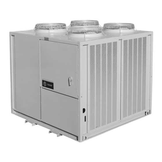
Installation, Operation, and Maintenance
Split System
Cooling Condensers — 20 to 120 Tons
Remote Chillers — 20 to 120 Tons
RAUJ-C20
RAUJ-C25
RAUJ-C30
RAUJ-C40
RAUJ-C50
RAUJ-C60
RAUJ-C80
RAUJ-D10
RAUJ-D12
Only qualified personnel should install and service the equipment. The installation, starting up, and servicing of heating, ventilating, and air-conditioning
equipment can be hazardous and requires specific knowledge and training. Improperly installed, adjusted or altered equipment by an unqualified person
could result in death or serious injury. When working on the equipment, observe all precautions in the literature and on the tags, stickers, and labels that
are attached to the equipment.
April 2020
S S A A F F E E T T Y Y W W A A R R N N I I N N G G
S S S S - - S S V V X X 1 1 1 1 K K - - E E N N
Advertisement
Table of Contents

Related Manuals for Trane RAUJ-C20


Summary of Contents for Trane RAUJ-C20
- Page 1 Installation, Operation, and Maintenance Split System Cooling Condensers — 20 to 120 Tons Remote Chillers — 20 to 120 Tons RAUJ-C20 RAUJ-C25 RAUJ-C30 RAUJ-C40 RAUJ-C50 RAUJ-C60 RAUJ-C80 RAUJ-D10 RAUJ-D12 S S A A F F E E T T Y Y W W A A R R N N I I N N G G Only qualified personnel should install and service the equipment.
- Page 2 A A L L W W A A Y Y S S r r e e f f e e r r t t o o a a p p p p r r o o p p r r i i a a t t e e S S a a f f e e t t y y D D a a t t a a impact to the environment. Trane advocates the...
- Page 3 This document and the information in it are the property of Trane, and may not be used or reproduced F F a a i i l l u u r r e e t t o o f f o o l l l l o o w w i i n n s s t t r r u u c c t t i i o o n n s s b b e e l l o o w w c c o o u u l l d d r r e e s s u u l l t t i i n n in whole or in part without written permission.
-
Page 4: Table Of Contents
Table of Contents Model Number Description ....7 Refrigerant Piping Components ..46 Refrigerant Piping....49 20 to 60 Ton Units . - Page 5 T T a a b b l l e e o o f f C C o o n n t t e e n n t t s s Economizer Cycle ....90 Preliminary Expansion Valve Chilled Water Temperature Adjustment .
- Page 6 T T a a b b l l e e o o f f C C o o n n t t e e n n t t s s Wiring Diagrams ......128 SS-SVX11K-EN...
-
Page 7: Model Number Description
Model Number Description 20 to 60 Ton Units Digit 1 — Unit Type Digit 10 — Design Sequence Digit 18 — Corrosion Protected Condenser Coil R = Condenser Factory Assigned 0 = None J = Corrosion Protected Condenser Coil Digit 2 — Condenser Digit 11 —... -
Page 8: 80 To 120 Ton Units
M M o o d d e e l l N N u u m m b b e e r r D D e e s s c c r r i i p p t t i i o o n n 80 to 120 Ton Units Digit 1 —... -
Page 9: General Information
General Information Unit Inspection • The owner must provide reasonable evidence that the damage did not occur after delivery. To protect against loss due to damage incurred in transit, perform inspection immediately upon receipt of Repair the unit. Notify the appropriate sales representative before Exterior Inspection arranging unit installation or repair. -
Page 10: Manual Motor Protectors
G G e e n n e e r r a a l l I I n n f f o o r r m m a a t t i i o o n n Discharge Line Thermostat the 115V control circuit. If no faults are observed, a green LED will be energized. - Page 11 G G e e n n e e r r a a l l I I n n f f o o r r m m a a t t i i o o n n Figure 2. Component layout and ‘ship-with’ locations – 20 to 60 ton units Condenser Fans Condenser...
-
Page 12: General Data
G G e e n n e e r r a a l l I I n n f f o o r r m m a a t t i i o o n n General Data Table 1. General data — RAUJ condensing units Unit Size (tons) Compressor Data Type... - Page 13 G G e e n n e e r r a a l l I I n n f f o o r r m m a a t t i i o o n n Table 2. Altitude correction multiplier for capacity Altitude (ft.) Configuration 2,000...
-
Page 14: Dimensions And Weights
N N o o t t e e : : EVP chiller is intended for indoor application. If a I I m m p p o o r r t t a a n n t t : : Providing less than the recommended sub-freezing location is required, contact Trane clearances could result in condenser coil... - Page 15 D D i i m m e e n n s s i i o o n n s s a a n n d d W W e e i i g g h h t t s s Table 3.
-
Page 16: Unit Dimensions
D D i i m m e e n n s s i i o o n n s s a a n n d d W W e e i i g g h h t t s s Unit Dimensions Figure 5. - Page 17 D D i i m m e e n n s s i i o o n n s s a a n n d d W W e e i i g g h h t t s s Figure 6.
- Page 18 D D i i m m e e n n s s i i o o n n s s a a n n d d W W e e i i g g h h t t s s Figure 7.
- Page 19 D D i i m m e e n n s s i i o o n n s s a a n n d d W W e e i i g g h h t t s s Figure 8.
- Page 20 D D i i m m e e n n s s i i o o n n s s a a n n d d W W e e i i g g h h t t s s Figure 9.
- Page 21 D D i i m m e e n n s s i i o o n n s s a a n n d d W W e e i i g g h h t t s s Figure 10.
- Page 22 D D i i m m e e n n s s i i o o n n s s a a n n d d W W e e i i g g h h t t s s Figure 11.
- Page 23 D D i i m m e e n n s s i i o o n n s s a a n n d d W W e e i i g g h h t t s s Figure 12.
- Page 24 D D i i m m e e n n s s i i o o n n s s a a n n d d W W e e i i g g h h t t s s Figure 13.
- Page 25 D D i i m m e e n n s s i i o o n n s s a a n n d d W W e e i i g g h h t t s s Figure 14.
- Page 26 D D i i m m e e n n s s i i o o n n s s a a n n d d W W e e i i g g h h t t s s Figure 15.
- Page 27 D D i i m m e e n n s s i i o o n n s s a a n n d d W W e e i i g g h h t t s s Figure 16.
- Page 28 D D i i m m e e n n s s i i o o n n s s a a n n d d W W e e i i g g h h t t s s Figure 17.
- Page 29 D D i i m m e e n n s s i i o o n n s s a a n n d d W W e e i i g g h h t t s s Figure 18.
- Page 30 D D i i m m e e n n s s i i o o n n s s a a n n d d W W e e i i g g h h t t s s Figure 19.
- Page 31 D D i i m m e e n n s s i i o o n n s s a a n n d d W W e e i i g g h h t t s s Figure 20.
- Page 32 D D i i m m e e n n s s i i o o n n s s a a n n d d W W e e i i g g h h t t s s Figure 21.
- Page 33 D D i i m m e e n n s s i i o o n n s s a a n n d d W W e e i i g g h h t t s s Figure 22.
- Page 34 D D i i m m e e n n s s i i o o n n s s a a n n d d W W e e i i g g h h t t s s Figure 23.
- Page 35 D D i i m m e e n n s s i i o o n n s s a a n n d d W W e e i i g g h h t t s s Figure 24.
- Page 36 D D i i m m e e n n s s i i o o n n s s a a n n d d W W e e i i g g h h t t s s Figure 25.
- Page 37 D D i i m m e e n n s s i i o o n n s s a a n n d d W W e e i i g g h h t t s s Figure 26.
- Page 38 D D i i m m e e n n s s i i o o n n s s a a n n d d W W e e i i g g h h t t s s Figure 27.
-
Page 39: Unit Weights
D D i i m m e e n n s s i i o o n n s s a a n n d d W W e e i i g g h h t t s s Unit Weights Table 5. -
Page 40: Installation Mechanical
Installation Mechanical Location Requirements leveling the unit. Isolators are identified by color and/or an isolator part number. Shims under the isolators may Isolation be required if the unit cannot be leveled using the isolator leveling bolt. To minimize unit sound and vibration transmission, one of the following installation methods should be Rigging and Lifting used:... - Page 41 I I n n s s t t a a l l l l a a t t i i o o n n M M e e c c h h a a n n i i c c a a l l Figure 28.
- Page 42 I I n n s s t t a a l l l l a a t t i i o o n n M M e e c c h h a a n n i i c c a a l l Table 6.
-
Page 43: Unit Mounting
I I n n s s t t a a l l l l a a t t i i o o n n M M e e c c h h a a n n i i c c a a l l Unit Mounting Figure 30. -
Page 44: Unit Isolation
I I n n s s t t a a l l l l a a t t i i o o n n M M e e c c h h a a n n i i c c a a l l Unit Isolation Neoprene Isolators (20 to 60 Ton units) Figure 31. -
Page 45: Units)
I I n n s s t t a a l l l l a a t t i i o o n n M M e e c c h h a a n n i i c c a a l l Spring Isolators (20 to 120 Ton units) Figure 32. -
Page 46: Installation
Check the unit for shipping damage and material shortage. If damage or shortage is found, file a For recommended components, see the latest edition freight claim and notify Trane office. of the Applications Guide SS-APG012-EN. • Verify installation location of the unit will provide the required clearance for proper operation. - Page 47 Two ball shutoff valves equal to the OD Tubing size for suction line are required. Interconnecting Liquid Line Tubing. If risers exceed 10 feet, Trane must review the Access Valves (Ports) application The access ports in the suction line allow the operating...
- Page 48 Thermostatic Expansion Valve (TXV) takeoffs to the expansion valve. The sight glass should Trane recommends a balance-ported externally not be used to determine adequate refrigerant charge. equalized valve in order to maintain satisfactory...
-
Page 49: Refrigerant Piping
I I n n s s t t a a l l l l a a t t i i o o n n M M e e c c h h a a n n i i c c a a l l Table 13. Expansion valve selection, 20 to 60 ton MCHE (30% bleed) (continued) Min Tonnage Max Tonnage Selection Manufacturer Trane Part Sporlan ERZE-5-ZGA (BP/30) VAL10491 Sporlan ERZE-6-ZGA (BP/30) - Page 50 I I n n s s t t a a l l l l a a t t i i o o n n M M e e c c h h a a n n i i c c a a l l Refrigerant piping must be properly sized and applied. N N o o t t e e : : If Suction Riser Exceeds 50 Feet, Trane Must These two factors have a very significant effect on both Review The Application.
-
Page 51: Typical Field-Installed Evaporator Piping: Dual-Circuit Examples
I I n n s s t t a a l l l l a a t t i i o o n n M M e e c c h h a a n n i i c c a a l l Typical Field-Installed Evaporator Piping: The unit has a liquid line check valve that prevents liquid refrigerant from flowing backward through the... -
Page 52: Hot Gas Bypass For Commercial Comfort-Cooling Applications
I I n n s s t t a a l l l l a a t t i i o o n n M M e e c c h h a a n n i i c c a a l l Figure 35. -
Page 53: Final Refrigerant Pipe
I I n n s s t t a a l l l l a a t t i i o o n n M M e e c c h h a a n n i i c c a a l l Brazing Procedures Figure 37. -
Page 54: Leak Testing Procedure
The overlap distance should be equal to safety precautions. the diameter of the inner tube. Trane condensing units are shipped with a nitrogen • Wrap the body of each refrigerant line component holding charge. If there is no pressure, the unit must be with a wet cloth to keep it cool during brazing. -
Page 55: Installation Mechanical - Evp
If a subfreezing location is required, 3. Secure the bulb to the suction line with two clamps contact Trane for installation precautions required provided by the manufacturer and insulate the bulb. to prevent damage. 4. Locate liquid line solenoid valve(s) near TXV. -
Page 56: Remote Evp Chiller
D D o o n n o o t t o o p p e e r r a a t t e e w w i i t t h h w w a a t t e e r r l l o o o o p p s s w w i i t t h h l l e e s s s s t t h h a a n n f f i i v v e e a shortened heat exchanger life. Trane encourages... -
Page 57: Chilled Water Piping
I I n n s s t t a a l l l l a a t t i i o o n n M M e e c c h h a a n n i i c c a a l l — — E E V V P P N N o o t t e e : : Water volumes should be calculated as close as Chiller accessory kit includes strainer, water flow possible to maintain constant water flow... - Page 58 I I n n s s t t a a l l l l a a t t i i o o n n M M e e c c h h a a n n i i c c a a l l — — E E V V P P Braze Plate (BPHE) Chiller Strainers should be installed as close as practical to the heat exchanger water inlet (the remote chiller...
- Page 59 I I n n s s t t a a l l l l a a t t i i o o n n M M e e c c h h a a n n i i c c a a l l — — E E V V P P Figure 41.
-
Page 60: Final Water Piping Connections
I I n n s s t t a a l l l l a a t t i i o o n n M M e e c c h h a a n n i i c c a a l l — — E E V V P P Figure 42. -
Page 61: Installation Electrical
Installation Electrical Electrical N N o o t t e e : : Local codes may take precedence. SS-SVX11K-EN... - Page 62 I I n n s s t t a a l l l l a a t t i i o o n n E E l l e e c c t t r r i i c c a a l l SS-SVX11K-EN...
-
Page 63: Wiring Requirements
I I n n s s t t a a l l l l a a t t i i o o n n E E l l e e c c t t r r i i c c a a l l Wiring Requirements W W A A R R N N I I N N G G P P r r o o p p e e r r F F i i e e l l d d W W i i r r i i n n g g a a n n d d G G r r o o u u n n d d i i n n g g... -
Page 64: Low Voltage Wiring (Ac & Dc)
I I n n s s t t a a l l l l a a t t i i o o n n E E l l e e c c t t r r i i c c a a l l •... - Page 65 I I n n s s t t a a l l l l a a t t i i o o n n E E l l e e c c t t r r i i c c a a l l Disconnect Switch External Handle W W A A R R N N I I N N G G (Factory Mounted Option)
-
Page 66: Field Installed Control Wiring
I I n n s s t t a a l l l l a a t t i i o o n n E E l l e e c c t t r r i i c c a a l l Power Wire Sizing and Protection Devices Table 19. - Page 67 I I n n s s t t a a l l l l a a t t i i o o n n E E l l e e c c t t r r i i c c a a l l Supply Fan Interlock W W A A R R N N I I N N G G Control Options Utilizing an Air Handler...
- Page 68 I I n n s s t t a a l l l l a a t t i i o o n n E E l l e e c c t t r r i i c c a a l l N N O O T T I I C C E E chapter for the electrical access locations provided on the unit.
- Page 69 I I n n s s t t a a l l l l a a t t i i o o n n E E l l e e c c t t r r i i c c a a l l panel, refer to the actual unit wiring diagram for power supply for the actuator(s) must be field terminal designation, i.e.
- Page 70 I I n n s s t t a a l l l l a a t t i i o o n n E E l l e e c c t t r r i i c c a a l l Table 25.
- Page 71 I I n n s s t t a a l l l l a a t t i i o o n n E E l l e e c c t t r r i i c c a a l l Figure 46.
- Page 72 I I n n s s t t a a l l l l a a t t i i o o n n E E l l e e c c t t r r i i c c a a l l Figure 47.
- Page 73 I I n n s s t t a a l l l l a a t t i i o o n n E E l l e e c c t t r r i i c c a a l l Figure 48.
- Page 74 I I n n s s t t a a l l l l a a t t i i o o n n E E l l e e c c t t r r i i c c a a l l Figure 49.
- Page 75 I I n n s s t t a a l l l l a a t t i i o o n n E E l l e e c c t t r r i i c c a a l l Figure 50.
- Page 76 I I n n s s t t a a l l l l a a t t i i o o n n E E l l e e c c t t r r i i c c a a l l Figure 51.
- Page 77 I I n n s s t t a a l l l l a a t t i i o o n n E E l l e e c c t t r r i i c c a a l l Discharge Air Sensor (Honeywell 6RT3 or economizer (if applicable) and cycling of compressors...
- Page 78 I I n n s s t t a a l l l l a a t t i i o o n n E E l l e e c c t t r r i i c c a a l l Night Setback installed across Terminals 7 &...
- Page 79 I I n n s s t t a a l l l l a a t t i i o o n n E E l l e e c c t t r r i i c c a a l l Figure 53.
- Page 80 I I n n s s t t a a l l l l a a t t i i o o n n E E l l e e c c t t r r i i c c a a l l •...
- Page 81 I I n n s s t t a a l l l l a a t t i i o o n n E E l l e e c c t t r r i i c c a a l l Figure 55.
-
Page 82: Evp Chiller Control
I I n n s s t t a a l l l l a a t t i i o o n n E E l l e e c c t t r r i i c c a a l l W W A A R R N N I I N N G G •... - Page 83 I I n n s s t t a a l l l l a a t t i i o o n n E E l l e e c c t t r r i i c c a a l l Figure 57. Field connection diagram - RAUJ-C20-60 - EVP chiller applications 2307-9122 N N o o t t e e : : See wiring notes on previous figure “Field...
- Page 84 I I n n s s t t a a l l l l a a t t i i o o n n E E l l e e c c t t r r i i c c a a l l Figure 58.
- Page 85 I I n n s s t t a a l l l l a a t t i i o o n n E E l l e e c c t t r r i i c c a a l l W W A A R R N N I I N N G G A ground wire must be installed between the EVP remote panel and the unit control panel.
-
Page 86: Operating Principles
Operating Principles Component Locations Condenser Fans Figure 59. Condenser fan locations: 20 to 60 ton units 20 Ton 25 & 30 Ton Low Ambient Low Ambient Control Panel Control Panel Damper Damper 50 & 60 Ton 40 Ton Low Ambient Low Ambient Control Panel Control Panel... -
Page 87: Compressors
O O p p e e r r a a t t i i n n g g P P r r i i n n c c i i p p l l e e s s Compressors Figure 61. Compressor locations: 20 to 60 ton units 20 Ton Condensing Unit 25 &... -
Page 88: Compressor Junction Box
O O p p e e r r a a t t i i n n g g P P r r i i n n c c i i p p l l e e s s Compressor Junction Box Figure 63. -
Page 89: Unit Operation
O O p p e e r r a a t t i i n n g g P P r r i i n n c c i i p p l l e e s s Figure 64. Junction box: 80-120 Ton units Crankcase Heater HPC Wires Wires... -
Page 90: Economizer Cycle
O O p p e e r r a a t t i i n n g g P P r r i i n n c c i i p p l l e e s s Economizer Cycle When the economizer cannot handle the cooling requirement or when the outdoor ambient conditions The economizer is only allowed to function if the... -
Page 91: Thermostatic Expansion Valve
O O p p e e r r a a t t i i n n g g P P r r i i n n c c i i p p l l e e s s minimum “Off” time has been satisfied (Point A). The maintain its current position, i.e., no staging of cooling minimum “fast response”... -
Page 92: Low Ambient Dampers
O O p p e e r r a a t t i i n n g g P P r r i i n n c c i i p p l l e e s s Table 27. RAUJ condenser fan sequencing data: 20 to 60 ton units Controlling Device Fan "ON"... -
Page 93: Low Ambient Thermostats
O O p p e e r r a a t t i i n n g g P P r r i i n n c c i i p p l l e e s s prevent low oil viscosity and foaming during when the ambient temperature reaches 30ºF and closes compressor starts. -
Page 94: Pre-Start
Pre-Start Use the checklist provided below in conjunction with • Check the compressor oil levels. Oil levels must be the “General Unit Requirement” checklist” to ensure near or above the top of all compressor sight that the unit is properly installed and ready for glasses. -
Page 95: Standing Vacuum Test
P P r r e e - - S S t t a a r r t t The oil in the vacuum pump should be changed each N N o o t t e e : : It is unlawful to release refrigerant into the time the pump is used with a high quality vacuum atmosphere. -
Page 96: Discharge Air Controller Checkout
W7100A accessory tool kit (Trane part # TOL-0101 or Honeywell part # 4074EDJ). N N o o t t e e : : It is not necessary to set the “Reset F” dial since the factory installed jumper across 1. - Page 97 P P r r e e - - S S t t a a r r t t W W A A R R N N I I N N G G switch to the “OFF” position. 21. Remove the wires from terminals R, B, W, & Y. L L i i v v e e E E l l e e c c t t r r i i c c a a l l C C o o m m p p o o n n e e n n t t s s ! ! 22.
-
Page 98: Discharge Air Sensor Checkout
P P r r e e - - S S t t a a r r t t Discharge Air Sensor Checkout Figure 69. W7100A discharge air controller (Honeywell Sensor) COOL W W A A R R N N I I N N G G 24 VAC H H a a z z a a r r d d o o u u s s V V o o l l t t a a g g e e ! ! COOL... -
Page 99: Evp Chiller Control Checkout
. . checked out using a highly accurate digital voltmeter, the W7100 accessory tool kit (Trane part # TOL-0101 or 1. Turn all control switches to the “Off” position to... -
Page 100: W7100G)
P P r r e e - - S S t t a a r r t t W W A A R R N N I I N N G G Figure 71. W7100G chilled water controller L L i i v v e e E E l l e e c c t t r r i i c c a a l l C C o o m m p p o o n n e e n n t t s s ! ! COOL F F a a i i l l u u r r e e t t o o f f o o l l l l o o w w a a l l l l e e l l e e c c t t r r i i c c a a l l s s a a f f e e t t y y p p r r e e c c a a u u t t i i o o n n s s 24 VAC... -
Page 101: Master Energy Control Checkout
P P r r e e - - S S t t a a r r t t N N o o t t e e : : Before condemning the sensor, verify that N N o o t t e e : : The wires that are still connected to one side the connecting cable resistance is not of the “Cool Relay”... -
Page 102: Zone Thermostat Checkout
P P r r e e - - S S t t a a r r t t Zone Thermostat Checkout thermostat “voltage output” ramps. (Honeywell T7067) 4. To check the “Cooling” output signal, place the voltmeter leads between thermostat Terminals 1 & A A v v a a i i l l a a b b l l e e O O n n l l y y F F o o r r 2 2 0 0 - - 6 6 0 0 T T o o n n U U n n i i t t s s 4. - Page 103 P P r r e e - - S S t t a a r r t t 1. Turn the control circuit switch 1S2, in the unit 6RT1 is out of range; replace it. control panel, to the “OFF” position. N N o o t t e e : : Before condemning the sensor, verify that 2.
-
Page 104: Voltage Imbalance
P P r r e e - - S S t t a a r r t t Electrical Phasing Figure 73. W973 master energy controller (MEC) W W A A R R N N I I N N G G HEAT H H a a z z a a r r d d o o u u s s V V o o l l t t a a g g e e ! ! F F a a i i l l u u r r e e t t o o d d i i s s c c o o n n n n e e c c t t p p o o w w e e r r b b e e f f o o r r e e s s e e r r v v i i c c i i n n g g c c o o u u l l d d... -
Page 105: Start-Up
Start-Up Low Ambient Damper To check damper operation, jumper between the sensor input terminals 6 and 7 and/or 11 and 12 (if Adjustment applicable). Controller output signal will go to 10 VDC (Factory or Field Installed) and damper will drive to full open position. When a unit is ordered with the low ambient option EVP Chiller Applications (model number digit 11 =1), a damper is factory... -
Page 106: System Airflow Measurement
S S t t a a r r t t - - U U p p Measuring Airflow W W A A R R N N I I N N G G L L i i v v e e E E l l e e c c t t r r i i c c a a l l C C o o m m p p o o n n e e n n t t s s ! ! With the supply fan rotating in the proper direction, measure the amperage at the supply fan contactor. -
Page 107: Preliminary Expansion Valve
S S t t a a r r t t - - U U p p Preliminary Expansion Valve leaving the evaporator at nominal design conditions. Thermal expansion valves with bleeds are set to their Adjustment highest superheat setting. Actual superheat depends on many factors (valve vs. -
Page 108: Adding Preliminary Charge
S S t t a a r r t t - - U U p p Table 32. Thermal expansion valve manufacturer settings - no bleed — Danfoss Standard off the shelf nominal valve settings Field adjust Field adjust Superheat for 18°F (DX for 15°F CW turns... -
Page 109: Compressor Start-Up(All Systems)
S S t t a a r r t t - - U U p p N N O O T T I I C C E E I I m m p p o o r r t t a a n n t t : : Do not attempt to charge the system with the low ambient dampers and/or hot gas C C o o m m p p r r e e s s s s o o r r D D a a m m a a g g e e ! ! bypass operating (if applicable). - Page 110 S S t t a a r r t t - - U U p p outdoor temperatures. If the outdoor temperature is could be improperly phased. A main unit power less than 80°F, temporarily disable the fan pressure phase protection module (1U3) is located in the control switches (4S11, 4S12) or (4S7, 4S8) on 80 - RAUJ control box and interrupts control circuit 120 Ton units.
- Page 111 S S t t a a r r t t - - U U p p g. Subtract the total charge already added from at this time. Follow the procedures discussed the table in Preliminary Charging section charge earlier to confirm proper rotation of these estimate for condensing unit at the appropriate condenser fans.
-
Page 112: Motors Rotating Backward
S S t t a a r r t t - - U U p p Figure 74. System charging chart (all units) 150" lines 50’ lines 150’ lines Remove Charge Add Charge Add Charge Add Charge Add Charge Liquid Line Temp at Outdoor Unit, °F Motors Rotating Backward W W A A R R N N I I N N G G H H a a z z a a r r d d o o u u s s V V o o l l t t a a g g e e ! ! -
Page 113: Subcooling
"Off" position. Lock the N N o o t t e e : : On many Trane fan/coil units, an access valve disconnect switch in the open position while is provided close to the expansion valve bulb working at the unit. -
Page 114: Compressor Sequencing
S S t t a a r r t t - - U U p p Table 36. Pressure control switch settings (psi) Table 37. Compressor sequence: 20-120 Ton units (continued) Pressure Switch Make Break Control Unit % Loaded Hi Pressure Step Size Circuit 1... - Page 115 S S t t a a r r t t - - U U p p Figure 76. 25 Ton cooling cycle pressure curve Figure 79. 50 Ton cooling cycle pressure curve 25T Cooling Cycle Pressure Curve 50T Cooling Cycle Pressure Curve All compressors and condenser fans running All compressors and condenser fans running 105°F OD...
-
Page 116: Final System Setup
S S t t a a r r t t - - U U p p Final System Setup Figure 82. 100 Ton cooling cycle pressure curve W W A A R R N N I I N N G G 100T Cooling Cycle Pressure Curve All compressors and condenser fans running H H a a z z a a r r d d o o u u s s V V o o l l t t a a g g e e ! ! - Page 117 S S t t a a r r t t - - U U p p SS-SVX11K-EN...
- Page 118 S S t t a a r r t t - - U U p p SS-SVX11K-EN...
-
Page 119: Maintenance
Maintenance Monthly Maintenance I I m m p p o o r r t t a a n n t t : : Use a hand grease gun to lubricate bearings. Add grease until a light bead Air Handling Equipment appears all around the seal. -
Page 120: Coil Cleaning
Water Strainer Maintenance Trane Parts Center. N N o o t t e e : : DO NOT use any detergents with To protect the evaporator and for maximum efficiency, microchannel coils. -
Page 121: Evp Evaporator Replacement
The following discussion describes some of the operational sounds of Trane R-410A scroll F F a a i i l l u u r r e e t t o o f f o o l l l l o o w w i i n n s s t t r r u u c c t t i i o o n n s s b b e e l l o o w w c c o o u u l l d d r r e e s s u u l l t t i i n n compressors. -
Page 122: Compressor Replacement
M M a a i i n n t t e e n n a a n n c c e e N N O O T T I I C C E E a dedicated device for removing oil. It is good practice to flush the suction device with clean oil prior to use. -
Page 123: 20 Ton
M M a a i i n n t t e e n n a a n n c c e e Precision Suction Restrictor Charge the new oil into the Schrader valve or oil drain valve on the shell of the compressor. Due to the RAUJ tandems with unequal compressors and all moisture absorption properties of POE oil, do not use RAUJ trios use precision suction restrictors to balance... - Page 124 M M a a i i n n t t e e n n a a n n c c e e Table 43. Compressor circuit breakers (200-230 volts) (continued) Must Trip Must Hold Voltage 1A / 2A 1B / 2B 1C / 2C 1A / 2A 1B / 2B...
-
Page 125: Suction Line Filter
M M a a i i n n t t e e n n a a n n c c e e Suction Line Filter Figure 88. Suction line filter installation: 80 to120 Ton units Figure 87. Suction line filter installation: 20 to 60 Ton units 25”... -
Page 126: Fall Restraint - Condenser Roof
M M a a i i n n t t e e n n a a n n c c e e Fall Restraint — Condenser Roof Figure 89. Fall restraint slot W W A A R R N N I I N N G G F F a a l l l l i i n n g g O O f f f f E E q q u u i i p p m m e e n n t t ! ! F F a a i i l l u u r r e e t t o o f f o o l l l l o o w w i i n n s s t t r r u u c c t t i i o o n n s s b b e e l l o o w w c c o o u u l l d d r r e e s s u u l l t t i i n n d d e e a a t t h h o o r r s s e e r r i i o o u u s s i i n n j j u u r r y y . -
Page 127: Warranty And Liability Clause
This warranty* is extended by Trane Inc. and applies including implied warranties of merchantability and only to commercial equipment rated 20 Tons and fitness for particular use. - Page 128 Wiring Diagrams N N o o t t e e : : Published unit wiring diagrams (individual, separate diagrams for unitary product lines) are available via e-Library. Drawing Description Number Unit Connection Wiring Split - System Condensing Unit Air Cooled RAUJ 20-60 Ton units 2307-4483 Connection-Adder Plates Split System Condensing Unit RAUJ 80-120 Ton units 2307-4495...
- Page 129 N N o o t t e e s s SS-SVX11K-EN...
- Page 130 N N o o t t e e s s SS-SVX11K-EN...
- Page 131 N N o o t t e e s s SS-SVX11K-EN...
- Page 132 For more information, please visit trane.com or tranetechnologies.com. Trane has a policy of continuous product and product data improvements and reserves the right to change design and specifications without notice. We are committed to using environmentally conscious print practices.