
Related Manuals for Trane RAUC-C20


Summary of Contents for Trane RAUC-C20
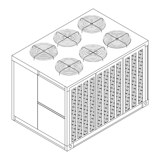
- Page 1 Installation Operation Maintenance Remote Split System Units Air Cooled Condensing Units and EVP Chillers Models “V” and Later Design Sequence RAUC-C20 RAUC-C40 RAUC-C25 RAUC-C50 RAUC-C30 RAUC-C60 SS-SVX09A-EN June 2008...
- Page 2 CFCs such as HCFCs and HFCs. Responsible Refrigerant Practices! Trane believes that responsible refrigerant practices are important to the environment, our customers, and the air conditioning industry. All technicians who handle refrigerants must be certified. The Federal Clean Air Act (Section 608) sets forth the requirements for handling, reclaiming, recovering and recycling of certain refrigerants and the equipment that is used in these service procedures.
-
Page 3: Table Of Contents
Table of Contents General Information ........... . 5 Model Number Description . - Page 4 Outside Air Thermostat (5S57 Field Provided) ..... 61 Constant Volume Control (Honeywell 973) ......63 System Pre-Start Procedures .
-
Page 5: General Information
General Information Model Number Description All Trane products are identified by a multiple-character model number that precisely identifies a particular type of unit. An explanation of the alphanumeric identification code is provided below. Its use will enable the owner/operator, installing contractors, and service engineers to define the operation, specific components, and other options for any specific unit. - Page 6 General Information Evaporator Nameplate (EVP Chiller Applications Only) The nameplate is located on the same side of the refrigerant connections near the top. To view the nameplate, remove the tape over the area and spread the insulation. Retape the insulation after viewing.
-
Page 7: Installation
Take photos of the damage, if possible. The owner must provide reasonable evidence that the damage did not occur after delivery. [ ] Notify the appropriate Trane office before installing or repairing a damaged unit. Unit Clearances... -
Page 8: Unit Dimensions & Weight Information
Installation NOTICE To prevent internal chiller damage due to freezing, do not install the BPHE chiller outdoors without adequate freeze protection. Allow adequate clearance for water and refrigerant piping connections, space to perform service procedures, i.e. read gauges, thermometers, and operate water system valves. Unit Dimensions &... - Page 9 Installation Figure 2. Typical Installation Clearances for Single, Multiple or Pit Applications SS-SVX09A-EN...
- Page 10 Installation Figure 3. RAUC-C20 Unit Dimensional Data & Recommended Clearances SS-SVX09A-EN...
- Page 11 Installation Figure 4. RAUC-C25 Unit Dimensional Data & Recommended Clearances SS-SVX09A-EN...
- Page 12 Installation Figure 5. RAUC-C30 Unit Dimensional Data & Recommended Clearances SS-SVX09A-EN...
- Page 13 Installation Figure 6. RAUC-C40 Unit Dimensional Data & Recommended Clearances SS-SVX09A-EN...
- Page 14 Installation Figure 7. RAUC-C50 Unit Dimensional Data & Recommended Clearances SS-SVX09A-EN...
- Page 15 Installation Figure 8. RAUC-C60 Unit Dimensional Data & Recommended Clearances SS-SVX09A-EN...
- Page 16 Installation Figure 9. BPHE 20 Evaporator Chiller Dimensions Note: All water connections are Victaulic. SS-SVX09A-EN...
- Page 17 Installation Figure 10. BPHE 25 Evaporator Chiller Dimensions Note: All water connections are Victaulic. SS-SVX09A-EN...
- Page 18 Installation Figure 11. BPHE 30 Evaporator Chiller Dimensions Note: All water connections are Victaulic. SS-SVX09A-EN...
- Page 19 Installation Figure 12. BPHE 40 Evaporator Chiller Dimensions Note: All water connections are Victaulic. SS-SVX09A-EN...
- Page 20 Installation Figure 13. BPHE 50 Evaporator Chiller Dimensions Note: All water connections are Victaulic. SS-SVX09A-EN...
- Page 21 Installation Figure 14. BPHE 60 Evaporator Chiller Dimensions Note: All water connections are Victaulic. SS-SVX09A-EN...
- Page 22 Installation Table 1. Typical Unit Weights & Point Loading Data Unit Weight on Isolator @ Mounting Location Operating Weight Location 1 Unit Size 1522 1720 1640 1842 1824 2115 2769 3102 3148 3540 3480 4050 Note: Mounting locations correlate with those shown in point loading illustration Table 2.
-
Page 23: Rigging
Installation Rigging WARNING Heavy Objects! Do not use cables (chains or slings) except as shown. Each of the cables (chains or slings) used to lift the unit must be capable of supporting the entire weight of the unit. Lifting cables (chains or slings) may not be of the same length. -
Page 24: Unit Isolation
Installation Unit Isolation To minimize unit sound and vibration transmission, one of the following installation methods should be used: 1. Install the unit directly on an isolated (detached) concrete pad or on isolated concrete footings located at each unit load point. 2. -
Page 25: Leveling The Unit
Installation Spring Isolators Install the spring isolators at each unit mounting (load) point using the following procedure: 1. Elevate the unit (one side at a time) to allow access to the base rail mounting holes. WARNING Heavy Objects! Use solid type blocks, i.e. 4" X 4" wood blocks or similar material to prevent collapsing. Keep hands and other body limbs clear of elevated base rail while installing isolators. -
Page 26: Shipping Fasteners
Installation Table 4. Typical Spring Isolator Selection & Location Spring Isolator Part Number @ Mounting Location Location 1 Location 2 Location 3 Location 4 Location 5 Location 6 Unit Tons CP-1-27 CP-1-28 CP-1-26 CP-1-27 CP-1-26 CP-1-26 CP-1-25 CP-1-26 CP-1-28 CP-1-28 CP-1-27 CP-1-27 CP-1-26... -
Page 27: General Unit Requirements
[ ] Verify that the power supply complies with the unit nameplate specifications. [ ] Check the unit for shipping damage and material shortage; file a freight claim and notify Trane office. [ ] Verify that the installation location of the unit will provide the required clearance for proper operation. -
Page 28: Evp Chilled Water Piping Requirements
Installation WARNING Hazard of Explosion! Never use an open flame to detect gas leaks. Explosive conditions may occur. Use a leak test solution or other approved methods for leak testing. Failure to follow recommended safe leak test procedures could result in death or serious injury or equipment or property-only-damage. [ ] Leak test the system. -
Page 29: Field Installed Control Wiring Requirements
Installation WARNING Ground Wire! All field-installed wiring must be completed by qualified personnel. All field-installed wiring must comply with NEC and applicable local codes. Failure to follow this instruction could result in death or serious injuries. WARNING Grounding Required! Follow proper local and state electrical code on requirements for grounding. Failure to follow code could result in death or serious injury. - Page 30 Installation WARNING Ground Wire! All field-installed wiring must be completed by qualified personnel. All field-installed wiring must comply with NEC and applicable local codes. Failure to follow this instruction could result in death or serious injuries. WARNING Grounding Required! Follow proper local and state electrical code on requirements for grounding. Failure to follow code could result in death or serious injury.
-
Page 31: Low Voltage Wiring (Ac & Dc)
Installation Low Voltage Wiring (AC & DC) WARNING Hazardous Voltage! Disconnect all electric power, including remote disconnects before servicing. Follow proper lockout/tagout procedures to ensure the power can not be inadvertently energized. Failure to disconnect power before servicing could result in death or serious injury. Variable Air Volume (VAV) Units [ ] Install a field provided remote system control switch to activate the system. - Page 32 Thermostatic Expansion Valve (TEV) Trane recommends a balance-ported externally equalized valve in order to maintain satisfactory superheat control down to lower valve loading conditions and to compensate for pressure drops between the expansion valve and superheat control point (evaporator refrigerant outlet).
- Page 33 Split System Component Number Definitions (1)Interconnecting Suction Line Tubing (2)Suction Line Filter (3)Shutoff Valves - Manual ball valves (4)Interconnecting Liquid Line Tubing. If risers exceed 10 feet, Trane must review the application (5)Shutoff valves - Manual ball valves (6)Access Ports (7)Liquid Line Filter Drier...
-
Page 34: Refrigerant Piping
5. Slope suction lines toward the evaporator ¼-inch to 1-inch for every 10 feet. 6. Insulate the suction lines. 7. The suction line filter should be as close to the compressor as possible. Note: If Suction Riser Exceeds 50 Feet, Trane Must Review The Application. Suction Line Interconnecting Tubing OD Vertical... -
Page 35: Liquid Line Piping
Installation Liquid Line Piping Liquid line sizes are based on their ability to provide a minimum of 5 degrees F (2.7ºC) of sub- cooling at the expansion valve throughout the unit’s operating system. Increasing the liquid line size does not increase the available sub-cooling. The uniform liquid line size, pre-selected in the Table below, are independent of the line length or rise within the permissible guidelines to maintain this minimum required 5 degree F (2.7ºC) sub-cooling at the expansion valve for a properly charged RAUC unit operating in a normal air conditioning application. -
Page 36: Evaporator Piping
Installation Evaporator Piping 1. Install the TXV directly to the unit liquid connection. 2. Locate the TXV bulb midway between the 90 degrees bends on top of the suction line as illustrated in Figure 19 Figure 3. Secure the bulb to the suction line with two clamps provided by the manufacturer and insulate the bulb. -
Page 37: Hot Gas Bypass For Commercial Comfort-Cooling Applications
Installation Hot Gas Bypass for Commercial Comfort-Cooling Applications Hot gas bypass is not recommended for use on RAUC units. Frostat™ is the preferred method of protecting the evaporator from freeze-up. It turns off compressors when the coil frosting is sensed. The compressor is allowed to operate when the coil temperature rises a few degrees above the frosting condition. -
Page 38: Brazing Procedures
Installation Brazing Procedures WARNING Hazard of Explosion and Deadly Gases! Never solder, braze or weld on refrigerant lines or any unit components that are above atmospheric pressure or where refrigerant may be present. Always remove refrigerant by following the guidelines established by the EPA Federal Clean Air Act or other state or local codes as appropriate. -
Page 39: Leak Testing Procedure
Failure to do so could result in death or serious injury. Trane condensing units are shipped with a Nitrogen holding charge. If there is no pressure, the unit must be leak tested to determine the location of leak as follows: Note: These service procedures require working with refrigerant, Do NOT release refrigerant to the atmosphere! The service technician must comply with all federal, state, and local laws. -
Page 40: Chilled Water Piping
Installation 7. If a leak is located, use proper procedures to remove the refrigerant/nitrogen mixture, break the connection and remake as a new joint. Retest for leaks after making repairs. 8. Open the liquid line service valve and the compressor discharge service valve. Chilled Water Piping Evaporator water inlet and outlet types, sizes and locations are shown in Figure 9... - Page 41 Installation Figure 21. Evaporator Water-Pressure Drop Note: Factor to convert “Feet of Water” to “Lbs. per Sq. Inch” (PSI): 2.3 Feet of Water = 1 PSI SS-SVX09A-EN...
- Page 42 Installation Air Vents Vents must be installed at high points in the piping system to facilitate air purging during the filling process. Water Pressure Gauges Install pressure gauge(s) to monitor the entering and leaving chilled water pressure. NOTICE To prevent evaporator damage, do not exceed 150 psig evaporator pressure. Water Shutoff Valves Provide shutoff valves in the “Supply”...
- Page 43 Installation NOTICE Failure to use thermal paste could result in erratic temperature sensing resulting in equipment damage. Freezestat A Bulb-well (located inside the remote panel) must be installed in the leaving water piping as close to the chiller barrel as possible. It should be located upstream of the Temperature Sensor location. The Freezestat, located within the remote panel, is equipped with a remote Sensing Bulb and 20 feet of capillary tube.
-
Page 44: Final Water Piping Connections
Installation Figure 23. Optional Flow Switch Illustration Figure 24. Freezestat Bulb-well, Temperature Sensor & Well NOTICE Failure to use thermal paste could result in erratic temperature sensing resulting in equipment damage. Final Water Piping Connections 1. All water piping to the system should be flushed thoroughly before making the final connections. NOTICE If an acidic commercial flushing solution is used, construct a temporary bypass around the EVP chiller to prevent damage to the internal components of the evaporator. -
Page 45: Field Installed Power Wiring
Installation 3. Install the drain plug, (if no drain is used) or ensure the drain shutoff valve is closed. 4. While filling the chiller system with solution, vent the air from the system at the highest points. NOTICE To prevent possible damage to the equipment, do not use untreated or improperly treated water in the system. -
Page 46: Main Unit Power Wiring
Installation Main Unit Power Wiring WARNING Hazardous Voltage! Disconnect all electric power, including remote disconnects before servicing. Follow proper lockout/tagout procedures to ensure the power can not be inadvertently energized. Failure to disconnect power before servicing could result in death or serious injury. Table 7 lists the field connection wire ranges for both the main power terminal block 1TB1 and the optional main power disconnect switch 1S1. -
Page 47: Power Wire Sizing And Protection Device
Installation Power Wire Sizing and Protection Device Equations Table 7. Customer Connection Wire Range To correctly size the main power wiring for the unit, use the appropriate calculation(s) listed below. Read the load definitions that follow and use Calculation #1 for determining the MCA (Minimum Circuit Ampacity), MOP (Maximum Over current Protection), and RDE (Recommended Dual Element fuse size) for each unit. - Page 48 Installation Calculation #2 Disconnect Switch Sizing (DSS) DSS = 1.15 X (LOAD 1 + LOAD 2 + LOAD 4) Table 8. Electrical Service Sizing Data Unit Characteristics Condenser Fan Motor Compressor Motor Max. Rec. Allow- Over- Dual able Min. current Element (Ea) (Ea)
-
Page 49: Field Installed Control Wiring
Installation Table 8. Electrical Service Sizing Data (continued) Unit Characteristics Condenser Fan Motor Compressor Motor Max. Rec. Allow- Over- Dual able Min. current Element (Ea) (Ea) (Ea) (Ea) (Ea) (Ea) Electrical Voltage Circuit Protect Fuse Model Charac. Range -ion Size (Ea) No HP (Ea) (Ea) - Page 50 Installation liquid line solenoid valve(s). Supply Fan Interlock (Control options utilizing an Air Handler) The normally open evaporator fan interlock auxiliary contacts and the evaporator fan controls; system On/Off switch, fan starter/contactor, and overloads, must be wired as illustrated in the appropriate interlock connection wiring diagram for the specified application.
-
Page 51: Controls Using 24 Vac
Installation Controls using 24 VAC WARNING Hazardous Voltage! Disconnect all electric power, including remote disconnects before servicing. Follow proper lockout/tagout procedures to ensure the power can not be inadvertently energized. Failure to disconnect power before servicing could result in death or serious injury. Before installing any connecting wiring, refer to Figure 3 Figure 8... -
Page 52: Economizer Actuator Circuit
Installation These components may include: Field installed Discharge Duct Sensor (6RT1 CV units); Field installed Return Duct Sensor (6RT6 CV units); Field installed Discharge Air Sensor (6RT3 VAV units); Field installed Chilled Water Sensor (6RT2 EVP units); 1. Wiring for the components utilizing a DC analog input\output signal must be shielded cable (Belden 8760 or equivalent). -
Page 53: No System Control
Installation Economizer Actuator Circuit Legend Device Designation Device Designation Parts And Notes M.H. M955, (Up to 3 motors may be Modutral Motor controlled as shown. Additional motors must be slaved.) Transformer M.H. 13081B; cover mounted Enthalpy Control M.H. H2051046 Minimum Position Potentiometer M.H. - Page 54 Installation Figure 25. Field Connection Diagram or RAUC-C20 - C60 “No System Controls” Applications Refer to Wiring Notes on p. 55 SS-SVX09A-EN...
-
Page 55: Field Connection Diagram Notes For All System Control Options
Installation Field Connection Diagram Notes for all System Control Options SS-SVX09A-EN... -
Page 56: Variable Air Volume Control (Honeywell W7100A)
Installation Variable Air Volume Control (Honeywell W7100A) In a variable air volume system, the desired space temperature is maintained by varying the amount of conditioned air being delivered to the space. As the cooling requirements of the space decreases, less air is delivered to the zone; conversely, as the cooling requirements of the space increases, a greater volume of air is delivered to the zone. -
Page 57: Suction Line Thermostat
Installation Suction Line Thermostat Each unit ordered with variable air volume controls (digit 9 in the model number) is shipped with a suction line thermostat (6S63) that must be field installed. Locate the thermostat close to the expansion valve bulb on a slightly flattened portion of the suction line. -
Page 58: Evp Chiller Control
Installation Figure 27. Field Connection Diagram for RAUC-C20 - 60 “Variable Air Volume” Application Refer to Wiring Notes on Page p. 55 EVP Chiller Control Each unit ordered for EVP Chiller applications (digit 9 in the model number), is shipped with the... - Page 59 Installation connection diagram illustrated in Figure 29 for the interconnecting points between the remote panel and the unit’s control panel. WARNING Ground Wire! All field-installed wiring must be completed by qualified personnel. All field-installed wiring must comply with NEC and applicable local codes. Failure to follow this instruction could result in death or serious injuries.
-
Page 60: Chilled Water Temperature Sensor (Honeywell 6Rt2)
Installation Figure 28. EVP Chiller Remote Panel Chilled Water Temperature Sensor (Honeywell 6RT2) With the sensor installed in its proper location within the chilled water piping (Figure 18), connect shielded cable (Belden 8760 or equivalent) from the sensor leads to the leads inside the remote panel. -
Page 61: Outside Air Thermostat (5S57 Field Provided)
Installation Outside Air Thermostat (5S57 Field Provided) The setpoint for the outside air thermostat is based upon the working ambient selected when the unit was ordered. A Zero (“0”) in the 11th digit of the model number indicates the system is designed for standard ambient operation of 40ºF and above. - Page 62 Installation Figure 29. Field Connection Diagram for RAUC-C20 - 60 “EVP Chiller” Applications Refer to Wiring Notes on Page p. 55 SS-SVX09A-EN...
-
Page 63: Constant Volume Control (Honeywell 973)
Installation Constant Volume Control (Honeywell 973) The descriptions of the following basic input devices used with the Honeywell 973 Master Energy Controller (MEC) are to acquaint the operator with their function as they interface with the controller. Refer to the field connection diagram in Figure 32 for the specific component connections at the unit’s control panel. - Page 64 Installation Figure 30. T7067 Electronic Zone Thermostat & Q667 Switching Subbase Figure 31. Q667 Switching Subbase & T7067 Thermostat Terminal Identification SS-SVX09A-EN...
- Page 65 Installation Table 11. (Q667) Switching Subbase Subbase Switch Positions Check Continuity between These Circuit should System Terminal Pairs 9 (Subbase) & 10 (Subbase) Closed 9 (Subbase) & 10 (Subbase) Open AUTO 5 (Subbase) & 5 (T’stat) Open 4 (Subbase) & 4(T’Stat) Open 9 (Subbase) &...
- Page 66 Installation Figure 32. Field Connection Diagram for RAUC- C20 through 60 “Constant volume” Applications Refer to Wiring Notes on Page p. 55 SS-SVX09A-EN...
- Page 67 Installation Figure 33. 6RT1 Discharge Air Sensor Assembly SS-SVX09A-EN...
-
Page 68: System Pre-Start Procedures
System Pre-Start Procedures Use the checklist provided below in conjunction with the “General Unit Requirement” checklist” to ensure that the unit is properly installed and ready for operation. Be sure to complete all of the procedures described in this section before starting the unit for the first time. WARNING Hazardous Voltage! Disconnect all electric power, including remote disconnects before servicing. -
Page 69: System Evacuation Procedures
System Pre-Start Procedures before filling with water to displace any air in the barrel. Close vent ports or replace the vent plug after purging or filling. [ ] Once the system has been filled, inspect the entire chilled water piping system for leaks. Make any necessary repairs before proceeding. - Page 70 System Pre-Start Procedures Note: It is unlawful to release refrigerant into the atmosphere. When service procedures require working with refrigerants, the service technician must comply with all Federal, State, and local laws. Refer to the General Service Bulletin MSCU-SB-1 (latest edition). Standing Vacuum Test Once 300 microns or less is obtained, close Valve A and leave valves B and C open.
-
Page 71: Discharge Air Controller Checkout (Honeywell W7100A)
The W7100A (7U11) discharge air controller can be checked out using a highly accurate digital volt- ohmmeter and the W7100A accessory tool kit (Trane part # TOL-0101 or Honeywell part # 4074EDJ). 1. Turn all control switches to the “OFF” position to deactivate the Evaporator Fan and the Mechanical Cooling. - Page 72 System Pre-Start Procedures 5. Install a jumper across the P and P1 terminals (remote setpoint input), and another jumper across terminals 6 and 7 (reset input) if reset is enabled. 6. Disconnect the wires from terminals T and T1 (discharge air sensor). 7.
- Page 73 System Pre-Start Procedures In approximately 5 minutes; measure the voltage across terminals R (-) & W (+). The measured voltage should drop to approximately 0.2 VDC. 20. Turn the control circuit switch 1S2, in the unit control panel, and the main power disconnect switch to the “OFF”...
-
Page 74: Discharge Air Sensor Checkout (Honeywell Sensor)
System Pre-Start Procedures Discharge Air Sensor Checkout (Honeywell Sensor) WARNING Hazardous Voltage! Disconnect all electric power, including remote disconnects before servicing. Follow proper lockout/tagout procedures to ensure the power can not be inadvertently energized. Failure to disconnect power before servicing could result in death or serious injury. 1. -
Page 75: Evp Chiller Control Checkout (Honeywell W7100G)
The W7100G (6U11) chilled water controller can be checked out using a highly accurate digital volt- ohmmeter, the W7100 accessory tool kit (Trane part # TOL-0101 or Honeywell part # 4074EDJ), and the Honeywell 4074EFV resistor bag assembly. - Page 76 System Pre-Start Procedures 10. “Close” the main power disconnect switch and turn the control circuit switch 1S2, in the unit control panel, “ON” . WARNING High Voltage is Present at Terminal Block 1TB1 or Unit Disconnect Switch 1S1. To prevent injury or death form electrocution, it is the responsibility of the technician to recognize this hazard and use extreme care when performing service procedures with the electrical power energized.
-
Page 77: Chilled Water Sensor Checkout (Honeywell Sensor)
System Pre-Start Procedures Figure 38. W7100G Chilled Water Controller Chilled Water Sensor Checkout (Honeywell Sensor) WARNING Hazardous Voltage! Disconnect all electric power, including remote disconnects before servicing. Follow proper lockout/tagout procedures to ensure the power can not be inadvertently energized. Failure to disconnect power before servicing could result in death or serious injury. -
Page 78: Master Energy Control Checkout
System Pre-Start Procedures Master Energy Control Checkout WARNING Hazardous Voltage! Disconnect all electric power, including remote disconnects before servicing. Follow proper lockout/tagout procedures to ensure the power can not be inadvertently energized. Failure to disconnect power before servicing could result in death or serious injury. 1. -
Page 79: Zone Thermostat Checkout (Honeywell T7067)
System Pre-Start Procedures 10. Measure the voltage again across Terminals R (-) and W (+). The measured voltage should now be approximately 0.2 VDC. 11. Turn the control circuit switch 1S2, in the unit control panel, to the “OFF” position. 12. -
Page 80: Discharge Air Sensor Checkout (Honeywell 6Rt1)
System Pre-Start Procedures Table 12. Zone Thermostat (6U37) “Voltage Output” ramps Nominal Operating Points and Throtting Ranges Measured between 1U11 Pull-In Drop-Out Throtting these 1U11 Function Voltage* Voltage Range Terminals HEAT 1 4.63 VDC 4.0 VDC HEAT 2 5.88 VDC 5.25 VDC Terminal 5 (heating) HEAT 3... - Page 81 System Pre-Start Procedures Figure 39. 6RT1 Discharge Duct Sensor “Temperature vs Resistance” Curve 4800 4600 4400 4200 4000 3800 3600 3000 Ohms @ 3400 F (25 3200 3000 2800 2600 2400 2200 2000 1800 1600 C) (18 C) (21 C) (24 C) (27 C) (29 C) (32...
-
Page 82: Voltage Imbalance
System Pre-Start Procedures Voltage Imbalance Excessive three phase voltage imbalance between phases will cause motors to overheat and eventually fail. The maximum allowable voltage imbalance is 2%. Measure and record the voltage between phases 1, 2, and 3 and calculate the amount of imbalance as follows: % Voltage Imbalance = 100 X [(AV - VD)/(AV)] where;... -
Page 83: System Start-Up
System Start-Up Sequence of Operation VAV W7100A Discharge Air Controller (7U11) The discharge air controller used in Variable Air Volume applications is a Honeywell W7100A. This microprocessor controller is designed to maintain an average discharge air (D/A) temperature by: 1. monitoring the discharge air temperature sensor; and 2. - Page 84 System Start-Up Figure 41. W7100A Staging Sequence Chilled Water Temperature Controller (6U11) The chilled water temperature controller used with EVP chiller applications is a Honeywell W7100G. This microprocessor controller is designed to maintain an average leaving water temperature using an integrating control band concept that matches the required operating capacity to the chiller load.
- Page 85 System Start-Up a. Could cause serious compressor damage due to refrigerant floodback. b. Removes working surface from the evaporator normally used for heat transfer. Systems operating with superheat in excess of 16 degrees: c. Could cause excessive compressor cycling on internal winding thermostat which leads to compressor motor failure.
- Page 86 System Start-Up Figure 43. Condenser Fan Locations Low Ambient Dampers Low Ambient Dampers are available as a factory installed option or can be field-installed. Dampers are used to extend the operation of these units from the standard operational temperatures to a minimum of 0ºF without hot gas bypass or 10ºF with hot gas bypass.
-
Page 87: Low Ambient Damper Adjustment (Factory Or Field Installed)
System Start-Up Low Ambient Thermostats In addition to the low ambient dampers on 25, 30, 50 & 60 Ton units, a low ambient thermostat is installed to further restrict the airflow across the condenser by cycling the 2B3 condenser fan on 25 &... -
Page 88: Evp Chiller Applications
System Start-Up EVP Chiller Applications Start the chilled water circulating pump by closing the field provided pump disconnect switch and turn the pump control circuit switch 5S1 “On” . Check the flow device to ensure it opens and close properly. With water circulating through the system, check the EVP chiller pressure drop and adjust the flow (if necessary). -
Page 89: Air Over" Evaporator Application
System Start-Up “Air Over” Evaporator Application Verifying Proper Supply Fan Rotation 1. Ensure that the “System” selection switch at the remote panel is in the “Off” position and the “Fan” selection switch for the appropriate controls application is in the “Auto” position. (VAV units do not utilize a “Fan”... -
Page 90: Compressor Start-Up (All Systems)
System Start-Up 3. Plot this value onto the appropriate component pressure drop curve that shipped with the Air Handling equipment. Use the data to assist in calculating a new fan drive if the CFM is not at design specifications. 4. Plug the holes after the proper CFM has been established. Turn the 115 volt control circuit switch 1S2 to the “OFF”... - Page 91 System Start-Up WARNING Live Electrical Components! During installation, testing, servicing and troubleshooting of this product, it may be necessary to work with live electrical components. Have a qualified licensed electrician or other individual who has been properly trained in handling live electrical components perform these tasks. Failure to follow all electrical safety precautions when exposed to live electrical components could result in death or serious injury.
- Page 92 Using a Refrigerant/Temperature chart, convert the pressure reading to a corresponding saturated vapor temperature. Note: On many Trane fan/coil units, an access valve is provided close to the expansion valve bulb location. This valve must be added on climate changers and other evaporators.
- Page 93 0.05 mg KOH/g if a burnout occurred. Compressor Oil The scroll compressor uses Trane OIL-42 without substitution. The appropriate oil charge for a 9 and 10 Ton scroll compressor is 8.5 pints. For a 14 and 15 Ton scroll compressor, use 13.8 pints.
- Page 94 System Start-Up Table 15. Minimum starting Ambient Temperature Unit With With Size HGBP HGBP HGBP HGBP 20-60 45° 40° 10° 0° Note: Minimum starting ambients in degrees F and is based on the unit operating at minimum step of unloading and 5 mph wind across condenser.
- Page 95 System Start-Up Figure 45. Typical Compressor Locations Figure 46. Typical Compressor Terminal Block SS-SVX09A-EN...
- Page 96 System Start-Up Figure 47. 20 Ton Pressure Curve SS-SVX09A-EN...
- Page 97 System Start-Up Figure 48. 25 Ton Pressure Curve SS-SVX09A-EN...
- Page 98 System Start-Up Figure 49. 30Ton Pressure Curve SS-SVX09A-EN...
- Page 99 System Start-Up Figure 50. 40 Ton Pressure Curve per Circuit SS-SVX09A-EN...
- Page 100 System Start-Up Figure 51. 50 Ton Pressure Curve per Circuit SS-SVX09A-EN...
- Page 101 System Start-Up Figure 52. 60 Ton Pressure Curve per Circuit SS-SVX09A-EN...
-
Page 102: Final System Setup
System Start-Up Final System Setup After completing the Pre-start and Start-up procedures outlined in the previous sections, perform these final checks before leaving the unit: [ ] Turn the 115 volt control circuit switch 1S2 “Off” . [ ] Program the Night Setback (NSB) panel (if applicable) for proper unoccupied operation. Refer to the programming instructions for the specific panel. - Page 103 System Start-Up Table 18. Sample Maintenance Log Refrigerant Circuit #1 Refrigerant Circuit #2 Current Ambient Suct. Disch. Liquid Suct. Disch. Liquid Temp. Compr. Press. Press. Press. Super- Subcool Compr. Press. Press. Press. Super- Subcool Date Oil level (Psig) (Psig) (Psig) heat (F) Oil level (Psig)
-
Page 104: Service & Maintenance
Anytime a compressor is replaced, the oil for each compressor within the manifolded set must be replaced. The scroll compressor uses Trane OIL-42 without substitution. The appropriate oil charge for a 9 and 10 Ton scroll compressor is 8.5 pints. For a 14 and 15 Ton scroll compressor, use 13.8 pints. - Page 105 Service & Maintenance Table 19. Compressor Circuit Breaker Data Voltage Comp Must Must Tons Hold Trip 41.4 269.0 50.4 58.0 41.4 251.0 50.4 58.0 18.1 117.0 22.0 25.3 14.4 94.0 17.5 20.2 380/415 17.2 110.0 20.9 24.1 60.5 404.0 73.7 84.7 60.5 376.0...
-
Page 106: Fuse Replacement Data
Service & Maintenance Fuse Replacement Data Table 20 lists the replacement fuses for the control circuit, compressors, and condenser fans. Table 20. Fuse Replacement Data Fuse Replacement Selection Fuse Description Unit Size Unit Voltage Fuse Type Fuse Size 200/230 VOLT 25 AMP Condenser Fan Fuse (1F1-1F3 on 20 - 30 Ton) -
Page 107: Coil Cleaning
Service & Maintenance [ ] Verify that all wire terminal connections are tight. [ ] Generally inspect the unit for unusual conditions (e.g., loose access panels, leaking piping connections, etc.) [ ] Make sure that all retaining screws are reinstalled in the unit access panels once these checks are complete. - Page 108 Service & Maintenance WARNING Hazardous Pressures! Coils contain refrigerant under pressure. When cleaning coils, maintain coil cleaning solution temperature under 150°F to avoid excessive pressure in the coil. Failure to follow these safety precautions could result in coil bursting, which could result in death or serious injury. Note: Refrigerant oil is detrimental to some roofing materials.
-
Page 109: Warranty And Liability Clause
COMMERCIAL EQUIPMENT RATED 20 TONS AND LARGER AND RELATED ACCESSORIES PRODUCTS COVERED - This warranty* is extended by Trane Inc. and applies only to commercial equipment rated 20 Tons and larger and related accessories. The Company warrants for a period of 12 months from initial start-up or 18 months from date of... -
Page 110: Index
Index Symbols Discharge Air Sensor 56 Sight Glass 32 Liquid Line Solenoid “EVP” Chiller Units 29 Discharge Duct Sensor 75 Valves 32 ”No Controls” Units 29 Low Ambient Damper Numerics Discharge Duct Sensor 6RT2 Adjustment 87 & 6RT3 “Temperature vs Low Ambient Dampers 86 115 Volt Control Wiring (All Resistance”... - Page 111 Index Supplied) 31 Suction Line Interconnecting W7100A Discharge Air Tubing 34 Controller 73 Suction Line Thermostat 57 W7100G Chilled Water Supply Fan Interlock 50 Controller 77 W7100G Staging Sequence 85 T7067 Thermostat Terminal W973 Master Energy Control- Identification 64 ler (MEC) 81 Temperature Control Water Pressure Gauges 42 Parameters 53...
- Page 112 Supersedes RAUC-IOM-14 June 2007 www.trane.com For more information, contact your local Trane Trane has a policy of continuous product and product data improvement and reserves the right to office or e-mail us at comfort@trane.com change design and specifications without notice.