Advertisement
Quick Links
TM
PATENT PENDING
USER'S MANUAL
Model No. 831.159380
Serial No.
The serial number can be found in the
location shown below. Write the serial
number in the space above.
Serial Number Decal
CAUTION
Read all precautions and instruc-
tions in this manual before
using this equipment. Save this
manual for future reference.
SEARS, ROEBUCK AND CO., HOFFMAN ESTATES, IL 60179
Advertisement

Related Manuals for Weider 831.159380


Summary of Contents for Weider 831.159380
- Page 1 PATENT PENDING USER'S MANUAL Model No. 831.159380 Serial No. The serial number can be found in the location shown below. Write the serial number in the space above. Serial Number Decal CAUTION Read all precautions and instruc- tions in this manual before using this equipment.
-
Page 2: Table Of Contents
TABLE OF CONTENTS IMPORTANT PRECAUTIONS ............. .2 BEFORE YOU BEGIN . -
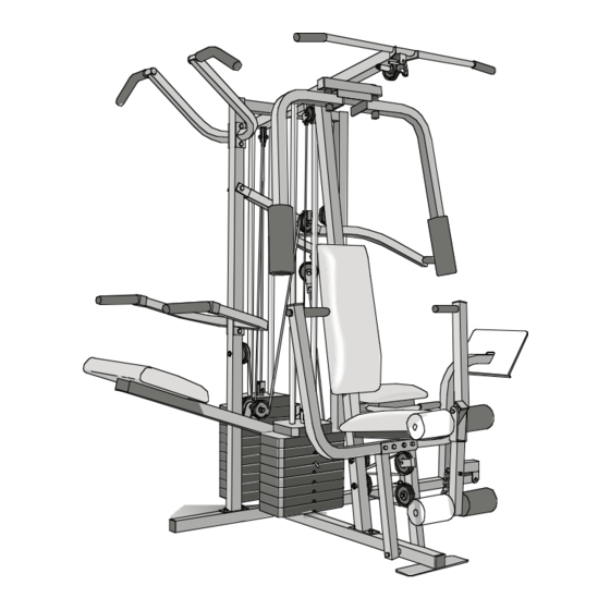
Page 3: Before You Begin
The model number is 831.159380. The serial number can be found on a decal attached to the WEIDER PRO 9645 (see the front cover of this manual). Before reading further, please review the drawing below and familiarize yourself with the parts that are labeled. -
Page 4: Assembly
ASSEMBLY Before beginning assembly, carefully read the following information and instructions: • Place all parts of the PRO 9645 in a cleared area and remove the packing materials; do not dispose of the packing materials until assembly is com- pleted. •... - Page 5 2. Slide the Assist Upright (74) and the Leg Press Upright (56) onto the indicated 5/16” x 2 1/2” Carriage Bolts (1) in the Stabilizer (5). The high side of the brackets on the Assist Upright and Leg Press Upright should be on the side shown.
- Page 6 4. Press a 2” Square Inner Cap (27) into the end of the Top Frame (55). Press a 1 3/4” Square Inner Cap (44) into each end of the crossbar on the Top Frame. Press two 1” Round Inner Caps (49) into the top of the crossbar. Attach the Top Frame (55) to the Assist Upright (74) and the Leg Press Upright (56) with two 5/16”...
- Page 7 7. Press a Weight Tube Bumper (64) into the end of the Short Weight Tube (108). Insert the Weight Tube into the front stack of Weights (25). Be sure that the pin on the Weight Tube is sitting in the pin grooves in the top Weight.
- Page 8 9. Attach the upper ends of the Short Weight Guides (73) to the Top Frame (55) with a 5/16” x 6” Bolt (60), two 1/2” x 3/4” Spacers (61), and a 5/16” Nylon Locknut (3). Attach the upper ends of the Long Weight Guides (62) to the Top Frame (55) in the same manner.
- Page 9 12. Press a 1” Round Inner Cap (49) into one of the Press Arms (46). Press a 1 3/4” Square Inner Cap (44) into the Press Arm. Attach the Press Arm (46) to one side of the Press Frame (17) with two 5/16” x 2 1/2” Bolts (22) and two 5/16”...
- Page 10 15. See the inset drawing. Attach the Military Press Arm (84) to the Pivot Arm (101) with two 5/16” x 2 1/4” Bolts (33) and two 5/16” Nylon Locknuts (3). Press two 1 1/2” Square Inner Caps (32) into the Military Press Arm (84). Press two 1” Round Inner Caps (49) into the Military Press Arm.
- Page 11 17. Attach the Left Pull-up Arm (75) and the Right Pull-up Arm (77) to the Assist Upright (74) with two 5/16” x 2 3/4” Bolts (11) and two 5/16” Nylon Locknuts (3). Attach the Left Dip Arm (78) and the Right Dip Arm (79) to the Assist Upright (74) with two 5/16”...
- Page 12 20. Wrap the High Cable (58) around a “V”-Pulley (50). Attach the “V”-Pulley and a Long Cable Trap (31) to the indicated bracket on the Front Upright (42) with a 3/8” x 2 1/2” Bolt (86) and a 3/8” Nylon Locknut (21). Be sure that the Long Cable Trap is positioned to hold the Cable in place.
- Page 13 24. See the inset drawing. Attach a 3 1/2” Pulley (15) and a Cable Trap (66) to the upper hole in a Long “U”-Bracket (57) with a 3/8” x 2” Bolt (12) and a 3/8” Nylon Locknut (21). Be sure that the Cable Trap is inside the Long “U”- Bracket.
- Page 14 27. Locate the Low Cable (23). Route the Low Cable under the 3 1/2” Low Pulley (102). Be sure that the end of the Cable with the ball is on the indicated side of the Press Frame (17) and that the Cable is between the Pulley and the crossbar on the Press Frame.
- Page 15 31. Attach the end of the Low Cable (23) to the Long “U”-Bracket (57) with a 1/4” Nylon Locknut (2) and a 1/4” Flat Washer (10). Do not completely tighten the Nylon Locknut. It should be threaded onto the end of the Cable so only a couple of threads are showing above the Nylon Locknut, as shown in the inset drawing.
- Page 16 34. Wrap the Military Press Cable (72) around a “V”-Pulley (50). Attach the “V”-Pulley to the Top Frame (55) with a 3/8” x 2 1/2” Bolt (86) and a 3/8” Nylon Locknut (21). Wrap the Military Press Cable (72) around a 3 1/2”...
- Page 17 36. Slide a 5/16” Flat Washer (8) onto a 5/16” x 2 3/4” Bolt (11). Insert the Bolt through the indi- cated hole in the Pivot Arm (101). The Bolt must be inserted from the side shown. Fully tighten a 5/16” Nylon Jam Nut (93) onto the Bolt.
- Page 18 38. Locate the Leg Press Cable (99). Attach the end of the Leg Press Cable to the Long “U”- Bracket (57) with a 1/4” Nylon Locknut (2) and a 1/4” Flat Washer (10). Do not completely tighten the Nylon Locknut. It should be threaded onto the end of the Cable only a couple of turns, as shown in the inset drawing.
- Page 19 40. Locate and open the parts bag labeled “SEAT ASSEMBLY.” Insert a 1/4” x 2 1/2” Carriage Bolt (92) through the center hole in a Seat Plate (37). Attach the Seat Plate to the Rear Backrest (85) with two 1/4” x 1/2” Screws (18). Insert the 1/4”...
- Page 20 43. Attach the Front Backrest (41) to the Front Upright (42) with two 1/4” x 2 1/2” Screws (43) and two 1/4” Flat Washers (10). The Backrest must be oriented as shown. 44. Press a 1 1/2” Square Inner Cap (32) into the Front Seat Frame (36).
- Page 21 47. Press two 3/4” Round Inner Caps (34) into each Pad Tube (28). Insert a Pad Tube (28) into the Front Seat Frame (36). Slide a Foam Pad (30) onto each end of the Pad Tube. Insert the other Pad Tube (28) into the Leg Lever (29).
-
Page 22: How To Use The Home Gym System
HOW TO USE THE HOME GYM SYSTEM The instructions below describe how each part of the home gym system can be adjusted. Refer to the exercise poster accompanying this manual to see how the home gym system should be set up for each exercise. IMPOR- TANT: When attaching the lat bar or nylon strap, make sure that the attachments are in the correct start- ing position for the exercise to be performed. - Page 23 ATTACHING AND REMOVING THE SEAT To attach the Seat (13), set the bracket on the Front Seat Frame (36) onto the indicated pins on the Front Upright (42). Attach the Front Seat Frame to the Front Upright with the 5/16” x 2 3/4” Carriage Bolt (14) and the Seat Knob (40).
-
Page 24: Weight Resistance Chart
WEIGHT RESISTANCE CHART This chart shows the approximate weight resistance at each weight station. “Top” refers to the 6.5 lb. top weight. The other numbers refer to the 12.5 lb. weight plates. The butterfly arm resistance listed is the resistance for each butterfly arm. -
Page 25: Trouble-Shooting And Maintenance
TROUBLE-SHOOTING AND MAINTENANCE Inspect and tighten all parts each time you use the home gym system. Replace any worn parts immediately. The home gym system can be cleaned using a damp cloth and mild non-abrasive detergent. Do not use solvents. TIGHTENING THE CABLES Woven cable, the type of cable used on the home gym system, can stretch slightly when it is first used. -
Page 26: Cable Diagrams
CABLE DIAGRAMS The cable diagrams on these pages show the proper routing of the High Cable (58), the Low Cable (23), the Military Press Cable (72), and the Leg Press Cable (99). Use the diagrams to be sure that the four cables and the cable traps have been assembled correctly. - Page 27 Military Press Cable (72) and Leg Press Cable (99) Military Press Cable (72) 8—Pivot Arm 1—Long “U”-Bracket Rear Weight Stack—1 4—Rear Seat Frame Leg Press Cable (99)
- Page 28 5/16" x 2" Eyebolt (35)—1 1/2" x 3/4" Spacer (61)–4 5/8" x 9/16" Spacer (7)–1 3/4" Round Inner Cap (34)–4 1" Round Inner Cap (49)–6 1" Round Cover Cap (70)–2 1 1/2" Square Inner Cap (32)–4 1" Square Inner Cap (6)–1 1"...
- Page 29 1/4" Nylon Locknut (2)–6 5/16" Nylon Locknut (3)–36 5/16" Nylon Jam Nut (93)–4 3/8" Nylon Locknut (21)–23 1/4" Flat W asher (10)–15 5/16" Flat Washer (8)–9 3/8" Flat Washer (9)–9 1/4" x 2" Machine Screw (81)–1 1/4" x 2 1/2" Carriage Bolt (92)–1 5/16"...
- Page 30 5/16" x 3" Bolt ( 111)–1 3/8" x 3 1/4" Bolt (67)–2 3/8" x 3 1/2" Bolt (16)–1 1/4" x 1/2" Screw (18)–6 3/8" x 3 3/4" Bolt (88)–6 5/16" x 5" Bolt (68)–1 Cable Clip (53)–3 1" Retainer (69)–4 1 1/8"...
- Page 31 PART LIST—Model No. 831.159380 Part Qty. Description 100291 5/16” x 2 1/2” Carriage Bolt 012139 1/4” Nylon Locknut 012056 5/16” Nylon Locknut 133351 Base 133352 Stabilizer 120696 1” Square Inner Cap 121845 5/8” x 9/16” Spacer 014073 5/16” Flat Washer 014132 3/8”...
- Page 32 EXPLODED DRAWING—Model No. 831.159380 R1096A...
-
Page 33: Full 90 Day Warranty
SEARS, ROEBUCK AND CO., DEPT. 817WA, HOFFMAN ESTATES, IL 60179 Part No. 133393 R1096A The model number and serial number of your WEIDER are listed on a decal attached to the frame. See the front cover of this manual to find the location of the decal.