Advertisement
Advertisement
Table of Contents

Related Manuals for Weider PRO 270 L


Summary of Contents for Weider PRO 270 L
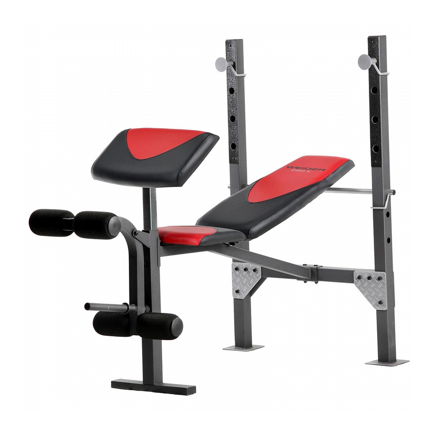
- Page 1 Model No. 831.15907.0 Serial No. WEIGHT BENCH EXERCISER Write the serial number in the space above for reference. User's Manual Serial Number Decal (under the seat) • Assembly • Operation • Maintenance • Part List and Drawing Sears, Roebuck and Co. Hoffman Estates, IL 60179...
-
Page 2: Warning Decal Placement
TABLE OF CONTENTS WARNING DECAL PLACEMENT .............. IMPORTANT PRECAUTIONS ..............BEFORE YOU BEGIN ............... PART IDENTIFICATION CHART ............... ASSEMBLY ................ADJUSTMENT ................EXERCISE GUIDELINES ..............PART LIST ................EXPLODED DRAWING ..............ORDERING REPLACEMENT PARTS ..........Back Cover 90 DAY FULL WARRANTY ............ -
Page 3: Important Precautions
IMPORTANT PRECAUTIONS WARNING: To reduce the risk of serious injury, read all important precautions and instructions in this manual and all warnings on your weight bench before using your weight bench. Sears assumes no responsibility for personal injury or property damage sustained by or through the use of this product. -
Page 4: Before You Begin
BEFORE YOU BEGIN Thank you for selecting the new WELDER PRO reading this manual, please see the back cover of this 270 L weight bench. The 270 L weight bench offers a manual. To help us assist you, note the product model selection of exercises designed to develop the major number and serial number before contacting us. -
Page 5: Part Identification Chart
PART IDENTIFICATION CHART Refer to the drawings below to identify small parts used in assembly. The number in parentheses by each draw- ing is the key number of the part, from the PART LIST near the end of this manual. IMPORTANT" If you cannot find a part in the hardware kit, check to see if it has been preassembled. -
Page 6: Assembly
ASSEMBLY Assembly requires two persons. The following tools (not included) may be required for assembly: Because of its size and weight, assemble the weight bench in the location where it will be two adjustable wrenches used. Make sure that there is enough clear- one rubber mallet ance to walk around the weight bench as you assemble it. - Page 7 Attach one end of the Crossbar (2) to two Joint Plates (35, 41) with two M10 x 68mm Bolts (27) and two M10 Locknuts (31). Do not tighten the Locknuts yet. Attach the other end of the Crossbar (2) in the same way.
- Page 8 Attach the Frame (3) to the Crossbar (2) with two M10 x 68mm Bolts (27) and two M10 Locknuts (31). Do not tighten the Locknuts yet. Insert the Backrest Support (14) from the direc- tion shown into one of the three sets of holes in the Uprights (1).
- Page 9 Insert a Pad Tube (12) through the Leg Lever (6). Slide a Foam Pad (13) onto each end of the Pad Tube (12). Press a Pad Cap (34) into each end of the Pad Tube (12). Repeat this step with the other Pad Tube (12), Foam Pads (13), and Pad Caps (34).
- Page 10 11. Apply grease to an M10 x 135mm Bolt (23). Attach the Backrest Tubes (7) to the welded tube on the Frame (3) with the M10 x 135mm Bolt (23), two M10 Washers (30), and an M10 Locknut (31). Do not overtighten the Locknut;...
-
Page 11: Adjustment
ADJUSTMENT The weight bench is designed to be used with your own weight set (not included). The steps below explain how the weight bench can be adjusted. See EXERCISE GUIDELINES on page 13 for important exercise information, and refer to the accompanying exercise guide to see the correct form for several exercises. Refer also to the exercise information accompanying your weight set for additional exercises. - Page 12 ADJUSTING THE WEIGHT RESTS To change the height of the Weight Rests (15), remove them from the Uprights (1) and insert them Locking into a different set of holes in the Uprights. Rotate the Weight Rests so that the locking pins are wrapped around the Uprights.
-
Page 13: Exercise Guidelines
EXERCISE GUIDELINES FOUR TYPES OF STRENGTH WORKOUTS to determine the appropriate length of time for each workout, and the numbers of repetitions and sets to Note: A "repetition" is one complete cycle of an exer- complete. Progress at your own pace and be sensitive cise, such as one sit-up. -
Page 14: Part List
PART LIST--Model No. 831.15907.0 R0610A Key No. Qty. Description Key No. Qty. Description Upright M10 x 135mm Bolt Crossbar M6 x 16mm Screw Frame M10 x 60mm Bolt Front Leg 25mm x 50mm Inner Cap Curl Pad M10 x 68mm Bolt Leg Lever M8 x 45mm Bolt Backrest Tube... -
Page 15: Exploded Drawing
EXPLODED DRAWING--Model No. 831.15907.0 R0610A <... -
Page 16: 90 Day Full Warranty
Your Home For repair--in your home--of all major brand appliances, lawn and garden equipment, or heating and cooling systems, no matter made it, no matter sold it! For the replacement parts, accessories, and user's manuals that you need to do-it-yourself. For Sears professional installation of home appliances...