Table of Contents
Advertisement
Quick Links
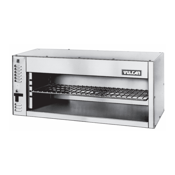
1024, 1036, 1048 CHEESEMELTER
MODELS
1024C
1024W
1024P
1036C
1036W
1036P
1048C
1048W
1048P
For additional information on Vulcan-Hart or to locate an authorized parts
and service provider in your area, visit our website at www.vulcanhart.com
VULCAN-HART
DIVISION OF ITW FOOD EQUIPMENT GROUP, LLC
WWW.VULCANHART.COM
ML-103833
ML-103834
ML-103835
ML-103836
ML-103837
ML-103838
ML-103839
ML-103840
ML-103841
PARTS MANUAL
Model 1036W
P.O. BOX 696, LOUISVILLE, KY 40201-0696
– 1 –
SERVICE &
TEL. (800) 814-2028
FORM 31087 Rev. B (June 2006)
Advertisement
Table of Contents

Related Manuals for Vulcan-Hart 024C ML-103833


Summary of Contents for Vulcan-Hart 024C ML-103833
- Page 1 1048C ML-103839 1048W ML-103840 1048P ML-103841 For additional information on Vulcan-Hart or to locate an authorized parts and service provider in your area, visit our website at www.vulcanhart.com VULCAN-HART DIVISION OF ITW FOOD EQUIPMENT GROUP, LLC WWW.VULCANHART.COM SERVICE & PARTS MANUAL Model 1036W P.O.
-
Page 2: Parts Replacement
WARNING: DISCONNECT THE ELECTRICAL POWER TO THE MACHINE AND FOLLOW THE LOCKOUT / TAGOUT PROCEDURES. HEATER (Fig. 1) 1. Push one end of the heater into one socket as far as it will go. 2. Swing the other end of heater up until it lines up with the opposite socket. 3. -
Page 3: Component Replacement
COMPONENT REPLACEMENT 1. Remove the access panel on the left side. 2. Remove all screws holding down the cover. 3. Lift cover straight up. Replacement of the voltage regulator, actuating switch, main terminal block, or the contactor (1048 only) will require removing the component mounting plate. 1. - Page 4 COMPONENT LOCATION DRAWING SOCKETS CONTACTOR (1048) VOLTAGE REGULATOR PILOT LIGHT SWITCH COMPONENT MOUNTING PLATE COOLING TERMINAL NYLON ACTUATING BLOCK LOOP SWITCH GROUND STUD COMPONENT LOCATION (VIEW OF LEFT SIDE WITH COVER REMOVED) – 4 –...
-
Page 5: Troubleshooting
(See component location drawing on page 4.) WARNING: DISCONNECT THE ELECTRICAL POWER TO THE MACHINE AND FOLLOW THE LOCKOUT / TAGOUT PROCEDURES. IF THE UNIT BLOWS A FUSE OR TRIPS A CIRCUIT BREAKER 1. Check the capacity of the circuit. 2. - Page 6 ELECTRICAL SCHEMATIC 1024 & 1036 HEATERS VOLTAGE REGULATOR ACTUATING SWITCH LIGHT PILOT MAIN SWITCH TERMINAL BLOCK GROUND – 6 –...
- Page 7 ELECTRICAL SCHEMATIC 1048 LEFT SIDE HEATERS RIGHT SIDE HEATERS VOLTAGE REGULATOR ACTUATING SWITCH LEFT RIGHT PILOT PILOT LIGHT LIGHT LEFT RIGHT SWITCH SWITCH MAIN PILOT LIGHT CONTACTOR 1048 SCHEMATIC MAIN SWITCH TERMINAL BLOCK GROUND STUD – 7 –...
- Page 8 ITEM DESCRIPTION Heater (208V) Heater (240V) Heater Socket Pilot Light Main Switch Left/Right Heat Switch Contactor Terminal Block Voltage Regulator Cooling Fan Fan Guard Actuating Switch Counter Leg—Thermoplastic Rack Outside Cover Mounting Screws Heat Shield/Deflector Ceramic Wire Nuts Rack Stop Access/Control Box Cover Access Panel Screws LH Pivot (2 Position)
-
Page 9: Recommended Spare Parts List
RECOMMENDED SPARE PARTS LIST PART 825536 Heater (208V) 1024 ... 2 825331 Heater (208V) 1036 ... 2 825300 Heater (208V) 1048 ... 2 825538 Heater (240V) 1024 ... 2 825332 Heater (240V) 1036 ... 2 825301 Heater (240V) 1048 ... 2 825098 Heater Socket ...