Juniper PTX1000 Hardware Manual
Packet transport router
Hide thumbs
Also See for PTX1000:
- Hardware manual (150 pages) ,
- Quick start manual (7 pages) ,
- Quick start (2 pages)
Table of Contents
Advertisement
Quick Links
Advertisement
Table of Contents
Troubleshooting

Related Manuals for Juniper PTX1000


Summary of Contents for Juniper PTX1000
- Page 1 PTX1000 Packet Transport Router Hardware Guide Published 2020-06-02...
- Page 2 END USER LICENSE AGREEMENT The Juniper Networks product that is the subject of this technical documentation consists of (or is intended for use with) Juniper Networks software. Use of such software is subject to the terms and conditions of the End User License Agreement (“EULA”) posted at https://support.juniper.net/support/eula/.
-
Page 3: Table Of Contents
Self-Help Online Tools and Resources | xv Creating a Service Request with JTAC | xv Overview PTX1000 System Overview | 17 PTX1000 Packet Transport Router Description | 17 Benefits of the PTX1000 Router | 18 Port Panel and Management Panel | 19 FRU Panel | 20... - Page 4 PTX1000 Environmental Requirements and Specifications | 52 General Site Guidelines | 53 PTX1000 Chassis Grounding Cable and Lug Specifications | 53 PTX1000 Clearance Requirements for Airflow and Hardware Maintenance | 54 PTX1000 Physical Specifications | 55 Site Electrical Wiring Guidelines | 56...
- Page 5 How to Calculate Power Margin for Fiber-Optic Cable | 67 PTX1000 Management Cable Specifications and Pinouts | 69 Cable Specifications for Console and Management Connections for the PTX1000 | 69 Management Port Connector Pinouts for the PTX1000 | 70 Console Port Connector Pinouts for the PTX1000 | 70...
- Page 6 Returning the Chassis or Components Returning the PTX1000 Chassis or Components | 121 Locating the Serial Number on a PTX1000 Chassis or Component | 121 Listing the Chassis and Component Details by Using the CLI | 122 Locating the Chassis Serial Number ID Label on a PTX1000 | 123...
- Page 7 Locating the Serial Number ID Labels on FRU Components | 123 How to Contact Customer Support to Obtain Return Material Authorization | 123 Packing a PTX1000 Chassis or Component for Shipping | 124 Packing a PTX1000 for Shipping | 124...
- Page 8 Lightning Activity Warning | 157 Operating Temperature Warning | 158 Product Disposal Warning | 160 PTX1000 Compliance Statements for Acoustic Noise | 161 Action to Take After an Electrical Accident | 161 Prevention of Electrostatic Discharge Damage | 161 AC Power Electrical Safety Guidelines | 163...
-
Page 9: About The Documentation
If the information in the latest release notes differs from the information in the documentation, follow the product Release Notes. Juniper Networks Books publishes books by Juniper Networks engineers and subject matter experts. These books go beyond the technical documentation to explore the nuances of network architecture, deployment, and administration. -
Page 10: Merging A Full Example
If the example configuration contains the top level of the hierarchy (or multiple hierarchies), the example is a full example. In this case, use the load merge command. If the example configuration does not start at the top level of the hierarchy, the example is a snippet. In this case, use the load merge relative command. -
Page 11: Merging A Snippet
Merging a Snippet To merge a snippet, follow these steps: 1. From the HTML or PDF version of the manual, copy a configuration snippet into a text file, save the file with a name, and copy the file to a directory on your routing platform. For example, copy the following snippet to a file and name the file ex-script-snippet.conf. - Page 12 Table 1: Notice Icons Icon Meaning Description Informational note Indicates important features or instructions. Caution Indicates a situation that might result in loss of data or hardware damage. Warning Alerts you to the risk of personal injury or death. Laser warning Alerts you to the risk of personal injury from a laser.
- Page 13 xiii Table 2: Text and Syntax Conventions (continued) Convention Description Examples Italic text like this Represents variables (options for Configure the machine’s domain which you substitute a value) in name: commands or configuration [edit] statements. root@# set system domain-name domain-name Text like this Represents names of configuration To configure a stub area, include...
-
Page 14: Documentation Feedback
URL or page number, and software version (if applicable). Requesting Technical Support Technical product support is available through the Juniper Networks Technical Assistance Center (JTAC). If you are a customer with an active Juniper Care or Partner Support Services support contract, or are... -
Page 15: Self-Help Online Tools And Resources
JTAC hours of operation—The JTAC centers have resources available 24 hours a day, 7 days a week, 365 days a year. Self-Help Online Tools and Resources For quick and easy problem resolution, Juniper Networks has designed an online self-service portal called the Customer Support Center (CSC) that provides you with the following features: Find CSC offerings: https://www.juniper.net/customers/support/... -
Page 16: Overview
C HAPTER Overview PTX1000 System Overview | 17 PTX1000 Port Panel | 23 PTX1000 Management Panel | 32 PTX1000 Cooling System | 36 PTX1000 Power System | 39... -
Page 17: Ptx1000 System Overview
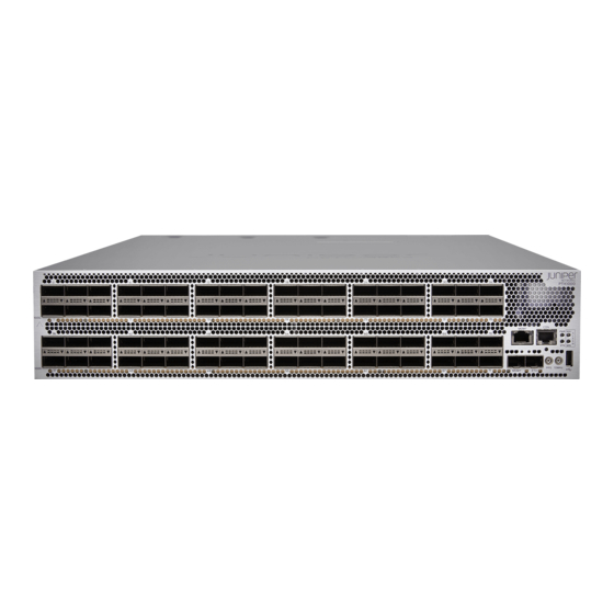
Port Panel and Management Panel | 19 FRU Panel | 20 The Juniper Networks PTX1000 Packet Transport Router is a fixed-configuration router that supports 10-Gbps, 40-Gbps, and 100-Gbps port speeds in a compact 2U form factor, enabling service providers to organically distribute peering points throughout the network. -
Page 18: Benefits Of The Ptx1000 Router
In addition, the 64-GB SSDs support enhanced hardware resiliency through storage partitioning and redundancy. Earlier versions of the PTX1000 have 2 x 32-GB M.2 SATA SSDs. PTX1000 routers with 32-GB SSDs do not support the request vmhost snapshot and request vmhost snapshot recovery commands, and do not support enhanced hardware resiliency. -
Page 19: Port Panel And Management Panel
Port Panel and Management Panel The port panel of the PTX1000 contains 72 network ports and port LEDs. The management panel of the PTX1000 contains console and management ports, a reset button, system status LEDs, clocking ports, and a USB port. -
Page 20: Fru Panel
Fan modules (3) — The cooling system in a PTX1000 consists of three 80-W fan modules that operate at 150 cubic feet per minute (CFM) at full speed as well as fans housed in the power supplies. Each fan module has dual counter-rotating fans. -
Page 21: Ptx1000 Hardware Component Overview
Cooling system—The PTX1000 has three fan modules. Each fan module is a redundant unit containing two fans. If a fan module fails and the remaining fan modules are unable to keep the PTX1000 within the desired temperature thresholds, chassis alarms are raised and the PTX1000 might shut down. -
Page 22: Ptx1000 Field-Replaceable Units
Do not connect feed A and feed B to the same power supply input terminal. PTX1000 Field-Replaceable Units Field-replaceable units (FRUs) are components that you can replace at your site. The PTX1000 FRUs are hot-removable and hot-insertable—you can remove and replace them without powering off the PTX1000 or disrupting the routing function. -
Page 23: Ptx1000 Port Panel
— — NOTE: If you have a Juniper Care service contract, register any addition, change, or upgrade of hardware components at https://www.juniper.net/customers/support/tools/updateinstallbase/ . Failure to do so can result in significant delays if you need replacement parts. This note does not apply if you replace existing components with the same type of component. - Page 24 The PTX1000 supports 10-Gbps, 40-Gbps, and 100-Gbps port speeds. Figure 4 on page 24 shows the PTX1000 port panel and management panel. Figure 4: PTX1000 Port Panel and Management Panel Port panel Management panel — — Each of the 72 network ports on the port panel supports quad small form-factor pluggable plus (QSFP+) transceivers.
-
Page 25: Example: Using Network Ports As 40-Gigabit Ethernet Interfaces
Example: Using Network Ports as 40-Gigabit Ethernet Interfaces All network ports on the PTX1000 can be configured as 40-Gigabit Ethernet interfaces. You must configure 40-Gigabit Ethernet interfaces in groups of three network ports. When the port speed is configured as 40 Gbps on the first port in a port group, all three ports in the port group operate at 40 Gbps. -
Page 26: Ptx1000 Port Mapping
Ethernet-capable port—use the set chassis fpc 0 pic 0 port 1 speed 100g command. After you commit this configuration, port 1 operates at 100 Gbps, while ports 0 and 2 are disabled. PTX1000 Port Mapping Table 6 on page 27 shows the available combinations for the network ports on the PTX1000. - Page 27 Table 6: PTX1000 Port Mapping 4 x 10-Gigabit 40-Gigabit Ethernet Ethernet Ports Disabled When a Channelized Ports Port 100-Gigabit 100-Gigabit Ethernet Port Number (Default) Groups Ethernet Ports Interface Is Configured – – 0, 2 – – – – – –...
- Page 28 Table 6: PTX1000 Port Mapping (continued) 4 x 10-Gigabit 40-Gigabit Ethernet Ethernet Ports Disabled When a Channelized Ports Port 100-Gigabit 100-Gigabit Ethernet Port Number (Default) Groups Ethernet Ports Interface Is Configured – – 18, 20 – – – – –...
- Page 29 Table 6: PTX1000 Port Mapping (continued) 4 x 10-Gigabit 40-Gigabit Ethernet Ethernet Ports Disabled When a Channelized Ports Port 100-Gigabit 100-Gigabit Ethernet Port Number (Default) Groups Ethernet Ports Interface Is Configured – – 36, 38 – – – – –...
- Page 30 Table 6: PTX1000 Port Mapping (continued) 4 x 10-Gigabit 40-Gigabit Ethernet Ethernet Ports Disabled When a Channelized Ports Port 100-Gigabit 100-Gigabit Ethernet Port Number (Default) Groups Ethernet Ports Interface Is Configured – – 54, 56 – – – – –...
-
Page 31: Ptx1000 Network Port Leds
PTX1000 Network Port LEDs Each PTX1000 network port uses a single bicolored LED to indicate link status and activity. The triangular LEDs are located between the top row and bottom row of ports. The LEDs are shaped so that each LED points to the port with which it is associated. -
Page 32: Ptx1000 Management Panel
— — You manage the PTX1000 by using the Junos OS CLI, which is accessible through the console and out-of-band management ports on the management panel. In addition, the management panel has system status LEDs that alert you to minor or major alarms or other issues with the router, external clock synchronization ports, and a USB port to support software installation and recovery. -
Page 33: Ptx1000 Management Port Leds
Junos OS CLI, this port is identified as em1. PTX1000 Management Port LEDs There are two management ports on the PTX1000, located on the management panel next to the network ports. Both ports are labeled MGMT. The RJ-45 management port is for 10/100/1000BASE-T connections and the small form-factor pluggable (SFP) management port is for 10/100/1000BASE-T and 1000BASE-X connections. - Page 34 Figure 11: Management Port LEDs on a PTX1000 Status LED (RJ-45) Link activity LED (SFP) — — Link activity LED (RJ-45) — Table 8 on page 34 describes the RJ-45 management port LEDs. Table 8: PTX1000 RJ-45 Management Port LEDs...
-
Page 35: Ptx1000 Chassis Status Leds
PTX1000 Chassis Status LEDs The PTX1000 has four status LEDs on the management panel of the chassis, next to the network ports (see Figure 12 on page 35). Figure 12: Chassis Status LEDs on a PTX1000 Power (PWR) LED Minor alarm (MIN) LED —... -
Page 36: Ptx1000 Cooling System
Fan Modules The cooling system in a PTX1000 consists of three 80-W fan modules that operate at 150 cubic feet per minute (CFM) at full speed as well as fans housed in the power supplies. Each fan module has dual counter-rotating fans. -
Page 37: Airflow Through The Chassis
Airflow Through the Chassis In the PTX1000 cooling system, cool air enters through the vents in the port panel and hot air exhausts through the FRU panel. This type of airflow is known as airflow out or port-to-FRU airflow. When the chassis is installed, it must be positioned so that the FRUs are next to the hot aisle. -
Page 38: Ptx1000 Fan Module Leds
PTX1000 Fan Module LEDs The PTX1000 has status LEDs for each fan module on the left side of the corresponding fan module slot. Figure 16 on page 39 shows the location of the LED next to the fan module on the PTX1000 FRU panel. -
Page 39: Ptx1000 Power System
Figure 16: Fan Module LEDs on a PTX1000 Status LEDs — Table 11 on page 39 to interpret the state of the fan module LED. Table 11: PTX1000 Fan Module LED Name Color State Description Status Green On steadily The fan module is operating normally. The system has verified that the module is engaged, and that the fan is operating correctly. -
Page 40: Ptx1000 Ac Power Supply Description
12 VDC. A PTX1000 provides for twice the number of power supplies needed to power all of the components in the device, which is known as 2N redundancy. When the PTX1000 has all four power supplies installed and connected to power, the router has full power redundancy. If a power... -
Page 41: Ptx1000 Dc Power Supply Description
42) are hot-removable and hot-insertable field-replaceable units (FRUs) that you can install without powering off the router or disrupting the routing function. The PTX1000 has four power supplies. CAUTION: Do not mix AC and DC power supplies in the same chassis. - Page 42 12 VDC. A PTX1000 provides for twice the number of power supplies needed to power all of the components in the router, which is known as 2N redundancy. When the PTX1000 has all four power supplies installed and connected to power, the router has full power redundancy. If a power supply fails or is removed, another power supply balances the electrical load without interruption.
-
Page 43: Ptx1000 Power Supply Leds
PTX1000 Power Supply LEDs Each PTX1000 power supply has a status LED on the power supply faceplate. Figure 21 on page 43 shows the location of the LED on a PTX1000 AC power supply and Figure 22 on page 43 shows the location of the LED on a PTX1000 DC power supply. -
Page 44: Ptx1000 Ac Power Specifications
PTX1000 AC Power Specifications Table 13 on page 44 describes the AC power specifications for a PTX1000. Table 13: PTX1000 AC Power Specifications Item Specifications AC input voltage Operating range: 100–240 VAC... -
Page 45: Ptx1000 Ac Power Cord Specifications
Table 13: PTX1000 AC Power Specifications (continued) Item Specifications Maximum power consumption 1425 W PTX1000 AC Power Cord Specifications Detachable AC power cords are shipped with the chassis if you include them as part of your order. The coupler is type C13 as described by International Electrotechnical Commission (IEC) standard 60320. The plug at the male end of the power cord fits into the power source outlet that is standard for your geographical location. -
Page 46: Ptx1000 Dc Power Specifications
CBL-EX-PWR-C13-UK PTX1000 DC Power Specifications Table 15 on page 47 describes the DC power specifications for a PTX1000. NOTE: We recommend that the 48-VDC facility DC source be equipped with a circuit breaker rated at 40 A (–48 VDC) minimum, or as required by local code. -
Page 47: Ptx1000 Dc Power Cable Specifications
“Connecting the PTX1000 to Ground” on page DC power cables, each approximately 13.1 ft (4 m) long, are supplied with the PTX1000. The provided cables include the three-pin connector on one end and insulated wires at the opposite end, for connection to the site’s DC power distribution system. - Page 48 WARNING: For field-wiring connections, use copper conductors only. WARNING: Power cables must not block access to PTX1000 components or drape where people could trip over them. CAUTION: You must ensure that power connections maintain the proper polarity. The power source cables might be labeled (+) and (–) to indicate their polarity. There is no standard color coding for DC power cables.
-
Page 49: Site Planning, Preparation, And Specifications
C HAPTER Site Planning, Preparation, and Specifications PTX1000 Site Preparation Checklist | 50 PTX1000 Site Guidelines and Requirements | 51 PTX1000 Network Cable and Transceiver Planning | 58 PTX1000 Management Cable Specifications and Pinouts | 69... -
Page 50: Ptx1000 Site Preparation Checklist
Power Measure the distance between external power sources and the router installation site. Calculate the power PTX1000 AC Power Specifications on page 44 consumption and PTX1000 DC Power Specifications on page 46 requirements. Rack Verify that your rack meets “PTX1000 Rack Requirements” on page 56... -
Page 51: Ptx1000 Site Guidelines And Requirements
PTX1000 Environmental Requirements and Specifications | 52 General Site Guidelines | 53 PTX1000 Chassis Grounding Cable and Lug Specifications | 53 PTX1000 Clearance Requirements for Airflow and Hardware Maintenance | 54 PTX1000 Physical Specifications | 55 Site Electrical Wiring Guidelines | 56... -
Page 52: Ptx1000 Environmental Requirements And Specifications
PTX1000 Environmental Requirements and Specifications The PTX1000 must be installed in a rack. It must be housed in a dry, clean, well-ventilated, and temperature-controlled environment. Follow these environmental guidelines: The site must be as dust-free as possible, because dust can clog air intake vents and filters, reducing the efficiency of the PTX1000 cooling system. -
Page 53: General Site Guidelines
Install the device in a secure area, so that only authorized personnel can access the device. PTX1000 Chassis Grounding Cable and Lug Specifications For installations that require a separate grounding conductor to the chassis, the PTX1000 must be adequately grounded before power is connected to ensure proper operation and to meet safety and electromagnetic interference (EMI) requirements. -
Page 54: Ptx1000 Clearance Requirements For Airflow And Hardware Maintenance
14–6 AWG (2–13.3 mm²) stranded wire. The grounding cable that you provide for a PTX1000 must be the same size or heavier than the input wire of each power supply. Minimum recommendations are 8 AWG (8.4 mm²) stranded wire, 60° C wire, or as permitted by local code. -
Page 55: Ptx1000 Physical Specifications
You must leave at least 24 in. (61 cm) both in front of and behind the PTX1000 for service personnel to remove and install hardware components, you must leave adequate space at the front and back of the PTX1000. -
Page 56: Site Electrical Wiring Guidelines
Destruction of the signal drivers and receivers in the device Electrical hazards as a result of power surges conducted over the lines into the equipment PTX1000 Rack Requirements The PTX1000 chassis is designed to be installed in four-post racks. Rack requirements consist of:... - Page 57 (document number EIA-310–D) published by the Electronics Components Industry Association (http://www.ecianow.org/). Mounting bracket The holes in the mounting brackets are spaced at 1 U (1.75 in. or 4.45 cm), so that the PTX1000 hole spacing can be mounted in any rack that provides holes spaced at that distance.
-
Page 58: Ptx1000 Network Cable And Transceiver Planning
Determining Transceiver Support for the PTX1000 The PTX1000 has 72 network ports. Each of the 72 network ports on the port panel supports quad small form-factor pluggable plus (QSFP+) transceivers, and is configured as a channelized 4 x 10-Gigabit Ethernet interface by default (for a maximum of 288 10-Gigabit Ethernet ports). -
Page 59: Cable And Connector Specifications For Mx And Ptx Series Devices
Tool enables you to search by product, displaying all the transceivers supported on that device, or category, by interface speed or type. The list of supported transceivers for the PTX1000 is located at https://pathfinder.juniper.net/hct/product/#prd=PTX1000. CAUTION: If you face a problem running a Juniper Networks device that uses a third-party optic or cable, the Juniper Networks Technical Assistance Center (JTAC) can help you diagnose the source of the problem. -
Page 60: 12-Fiber Mpo Connectors
12-Fiber MPO Connectors There are two types of cables used with 12-fiber MPO connectors on Juniper Networks devices—patch cables with MPO connectors on both ends, and breakout cables with an MPO connector on one end and four LC duplex connectors on the opposite end. Depending on the application, the cables might use single-mode fiber (SMF) or multimode fiber (MMF). - Page 61 Table 22: Cable Signals for 12-Fiber Ribbon Patch Cables (continued) Fiber Signal Rx3 (Receive) Rx2 (Receive) Rx1 (Receive) Rx0 (Receive) Table 23: Cable Pinouts for 12-Fiber Ribbon Patch Cables MPO Pin MPO Pin 12-Fiber Ribbon Breakout Cables with MPO-to-LC Duplex Connectors You can use 12-ribbon breakout cables with MPO-to-LC duplex connectors to connect a QSFP+ transceiver to four separate SFP+ transceivers—for example, 4x10GBASE-LR-to-10GBASE-LR or...
- Page 62 4x10GBASE-SR-to-10GBASE-SR SFP+ transceivers. The breakout cable is constructed out of a 12-fiber ribbon fiber-optic cable. The ribbon cable splits from a single cable with a female MPO connector on one end, into four cable pairs with four LC duplex connectors on the opposite end. Figure 24 on page 62 shows an example of a typical 12-ribbon breakout cable with MPO-to-LC duplex connectors (depending on the manufacture, your cable may look different).
- Page 63 12-Ribbon Patch and Breakout Cables Available from Juniper Networks Juniper Networks sells 12-ribbon patch and breakout cables with MPO connectors that meet the requirements described above. It is not required to purchase cables from Juniper Networks. Table 25 on page 63 describes the available cables.
-
Page 64: 24-Fiber Mpo Connectors
24-Fiber MPO Connectors You can use patch cables with 24-fiber MPO connectors to connect two supported transceivers of the same type—for example, 100GBASE-SR10-to-100GBASE-SR10. Figure 25 on page 64 shows the 24-fiber MPO optical lane assignments. Figure 25: 24-Fiber MPO Optical Lane Assignments NOTE: Ensure that you order cables with the correct polarity. -
Page 65: Fiber-Optic Cable Signal Loss, Attenuation, And Dispersion
Figure 26: LC Duplex Connector Transceiver Fiber-optic cable Fiber-Optic Cable Signal Loss, Attenuation, and Dispersion IN THIS SECTION Signal Loss in Multimode and Single-Mode Fiber-Optic Cable | 65 Attenuation and Dispersion in Fiber-Optic Cable | 66 Signal Loss in Multimode and Single-Mode Fiber-Optic Cable Multimode fiber is large enough in diameter to allow rays of light to reflect internally (bounce off the walls of the fiber). -
Page 66: Attenuation And Dispersion In Fiber-Optic Cable
Use the information in this topic and the specifications for your optical interface to calculate the power budget and power margin for fiber-optic cables. TIP: You can use the Hardware Compatibility Tool to find information about the pluggable transceivers supported on your Juniper Networks device. -
Page 67: How To Calculate Power Budget For Fiber-Optic Cable
To calculate the power budget and power margin, perform the following tasks: How to Calculate Power Budget for Fiber-Optic Cable | 67 How to Calculate Power Margin for Fiber-Optic Cable | 67 How to Calculate Power Budget for Fiber-Optic Cable To ensure that fiber-optic connections have sufficient power for correct operation, you need to calculate the link's power budget, which is the maximum amount of power it can transmit. - Page 68 Table 26: Estimated Values for Factors Causing Link Loss (continued) Link-Loss Factor Estimated Link-Loss Value Modal and chromatic dispersion Single mode—None Multimode—None, if product of bandwidth and distance is less than 500 MHz-km Connector 0.5 dB Splice 0.5 dB Fiber attenuation Single mode—0.5 dB/km Multimode—1 dB/km The following sample calculation for a 2-km-long multimode link with a power budget (P...
-
Page 69: Ptx1000 Management Cable Specifications And Pinouts
Cable Specifications for Console and Management Connections for the PTX1000 Table 27 on page 69 lists the specifications for the cables that connect the PTX1000 to a management device. NOTE: The PTX1000 also has an SFP management port that supports transceivers that use fiber-optic cables. -
Page 70: Management Port Connector Pinouts For The Ptx1000
If your laptop or PC does not have a DB-9 male connector pin and you want to connect your laptop or PC directly to a PTX1000, use a combination of the RJ-45 cable and RJ-45 to DB-9 adapter supplied with the router and a USB to DB-9 male adapter. You must provide the... -
Page 71: Usb Port Specifications For The Ptx1000
CTS Input Clear to send USB Port Specifications for the PTX1000 USB flash drives used with the PTX1000 must support USB 2.0 or later. CAUTION: Remove the USB flash drive before upgrading Junos OS or rebooting a PTX1000. Failure to do so could expose your router to unpredictable behavior. -
Page 72: Initial Installation And Configuration
PTX1000 Installation Overview | 73 Unpacking and Mounting the PTX1000 | 75 Connecting the PTX1000 to Power | 80 Connecting the PTX1000 to External Devices | 89 Performing the Initial Software Configuration for the PTX1000 | 92 Powering Off the PTX1000 | 94... -
Page 73: Ptx1000 Installation Overview
PTX1000 Installation Safety Guidelines | 74 Overview of Installing the PTX1000 You can mount a PTX1000 flush with the front of a 19-in. four-post rack. Use the standard mounting brackets provided with the PTX1000 for this configuration. Before you begin to install and connect a PTX1000, ensure that you have reviewed the information in “PTX1000 Installation Safety Guidelines”... -
Page 74: Ptx1000 Installation Safety Guidelines
PTX1000 DC Power Specifications on page 46 PTX1000 Chassis Lifting Guidelines The weight of a fully-loaded PTX1000 is approximately 68.6 lb (31.1 kg) with AC power supplies and 67.8 lb (30.8 kg) with DC power supplies installed. In addition to the guidelines described in “Chassis and... -
Page 75: Unpacking And Mounting The Ptx1000
Mounting the PTX1000 in a Rack | 76 Unpacking the PTX1000 The PTX1000 chassis is a rigid sheet-metal structure that houses the hardware components. The PTX1000 is shipped in a cardboard carton, secured with foam packing material. The carton also contains an accessory kit and quick start instructions. -
Page 76: Mounting The Ptx1000 In A Rack
Before You Begin Mounting the PTX1000 | 77 Mounting the PTX1000 | 78 You can mount a PTX1000 in a four post 19-in. rack by using the included mounting brackets. For four-post rack installation, the shipping carton contains two front-mounting rails with two matching rear-mounting blades. -
Page 77: Before You Begin Mounting The Ptx1000
“Unpacking the PTX1000” on page 75). 6. Ensure that you have the following parts and tools available to mount the PTX1000 in a rack: Either a mechanical lift or two persons to lift the PTX1000 into place. An additional person is needed for securing the router to the rack. -
Page 78: Mounting The Ptx1000
2. Decide whether the field-replaceable unit (FRU) end or the port end of the PTX1000 must be placed at the front of the rack. Position the PTX1000 in such a manner that the AIR OUT labels on components are next to the hot aisle. - Page 79 Use a mechanical lift to position the PTX1000 in the rack so that the ears on the front-mounting rails are aligned with the rack holes. Have two persons grasp both sides of the PTX1000, lift it, and position it in the rack so that the ears on the front-mounting rails are aligned with the rack holes.
-
Page 80: Connecting The Ptx1000 To Power
Figure 29: Attaching Rear-Mounting Blades to the Rack 10. Ensure that the PTX1000 chassis is level by verifying that all the screws on the front of the rack are aligned with the screws at the back of the rack. RELATED DOCUMENTATION... -
Page 81: Connecting The Ptx1000 To Ground
To meet safety and electromagnetic interference (EMI) requirements and to ensure proper operation, you must connect the chassis to earth ground before you connect it to power. For installations that require a separate grounding conductor to the chassis, use the protective earthing terminal on the PTX1000 chassis to connect to the earth ground. -
Page 82: Connecting Ac Power To The Ptx1000
“AC Power Disconnection Warning” on page 164. Ensure that you have taken the necessary precautions to prevent electrostatic discharge (ESD) damage (see “Prevention of Electrostatic Discharge Damage” on page 161). Ensure that you have connected the PTX1000 chassis to earth ground. - Page 83 For installations that require a separate grounding conductor to the chassis, use the protective earthing terminal on the PTX1000 chassis to connect to the earth ground (see “Connecting the PTX1000 to Ground” on page 81).
- Page 84 3. Locate the power cord or cords shipped with the PTX1000; the cords have plugs appropriate for your geographical location. See “PTX1000 AC Power Cord Specifications” on page WARNING: Ensure that the power cord does not block access to router components or drape where people could trip over it.
-
Page 85: Connecting Dc Power To The Ptx1000
PTX1000 to ensure proper airflow. CAUTION: Replace a failed power supply with a new power supply within 30 seconds of removal to prevent overheating of the chassis. - Page 86 For installations that require a separate grounding conductor to the chassis, use the protective earthing terminal on the PTX1000 chassis to connect to the earth ground (see “Connecting the PTX1000 to Ground” on page 81).
- Page 87 Figure 33 on page 87, or Figure 34 on page Figure 32: Connecting a Straight DC Power Cable to a DC Power Supply in a PTX1000 (CBL-JNP-PWR-DSUB) Figure 33: Connecting a Right-Angle DC Power Cable to a DC Power Supply in a PTX1000...
- Page 88 Figure 34: Connecting a Right-Angle DC Power Cable to a DC Power Supply in a PTX1000 (CBL-JNP-PWR-DSUB3) WARNING: Ensure that the power cables do not block access to device components or drape where people could trip over them. 5. Using the slotted screwdriver, tighten the screws on the power cable connector to between 6 lb-in (0.68 Nm) and 7 lb-in (0.79 Nm).
-
Page 89: Connecting The Ptx1000 To External Devices
If the status LED is lit amber, remove power from the power supply, and replace the power supply (see “Removing a Power Supply from the PTX1000” on page 101). Do not remove the power supply until you have a replacement power supply ready: the power supplies must be installed in the PTX1000 to ensure proper airflow. CAUTION: Replace a failed power supply with a new power supply within 30 seconds of removal to prevent chassis overheating. -
Page 90: Connecting The Ptx1000 To A Management Console
Management PC Connecting the PTX1000 to a Management Console The PTX1000 has a console port with an RJ-45 connector. Use the console port to connect the router directly to a management console, such as a laptop, or to a console server. - Page 91 If your laptop or PC does not have a DB-9 male connector pin and you want to connect your laptop or PC directly to the PTX1000, use a combination of the RJ-45 cable and RJ-45 to DB-9 adapter supplied with the router and a USB to DB-9 male adapter. You must provide the USB to DB-9 male adapter.
-
Page 92: Performing The Initial Software Configuration For The Ptx1000
Performing the Initial Software Configuration for the PTX1000 You must perform the initial configuration of the PTX1000 through the console port by using the Junos OS command-line interface (CLI). Before you begin connecting and configuring a PTX1000, set the following parameter values on the management console or console server: Baud Rate—9600... - Page 93 6. (Optional) Configure the name of the PTX1000. If the name includes spaces, enclose the name in quotation marks (“ ”). [edit] root@# set system host-name host-name 7. Configure the default gateway. [edit] root@# set routing-options static route default next-hop address 8.
-
Page 94: Powering Off The Ptx1000
To power off a PTX1000: 1. Connect to the router by using one of the following methods: Connect a management device to the console (CON) port on a PTX1000 by following the instructions “Connecting the PTX1000 to a Management Console” on page... - Page 95 Please press any key to reboot. CAUTION: Although traffic and the operating system have stopped, the PTX1000 PSM LEDs remain lit and a fan module continues to run. Wait at least 60 seconds after first seeing this message before following the instructions in Step and Step to power off the PTX1000.
- Page 96 Uninstalling the PTX1000 | 111...
-
Page 97: Maintaining Components
C HAPTER Maintaining Components Maintaining the PTX1000 Fan Modules | 98 Maintaining the PTX1000 Power Supplies | 101 Maintaining the PTX1000 Transceivers and Fiber-Optic Cables | 104 Uninstalling the PTX1000 | 111... -
Page 98: Maintaining The Ptx1000 Fan Modules
Before removing the fan module, ensure you have a replacement fan module available. Before you remove a fan module from a PTX1000, ensure that you have taken the necessary precautions to prevent electrostatic discharge (ESD) damage (see “Prevention of Electrostatic Discharge Damage” on page 161). -
Page 99: Installing A Fan Module In The Ptx1000
Installing a Fan Module in the PTX1000 The fan modules in a PTX1000 are hot-removable and hot-insertable field-replaceable units (FRUs)—you can remove and replace them without powering off the PTX1000 or disrupting routing functions. CAUTION: Replace the fan module within 30 seconds of removal to prevent chassis overheating. - Page 100 2. Taking care not to touch the connectors, remove the fan module from its bag. 3. Align the module with the open slot on the FRU end of the PTX1000 and slide it in until it is fully seated. 4. Using the Phillips screwdriver, tighten the locking screw (3 or 4 turns).
-
Page 101: Maintaining The Ptx1000 Power Supplies
Before removing the power supply, ensure you have a replacement power supply available. Before you remove a power supply from a PTX1000, ensure that you have taken the necessary precautions to prevent electrostatic discharge (ESD) damage (see “Prevention of Electrostatic Discharge Damage” on page 161). - Page 102 DC power supply—Switch the circuit breaker on the panel board that services the DC circuit to the off position. NOTE: If you need to remove all the power supplies installed in your PTX1000, you must power off the PTX1000 before removing the power supplies. See “Powering Off the PTX1000”...
-
Page 103: Installing A Power Supply In A Ptx1000
3. Using both hands, place the power supply in the power supply slot on the FRU panel of the PTX1000 and slide it in until it is fully seated and the locking lever slides into place. -
Page 104: Maintaining The Ptx1000 Transceivers And Fiber-Optic Cables
NOTE: Each power supply must be connected to a dedicated power source outlet. NOTE: If you have a Juniper Care service contract, register any addition, change, or upgrade of hardware components at https://www.juniper.net/customers/support/tools/updateinstallbase/ . Failure to do so can result in significant delays if you need replacement parts. This note does not apply if you replace existing components with the same type of component. -
Page 105: Removing A Transceiver From The Ptx1000
The transceivers for the PTX1000 are hot-removable and hot-insertable field-replaceable units (FRUs)—you can remove and replace them without powering off the PTX1000 or disrupting routing functions. Before you begin removing a transceiver from a PTX1000, ensure that you have taken the necessary precautions for safe handling of lasers (see “Radiation from Open Port Apertures Warning”... -
Page 106: Installing A Transceiver In The Ptx1000
Figure 42: Removing a Transceiver from the PTX1000 Installing a Transceiver in the PTX1000 The transceivers for the PTX1000 are hot-removable and hot-insertable field-replaceable units (FRUs)—you can remove and replace them without powering off the PTX1000 or disrupting routing functions. - Page 107 Before you begin installing a transceiver in a PTX1000, ensure that you have taken the necessary precautions for safe handling of lasers (see “Radiation from Open Port Apertures Warning” on page 148 “Laser and LED Safety Guidelines and Warnings” on page 149).
-
Page 108: Disconnecting A Fiber-Optic Cable From The Ptx1000
Disconnecting a Fiber-Optic Cable from the PTX1000 The PTX1000 has optical transceivers to which you can connect fiber-optic cables. Before you disconnect a fiber-optic cable from a PTX1000, ensure that you have taken the necessary precautions for safe handling of lasers (see “Radiation from Open Port Apertures Warning”... -
Page 109: Connecting A Fiber-Optic Cable To The Ptx1000
Connecting a Fiber-Optic Cable to the PTX1000 The PTX1000 has optical transceivers to which you can connect fiber-optic cables. Before you connect a fiber-optic cable to a PTX1000, ensure that you have taken the necessary precautions for safe handling of lasers (see “Radiation from Open Port Apertures Warning”... -
Page 110: Maintaining Fiber-Optic Cables In A Ptx1000
To connect a fiber-optic cable to an optical transceiver installed in the PTX1000: WARNING: Do not look directly into a fiber-optic transceiver or into the ends of fiber-optic cables. Fiber-optic transceivers and fiber-optic cables connected to transceivers emit laser light that can damage your eyes. -
Page 111: Uninstalling The Ptx1000
Before removing a PTX1000 from a rack: Ensure that the rack is stable and secured to the building. Ensure that there is enough space to place the removed PTX1000 in its new location and along the path to the new location. - Page 112 108). Ensure that you have the following parts and tools available: Either a mechanical lift or two persons to support the weight of the PTX1000. An additional person is needed to remove the screws securing the router to the rack.
-
Page 113: Troubleshooting Hardware
C HAPTER Troubleshooting Hardware Troubleshooting the PTX1000 | 114... -
Page 114: Troubleshooting The Ptx1000
Chassis Alarm Messages on the PTX1000 | 115 PTX1000 Troubleshooting Resources Overview To troubleshoot a PTX1000, you use the Junos OS CLI, alarms, and LEDs on the network ports, management panel, and components. LEDs—When the Routing Engine detects an alarm condition, it lights the red or yellow alarm LED on the management panel as appropriate. -
Page 115: Ptx1000 Alarm Messages Overview
Chassis alarms indicate a failure on the device or one of its components. Chassis alarms are preset and cannot be modified. Chassis alarms on PTX1000 routers have two severity levels: Major (red)—Indicates a critical situation on the device that has resulted from one of the conditions... - Page 116 Table 31: PTX1000 Chassis Alarm Messages Component Alarm Type CLI Message Recommended Action Fans Major (red) Fan Failure Replace the fan module and report the failure to customer support. Fan I2C Failure Check the system log for one of the...
- Page 117 Table 31: PTX1000 Chassis Alarm Messages (continued) Component Alarm Type CLI Message Recommended Action Power supplies Major (red) PEM pem-number Airflow not Replace the power supply with a matching Chassis Airflow power supply that supports the same airflow direction as the chassis.
- Page 118 Table 31: PTX1000 Chassis Alarm Messages (continued) Component Alarm Type CLI Message Recommended Action Temperature Major (red) sensor-location Temp Sensor Fail Check the system log for the following sensors message and report it to customer support: Temp sensor sensor-number failed, where sensor-number ranges from 1 through 10.
- Page 119 PTX1000 Management Panel | 32 Configuring Junos OS to Determine Conditions That Trigger Alarms on Different Interface Types alarm...
-
Page 120: Returning The Chassis Or Components
C HAPTER Returning the Chassis or Components Returning the PTX1000 Chassis or Components | 121... -
Page 121: Returning The Ptx1000 Chassis Or Components
Locating the Serial Number ID Labels on FRU Components | 123 If you are returning a PTX1000 or a PTX1000 field-replaceable unit (FRU) to Juniper Networks for repair or replacement, you must locate the serial number of the router or FRU. You must provide the serial number to the Juniper Networks Technical Assistance Center (JTAC) when you contact them to obtain a Return Materials Authorization (RMA). -
Page 122: Listing The Chassis And Component Details By Using The Cli
The fan module serial number cannot be viewed through the CLI. Listing the Chassis and Component Details by Using the CLI To list the PTX1000 and components and their serial numbers, use the show chassis hardware CLI operational mode command. -
Page 123: Locating The Chassis Serial Number Id Label On A Ptx1000
How to Contact Customer Support to Obtain Return Material Authorization If you are returning a device or hardware component to Juniper Networks for repair or replacement, obtain a Return Material Authorization (RMA) number from Juniper Networks Technical Assistance Center (JTAC). -
Page 124: Packing A Ptx1000 Chassis Or Component For Shipping
Packing a PTX1000 for Shipping | 124 Packing PTX1000 Components for Shipping | 125 If you are returning a PTX1000 or component to Juniper Networks for repair or replacement, pack the item as described in this topic. Before you pack a PTX1000 or component: Ensure that you have taken the necessary precautions to prevent electrostatic discharge (ESD) damage. -
Page 125: Packing Ptx1000 Components For Shipping
1. Power off the PTX1000 and remove the AC power cords or DC power cables. See “Powering Off the PTX1000” on page 2. Remove the cables that connect the PTX1000 to all external devices. See “Disconnecting a Fiber-Optic Cable from the PTX1000” on page 108. - Page 126 3. Close the top of the cardboard shipping box and seal it with packing tape. 4. Write the RMA number on the exterior of the box to ensure proper tracking. See “How to Contact Customer Support to Obtain Return Material Authorization” on page 123 for instructions on obtaining an RMA number.
-
Page 127: Safety And Compliance Information
C HAPTER Safety and Compliance Information PTX1000 General Electrical Safety Guidelines and Warnings | 129 Definitions of Safety Warning Levels | 130 Qualified Personnel Warning | 133 Warning Statement for Norway and Sweden | 134 Fire Safety Requirements | 134... - Page 128 Prevention of Electrostatic Discharge Damage | 161 AC Power Electrical Safety Guidelines | 163 AC Power Disconnection Warning | 164 PTX1000 DC Power Electrical Safety Guidelines | 164 DC Power Copper Conductors Warning | 165 DC Power Disconnection Warning | 166...
-
Page 129: Ptx1000 General Electrical Safety Guidelines And Warnings
PTX1000 General Electrical Safety Guidelines and Warnings WARNING: Certain ports on the device are designed for use as intrabuilding (within-the-building) interfaces only (Type 2 or Type 4 ports as described in GR-1089-CORE) and require isolation from the exposed outside plant (OSP) cabling. -
Page 130: Definitions Of Safety Warning Levels
Carefully look for possible hazards in your work area, such as moist floors, ungrounded power extension cords, and missing safety grounds. Operate the device within marked electrical ratings and product usage instructions. To ensure that the device and peripheral equipment function safely and correctly, use the cables and connectors specified for the attached peripheral equipment, and make certain they are in good condition. - Page 132 WARNING: This symbol means danger. You are in a situation that could cause bodily injury. Before you work on any equipment, be aware of the hazards involved with electrical circuitry and be familiar with standard practices for preventing accidents. Waarschuwing Dit waarschuwingssymbool betekent gevaar. U verkeert in een situatie die lichamelijk letsel kan veroorzaken.
-
Page 133: Qualified Personnel Warning
Varning! Denna varningssymbol signalerar fara. Du befinner dig i en situation som kan leda till personskada. Innan du utför arbete på någon utrustning måste du vara medveten om farorna med elkretsar och känna till vanligt förfarande för att förebygga skador. Qualified Personnel Warning WARNING: Only trained and qualified personnel should install or replace the device. -
Page 134: Warning Statement For Norway And Sweden
In addition, you should establish procedures to protect your equipment in the event of a fire emergency. Juniper Networks products should be installed in an environment suitable for electronic equipment. We recommend that fire suppression equipment be available in the event of a fire in the vicinity of the equipment and that all local fire, safety, and electrical codes and ordinances be observed when you install and operate your equipment. - Page 135 To keep warranties effective, do not use a dry chemical fire extinguisher to control a fire at or near a Juniper Networks device. If a dry chemical fire extinguisher is used, the unit is no longer eligible for coverage under a service agreement.
-
Page 136: Installation Instructions Warning
Installation Instructions Warning WARNING: Read the installation instructions before you connect the device to a power source. Waarschuwing Raadpleeg de installatie-aanwijzingen voordat u het systeem met de voeding verbindt. Varoitus Lue asennusohjeet ennen järjestelmän yhdistämistä virtalähteeseen. Attention Avant de brancher le système sur la source d'alimentation, consulter les directives d'installation. - Page 137 Up to 39.7 lb (18 kg): One person. 39.7 lb (18 kg) to 70.5 lb (32 kg): Two or more people. 70.5 lb (32 kg) to 121.2 lb (55 kg): Three or more people. Above 121.2 lbs (55 kg): Material handling systems (such as levers, slings, lifts and so on) must be used. When this is not practical, specially trained persons or systems must be used (riggers or movers).
-
Page 138: Restricted Access Warning
Restricted Access Warning... - Page 139 WARNING: This unit is intended for installation in restricted access areas. A restricted access area is an area to which access can be gained only by service personnel through the use of a special tool, lock and key, or other means of security, and which is controlled by the authority responsible for the location.
-
Page 140: Ramp Warning
¡Atención! Esta unidad ha sido diseñada para instalarse en áreas de acceso restringido. Área de acceso restringido significa un área a la que solamente tiene acceso el personal de servicio mediante la utilización de una herramienta especial, cerradura con llave, o algún otro medio de seguridad, y que está... -
Page 141: Rack-Mounting And Cabinet-Mounting Warnings
Rack-Mounting and Cabinet-Mounting Warnings Ensure that the rack or cabinet in which the device is installed is evenly and securely supported. Uneven mechanical loading could lead to a hazardous condition. - Page 143 De onderstaande richtlijnen worden verstrekt om uw veiligheid te verzekeren: De Juniper Networks switch moet in een stellage worden geïnstalleerd die aan een bouwsel is verankerd. Dit toestel dient onderaan in het rek gemonteerd te worden als het toestel het enige in het rek is.
- Page 144 Les directives ci-dessous sont destinées à assurer la protection du personnel: Le rack sur lequel est monté le Juniper Networks switch doit être fixé à la structure du bâtiment. Si cette unité constitue la seule unité montée en casier, elle doit être placée dans le bas.
- Page 145 Il Juniper Networks switch deve essere installato in un telaio, il quale deve essere fissato alla struttura dell'edificio. Questa unità deve venire montata sul fondo del supporto, se si tratta dell'unica unità da montare nel supporto. Quando questa unità viene montata in un supporto parzialmente pieno, caricare il supporto dal basso all'alto, con il componente più...
- Page 146 El Juniper Networks switch debe instalarse en un bastidor fijado a la estructura del edificio. Colocar el equipo en la parte inferior del bastidor, cuando sea la única unidad en el mismo. Cuando este equipo se vaya a instalar en un bastidor parcialmente ocupado, comenzar la instalación desde la parte inferior hacia la superior colocando el equipo más pesado...
-
Page 147: Grounded Equipment Warning
Grounded Equipment Warning WARNING: The device is intended to be grounded. During normal use, ensure that you have connected earth ground to the chassis. Waarschuwing Deze apparatuur hoort geaard te worden Zorg dat de host-computer tijdens normaal gebruik met aarde is verbonden. Varoitus Tämä... -
Page 148: Radiation From Open Port Apertures Warning
Radiation from Open Port Apertures Warning WARNING: Because invisible radiation might be emitted from the aperture of the port when no fiber cable is connected, avoid exposure to radiation and do not stare into open apertures. Waarschuwing Aangezien onzichtbare straling vanuit de opening van de poort kan komen als er geen fiberkabel aangesloten is, dient blootstelling aan straling en het kijken in open openingen vermeden te worden. -
Page 149: Laser And Led Safety Guidelines And Warnings
Class 1 LED Product Warning | 151 Laser Beam Warning | 152 Juniper Networks devices are equipped with laser transmitters, which are considered a Class 1 Laser Product by the U.S. Food and Drug Administration and are evaluated as a Class 1 Laser Product per EN 60825-1 requirements. -
Page 150: Class 1 Laser Product Warning
Class 1 Laser Product Warning WARNING: Class 1 laser product. Waarschuwing Klasse-1 laser produkt. Varoitus Luokan 1 lasertuote. Attention Produit laser de classe I. Warnung Laserprodukt der Klasse 1. Avvertenza Prodotto laser di Classe 1. Advarsel Laserprodukt av klasse 1. Aviso Produto laser de classe 1. -
Page 151: Class 1 Led Product Warning
Class 1 LED Product Warning WARNING: Class 1 LED product. Waarschuwing Klasse 1 LED-product. Varoitus Luokan 1 valodiodituote. Attention Alarme de produit LED Class I. Warnung Class 1 LED-Produktwarnung. Avvertenza Avvertenza prodotto LED di Classe 1. Advarsel LED-produkt i klasse 1. Aviso Produto de classe 1 com LED. -
Page 152: Laser Beam Warning
Laser Beam Warning WARNING: Do not stare into the laser beam or view it directly with optical instruments. Waarschuwing Niet in de straal staren of hem rechtstreeks bekijken met optische instrumenten. Varoitus Älä katso säteeseen äläkä tarkastele sitä suoraan optisen laitteen avulla. Attention Ne pas fixer le faisceau des yeux, ni l'observer directement à... - Page 153 Operating Temperature Warning | 158 Product Disposal Warning | 160 While performing the maintenance activities for devices, observe the following guidelines and warnings:...
-
Page 154: Battery Handling Warning
Battery Handling Warning WARNING: Replacing a battery incorrectly might result in an explosion. Replace a battery only with the same or equivalent type recommended by the manufacturer. Dispose of used batteries according to the manufacturer's instructions. Waarschuwing Er is ontploffingsgevaar als de batterij verkeerd vervangen wordt. Vervang de batterij slechts met hetzelfde of een equivalent type dat door de fabrikant aanbevolen is. -
Page 155: Jewelry Removal Warning
Jewelry Removal Warning... - Page 156 WARNING: Before working on equipment that is connected to power lines, remove jewelry, including rings, necklaces, and watches. Metal objects heat up when connected to power and ground and can cause serious burns or can be welded to the terminals. Waarschuwing Alvorens aan apparatuur te werken die met elektrische leidingen is verbonden, sieraden (inclusief ringen, kettingen en horloges) verwijderen.
-
Page 157: Lightning Activity Warning
se conectan a la alimentación y a tierra, lo que puede ocasionar quemaduras graves o que los objetos metálicos queden soldados a los bornes. Varning! Tag av alla smycken (inklusive ringar, halsband och armbandsur) innan du arbetar på utrustning som är kopplad till kraftledningar. Metallobjekt hettas upp när de kopplas ihop med ström och jord och kan förorsaka allvarliga brännskador;... -
Page 158: Operating Temperature Warning
Operating Temperature Warning... - Page 159 40° C. Para evitar a restrição à circulação de ar, deixe pelo menos um espaço de 15,2 cm à volta das aberturas de ventilação. ¡Atención! Para impedir que un encaminador de la serie Juniper Networks switch se recaliente, no lo haga funcionar en un área en la que se supere la temperatura ambiente máxima recomendada de 40°...
-
Page 160: Product Disposal Warning
Varning! Förhindra att en Juniper Networks switch överhettas genom att inte använda den i ett område där den maximalt rekommenderade omgivningstemperaturen på 40° C överskrids. Förhindra att luftcirkulationen inskränks genom att se till att det finns fritt utrymme på minst 15,2 cm omkring ventilationsöppningarna. -
Page 161: Ptx1000 Compliance Statements For Acoustic Noise
PTX1000 Compliance Statements for Acoustic Noise Maschinenlärminformations-Verordnung - 3. GPSGV, der höchste Schalldruckpegel beträgt 70dB(A) oder weniger gemäss EN ISO 7779 Translation: The emitted sound pressure is below 70 dB(A) per EN ISO 7779. Action to Take After an Electrical Accident If an electrical accident results in an injury, take the following actions in this order: 1. - Page 162 Always use an ESD wrist strap when you are handling components that are subject to ESD damage, and make sure that it is in direct contact with your skin. If a grounding strap is not available, hold the component in its antistatic bag (see Figure 44 on page 162) in one hand and touch the exposed, bare metal of the device with the other hand immediately before...
-
Page 163: Ac Power Electrical Safety Guidelines
AC Power Electrical Safety Guidelines CAUTION: For devices with AC power supplies, an external surge protective device (SPD) must be used at the AC power source. The following electrical safety guidelines apply to AC-powered devices: Note the following warnings printed on the device: “CAUTION: THIS UNIT HAS MORE THAN ONE POWER SUPPLY CORD. -
Page 164: Ac Power Disconnection Warning
The following electrical safety guidelines apply to a DC-powered PTX1000: A DC-powered PTX1000 is equipped with a DC terminal block that is rated for the power requirements of a maximally configured PTX1000. To supply sufficient power, terminate the DC input wiring on a... -
Page 165: Dc Power Copper Conductors Warning
Run two wires from the circuit breaker box to a source of 48 VDC. A DC-powered PTX1000 is intended only for installation in a restricted-access location. In the United States, a restricted-access area is one in accordance with Articles 110-16, 110-17, and 110-18 of the National Electrical Code ANSI/NFPA 70. -
Page 166: Dc Power Disconnection Warning
DC Power Disconnection Warning... - Page 167 WARNING: Before performing any of the DC power procedures, ensure that power is removed from the DC circuit. To ensure that all power is off, locate the circuit breaker on the panel board that services the DC circuit, switch the circuit breaker to the OFF position, and tape the device handle of the circuit breaker in the OFF position.
-
Page 168: Dc Power Grounding Requirements And Warning
que toda a corrente foi DESLIGADA, localize o disjuntor no painel que serve o circuito de corrente contínua e coloque-o na posição OFF (Desligado), segurando nessa posição a manivela do interruptor do disjuntor com fita isoladora. ¡Atención! Antes de proceder con los siguientes pasos, comprobar que la alimentación del circuito de corriente continua (CC) esté... - Page 169 WARNING: When you install the device, the ground connection must always be made first and disconnected last. Waarschuwing Bij de installatie van het toestel moet de aardverbinding altijd het eerste worden gemaakt en het laatste worden losgemaakt. Varoitus Laitetta asennettaessa on maahan yhdistäminen aina tehtävä ensiksi ja maadoituksen irti kytkeminen viimeiseksi.
-
Page 170: Dc Power Wiring Sequence Warning
DC Power Wiring Sequence Warning... - Page 171 WARNING: Wire the DC power supply using the appropriate lugs. When connecting power, the proper wiring sequence is ground to ground, +RTN to +RTN, then –48 V to –48 V. When disconnecting power, the proper wiring sequence is –48 V to –48 V, +RTN to +RTN, then ground to ground.
- Page 172 para moler. Observe que el alambre de tierra se debe conectar siempre primero y desconectar por último. Observe que el alambre de tierra se debe conectar siempre primero y desconectar por último. ¡Atención! Wire a fonte de alimentação de DC Usando os talões apropriados na extremidade da fiação.
-
Page 173: Dc Power Wiring Terminations Warning
DC Power Wiring Terminations Warning... - Page 174 WARNING: When stranded wiring is required, use approved wiring terminations, such as closed-loop or spade-type with upturned lugs. These terminations must be the appropriate size for the wires and must clamp both the insulation and conductor. Waarschuwing Wanneer geslagen bedrading vereist is, dient u bedrading te gebruiken die voorzien is van goedgekeurde aansluitingspunten, zoals het gesloten-lus type of het grijperschop type waarbij de aansluitpunten omhoog wijzen.
- Page 175 conexión vueltas hacia arriba. Estos terminales deberán ser del tamaño apropiado para los cables que se utilicen, y tendrán que sujetar tanto el aislante como el conductor. Varning! När flertrådiga ledningar krävs måste godkända ledningskontakter användas, t.ex. kabelsko av sluten eller öppen typ med uppåtvänd tapp. Storleken på dessa kontakter måste vara avpassad till ledningarna och måste kunna hålla både isoleringen och ledaren fastklämda.
-
Page 176: Multiple Power Supplies Disconnection Warning
Multiple Power Supplies Disconnection Warning WARNING: The network device has more than one power supply connection. All connections must be removed completely to remove power from the unit completely. Waarschuwing Deze eenheid heeft meer dan één stroomtoevoerverbinding; alle verbindingen moeten volledig worden verwijderd om de stroom van deze eenheid volledig te verwijderen. -
Page 177: Tn Power Warning
Varning! Enheten är konstruerad för användning tillsammans med elkraftssystem av TN-typ. PTX1000 Agency Approvals and Compliance Statements IN THIS SECTION PTX1000 Agency Approvals | 178 Compliance Statements for EMC Requirements | 178 Compliance Statements for Environmental Requirements | 180 PTX1000 Compliance Statements for Acoustic Noise | 180... -
Page 178: Ptx1000 Agency Approvals
PTX1000 Agency Approvals The PTX1000 complies with the following standards: Safety CAN/CSA-22.2 No. 60950–1–07/UL 60950–1, 2nd Ed., Safety of Information Technology Equipment EN 60825-1 Safety of Laser Products - Part 1: Equipment Classification, Requirements and User's Guide AS/NZS 3548 Class A (Australia/New Zealand) -
Page 179: Canada
Canada CAN ICES-3 (A)/NMB-3(A) European Community This is a Class A product. In a domestic environment, this product might cause radio interference in which case the user might be required to take adequate measures. Israel Translation from Hebrew—Warning: This product is Class A. In residential environments, the product might cause radio interference, and in such a situation, the user might be required to take adequate measures. -
Page 180: Compliance Statements For Environmental Requirements
EU Directives 91/157/EEC, 93/86/EEC, and 98/101/EEC. The product documentation includes instructional information about the proper method of reclamation and recycling. PTX1000 Compliance Statements for Acoustic Noise Maschinenlärminformations-Verordnung - 3. GPSGV, der höchste Schalldruckpegel beträgt 70dB(A) oder weniger gemäss EN ISO 7779...