Table of Contents
Advertisement
Quick Links
Advertisement
Table of Contents

Related Manuals for Emerson Dixell XC15CX


Summary of Contents for Emerson Dixell XC15CX
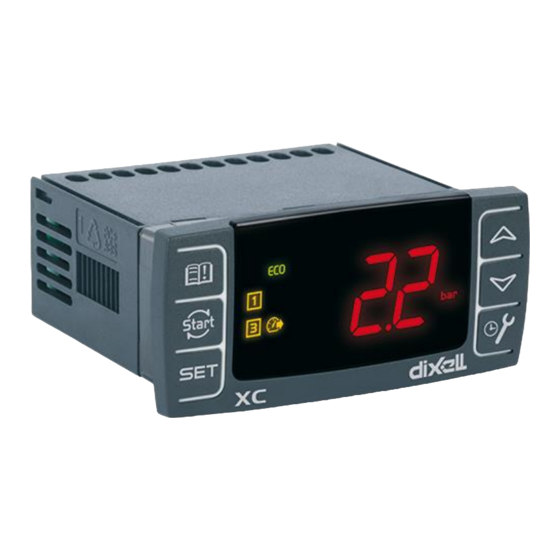
- Page 1 XC15CX XC35CX...
-
Page 2: Table Of Contents
INDEX GENERAL WARNING ........................ 5 PLEASE READ CAREFULLY BEFORE USING THE DEVICE ..............5 SAFETY INSTRUCTIONS ........................5 GENERAL DESCRIPTION ......................5 OPERATIONAL TOOLS ......................6 RATIOMETRIC PRESSURE TRANSDUCERS (0-5VDC) ..............6 PIPE MOUNTING TEMPERATURE PROBE: NP4-67 ................6 MONITORING ADAPTER TOOL: XJ485CX ..................7 WIRING &... - Page 3 12.1 “PR1” MENU ..........................17 12.2 “PR2” MENU ..........................17 12.3 PARAMETER VALUE MODIFICATION ..................18 KEYBOARD LOCK ........................18 HOT-KEY..........................18 14.1 UPLOAD: CONFIGURATION TRANSFER FROM DEVICE TO HOT-KEY ........18 14.2 DOWNLOAD: CONFIGURATION TRANSFER FROM HOT-KEY TO DEVICE .........18 PARAMETERS ........................19 15.1 REGULATION SET-POINT ......................19 15.2...
- Page 4 17.2 ANALOGUE REPEATER ......................33 17.3 “BUMP” FUNCTION........................34 17.4 COMPRESSOR CAPACITY LIMITATION IN CASE OF HIGH CONDENSER PRESSURE/TEMPERATURE ........................34 17.5 PRESSURE PROBE ERROR MANAGEMENT AT START-UP............34 17.6 READING FILTER ........................35 DIGITAL INPUTS........................35 18.1 DIGITAL INPUT DISABLED – ..................35 18.2 REGULATION ENABLED – ...................35 18.3 LOW AND HIGH PRESSURE ALARMS –...
-
Page 5: General Warning
1. GENERAL WARNING 1.1 PLEASE READ CAREFULLY BEFORE USING THE DEVICE This manual is an integral part of the product and should be kept near the instrument for easy and quick reference. The regulator should not be used in applications different from those described below. Moreover, it can not be used as a safety device. -
Page 6: Operational Tools
3. OPERATIONAL TOOLS Description Code Kit for female plug-in terminals @110 or DA000009 60 230VAC Kit for female plug-in terminals @24VAC DA000009 70 TTL to RS485 adapter XJ485CX + CABRS02 Suction Pressure Transducer PPR15 (0T15 bar) Discharge Pressure Transducer PPR30 (0T30 bar) Programming parameter tool HOT KEY 4K 3.1 RATIOMETRIC PRESSURE TRANSDUCERS (0-5VDC) -
Page 7: Monitoring Adapter Tool: Xj485Cx
3.3 MONITORING ADAPTER TOOL: XJ485CX This is a TTL to RS485 physical layer external adapter. It must be inserted on the TTL 5-pin port to convert the TTL output into a 2-wire RS485 output. 4. WIRING & ELECTRICAL CONNECTIONS 4.1 SAFETY INSTRUCTIONS Before connecting cables make sure the power supply complies with the instrument. -
Page 8: Low Voltage Models (24Vac)
4.2.2 Low Voltage Models (24VAC) TRIAC output oA3 is internally connected to the power supply LINE (A1, terminal number 1) Follow instructions on par. 4.3 for probe connections Analogue output oAn can be a PWM (positive on terminal 18) or 0-10Vdc (positive on terminal 17) type. -
Page 9: Digital Inputs
Temperature probes (NTC10k) Pb1 (P1C = NTC): 13-14 Pb2 (P2C =NTC): 13-15 Temperature probes (NTC10k, PT1000, NTC86k) Pb3 (P3C = NTC, PT1000, NTC86k): 19-21 Pb4 (P4C = NTC, PT1000, NTC86k): 19-20 Ratiometric transducers (0.5÷4.5Vdc) Pb1 (P1C = 0-5) 13 (+); 14(in); 16 (gnd) Pb2 (P2C =0-5) 13 (+);... -
Page 10: High Voltage Power Supply Model (110 O 230Vac)
4.6.1 HIGH VOLTAGE POWER SUPPLY MODEL (110 O 230VAC) !!! WARNING: oA3 (TRIAC) OUTPUT is internally connected to the power supply line. DO NOT CONNECT LOW VOLTAGE LOADS !!! Loads: 2 Compressors ON-OFF type 1 Ventilator controlled in phase-cut mode Loads: ... -
Page 11: Low Voltage Power Supply Model (24Vac)
4.6.2 LOW VOLTAGE POWER SUPPLY MODEL (24VAC) !!! WARNING: oA3 (TRIAC) OUTPUT is internally connected to the power supply line. DO NOT CONNECT HIGH VOLTAGE LOADS !!! Loads: 1 Digital Compressor @110 or @230VAC 1 Compressor ON-OFF type ... -
Page 12: Mounting & Installation
Mounting & installation The instruments are suitable only for internal use. Instruments shall be mounted on panel, in a 29x71 mm hole, and fixed using the special brackets supplied. The ambient operating temperature range is between -10T60°C. Avoid locations subject to heavy vibration, corrosive gases or excessive dirt. The same applies to the probes. -
Page 13: User Interface
Enter the “Pr2” programming level by keeping SET+DOWN pressed for 7 sec Select par. Pxi (reading value corresponding to 0.5V) Use SET button and change the lower value by using UP or DOWN buttons Press SET button con confirm and save the new value. After that the PxE (reading value corresponding to 4.5V) will be showed on the display Use SET button and change the higher value by using UP or DOWN buttons Press SET button con confirm and save the new value. -
Page 14: Icons
Manual load restart: if par. r1F=rSt, press this button to restart the loads and previously stopped due to safety alarm ON-OFF: if par. r2F=onF, keep this button pressed for 3 sec to switch ON and OFF the instrument SERVICE / CLOCK: to enter CLOCK and SERVICE menu STORED ALARMS: it gives access to the stored alarms KEY COMBINATION... -
Page 15: Setpoints Modification
DISCHARGE (if enabled): press the SET button once again The display shows the label St2 [Ventilator setpoint] Press the SET button again to show the value of St2 EXIT: Press both SET + UP or wait for 30 sec 8.2 SETPOINTS MODIFICATION Press the SET button for 3 sec The display will show St1 Press the SET button again to show the value of St1 (Compressor setpoint) -
Page 16: Alarm Menu
Number of working hours for output oA1 (thousand of) Number of working hours for output oA1 (unit of) Number of working hours for output oA2 (thousand of) Number of working hours for output oA2 (unit of) Real probe Px value Status of digital input “x”... -
Page 17: Alarm Menu Visualization
Alarm Meaning Low pressure alarm from external sensor (lockout) 11.2 ALARM MENU VISUALIZATION Press the alarm archive (MEM) button Scroll with UP or DOWN button up to label AL0 (first alarm event memorized) Press SET button to enter the event submenu The encoding label relative to the logged event (par. -
Page 18: Parameter Value Modification
SET+DOWN buttons. A parameter placed at the level Pr1 will be indicated by switching on the decimal point toghether with the parameter label. 12.3 PARAMETER VALUE MODIFICATION The following procedure is valid both for Pr1 and Pr2 levels: Access the required programming menu Select the parameter to modify by using UP or DOWN buttons Press the SET button to display the actual parameter value Change the value by using UP or DOWN buttons... -
Page 19: Parameters
Remove the key HOT-KEY NOTE: the "Err" message on the display indicates that the operation is not successful (transfer error). In this case, turn off and then on again the device in order to restart the operation or remove the HOT-KEY to abort the operation. PARAMETERS 15.1 REGULATION SET-POINT SETPOINT 1 for compressor regulation (suction line): LS1 to US1... -
Page 20: Condensing Probe Configuration
End of scaling for pressure transducer P1: (P1i to 99.9 bar; P1i to 999 PSI) it is the pressure value measured from sensor corresponding to 4.5V Pressure transducer P1 calibration: depending on the type of sensor as follow P1C=0-5 -12.0 to 12.0 bar; -200 to 200 PSI ... -
Page 21: Discharge Line Temperature Alarm
Offset for differential HY1: used to move the regulation band above and below St1 P1C=NTC, PT1000 0.0 to 25.5°C; 0 to 45°F P1C=0-5 0.0 to 9.9 bar; 0 to 999 PSI Proportional Integral (PI) time: integration time for PI-regulator that acts on the compressor. -
Page 22: Compressor Safeties
Temperature value for compressor warning: P3, P4=NTC -40 to 110°C; -40 to 230°F P3, P4=NTC86k -40 to 180°C; -40 to 356°F P3, P4=PT1000 -40 to 180°C; -40 to 356°F Differential for DLT alarm deactivation: 0.1 to 25.5°C; 1 to 50°F Delay in DLT alarm activation: 0 to 255 sec Cooling time after detecting a DLT alarm: 0 to 255 min Number of DLT alarms detected before activating the compressor lockout: (0... -
Page 23: Alarms
Differential for phase-cut regulator: 0 to 100% Lower limit for output oA3: input value (FPb) corresponding to the minimum output power (Po1) NTC10k -40 to 110°C; -40 to 230°F NTC86k -40 to 180°C; -40 to 356°F PT1000 -40 to 180°C; -40 to 356°F Ratiometric Pressure probe ... -
Page 24: Dynamic Setpoint
Delay for temperature/pressure alarm activation on condenser: 0 to 255 min Compressor stopped in case of any HAF alarm: n; Y Compressor capacity limitation in case of any HAF alarm: 0 to 80%, if HFL=0 the compressor will be stopped. Delay before stopping the compressor in case of any HAF alarm: 1 to 999 sec Max number HAF alarms before stopping the regulation: (0 to 15) after detecting PnF alarms of the HAF type in an interval of time PiF, the regulation will... -
Page 25: Anti-Resonance
Interval of time with compressor OFF before activating the BUMP function: 0.0 to 23h50min, res. 10 min 15.14 ANTI-RESONANCE Anti-resonance function enabled: n; Y Lower boundary of the first skipped band: If frequency output: 0 to SE1 Hz If voltage output: 0.0 to SE1 V Upper boundary of the first skipped band: If frequency output: SE1 to 500Hz If voltage output: SE1 to 10V... -
Page 26: Digital Inputs
Analogue output: nu=output not used onF=output activated when controller in ON ALr=alarm output EFn=electronic ventilator control PrP=analogue repeater inV=inverter-controlled compressor output Buzzer enabled: n; Y 15.16 DIGITAL INPUTS Digital inputs 1 and 3 depend on the presence of probe P3 and P4 respectively. Digital input 2 is always available. -
Page 27: Regulators
REGULATORS 16.1 DIGITAL COMPRESSOR REGULATION Set par. oA1 and oA3 as below indicated to manage Digital (Scroll or Stream D4D) compressors: oA1=dGt or d4d oA3=dGt or d4d The cooling demand acts on the Digital compressor that, unless of alarms, delays or par. FrC=n, is the first to be activated and the last to be deactivated. -
Page 28: Capacity Decrement And Regulation Stop
NOTE: If the pressure exceeds the [SET+0.5*HY1] value and the Digital compressor is not available (due to the timer delay 2on, 2oF or because of digital input alarm lockout), another compressor will be started (if available). 16.1.2 Capacity decrement and regulation stop When the pressure goes below the value [SET-0.5*HY1] the Digital compressor will be controlled in PWM modulation, at the minimum allowable capacity, for the time toF. -
Page 29: Inverter Controlled Compressor
16.2 INVERTER CONTROLLED COMPRESSOR The management of inverter controlled compressor requires setting the output as follows: oAn=inV oA1=inV Other parameters related to the regulation are described in the following table: Parameter Description Regulation band for St1 Differential HY1: it is used to move the regulation band above and below the St1 value. -
Page 30: How Regulation Works
It is possible to drive inverter with control signal of frequency or voltage (0-10 V DC) type. NOTE: the analog output is not configurable. It may be frequency or voltage type depending on the hardware. 16.2.1 How regulation works The regulation starts when the value of the pressure/temperature of the suction line increases and reaches the St1 value. -
Page 31: Proportional Band Regulation
16.4 PROPORTIONAL BAND REGULATION This kind of regulation is available only for ON-OFF compressors (oA1=CP1 and oA2=CP2) and if par. rtY=Pbr The activation of compressors follows this chart: 16.4.1 COMPRESSOR ROTATION This function is available in case of compressors of equal power and if CPo=SPo. By using this function (par. -
Page 32: Electronic Ventilators
Lto: lower limit Hto: upper limit toH: differential Po1: minimum output value (in percentage) Po2: maximum output value (in percentage) 16.5.3 ELECTRONIC VENTILATORS If par. oAn=EFn, then the analogue output can be used to control electronic ventilators (with input signal command 0-10Vdc). Regulation is proportional in the band defined from par. HY2: When VAL=St2 the analogue output will be forced to Ao1 When St2 <... -
Page 33: Special Functions
During preset intervals of time the maximum allowed speed will be fixed to par. FSS (in percentage). The silent mode will be deactivated as soon as an alarm is detected. SPECIAL FUNCTIONS 17.1 DYNAMIC SET-POINT This function is used to move the condensing regulation band (par. St2 and HY2) and use another (external) temperature (par. -
Page 34: Bump" Function
17.3 “BUMP” FUNCTION This feature is available only using ON-OFF compressors and if par. bMp=Y. When regulation starts, the compressor will be activated and deactivated for a nub number of cycles and with a duration respectively set in par. bon and boF. During the "BUMP" phase pressure/temperature alarms are ignored. -
Page 35: Reading Filter
17.6 READING FILTER It is possible to activate a reading filter which acts on the analogue input values (eg. Pressure/temperature values coming from probes). Following the involved parameters: FiC=mEd, the used value for regulation is the average value calculated on the interval of time tdG FiC=1...100, the used value for regulation is the one calculated by an exponentially weighted moving average filter with coefficients FiC/100. -
Page 36: Permanent Regulation Lock
18.3.2 PERMANENT REGULATION LOCK If during the interval of time defined from the par. diA there is nPx digital input activations, then the permanent lock will be enabled. In this situation: alarm LED and digital output set as alarm (oAx=ALr) will be activated; all the compressor outputs (oA1, oA2) will be deactivated (delayed of 1 sec each from the other);... -
Page 37: Lock Alarm - Ixf=Bal
18.7 LOCK ALARM – ixF=bAL The digital input reports an external alarm conditions which causes the lock of the device. In this case: alarm LED and digital output set as alarm (oAx=ALr) will be activated; all the compressor outputs (oA1, oA2) will be deactivated (delayed of 1 sec each from the other);... -
Page 38: Buzzer Muting And Relay Deactivation
19.1 BUZZER MUTING AND RELAY DEACTIVATION If any alarm condition is active, the buzzer can be muted by pressing any button. Moreover, keeping any button pressed for more than 3 sec will deactivate also the alarm relay. 19.2 TABLE: ALARM CONDITIONS CODE DESCRIPTION DUE TO ACTION RESET... - Page 39 CODE DESCRIPTION DUE TO ACTION RESET Compressor Perform Manual by powering off and on the maintenance maintenance device warning Ventilator Perform Manual by powering off and on the maintenance maintenance device warning EEPROM Contact Dixell Hardware problem memory error Service Set RTC Automatic after error condition configuration...
-
Page 40: Technical Specifications
TECHNICAL SPECIFICATIONS Housing: self-extinguishing ABS Case: frontal 32x74 mm; depth 60mm Mounting: panel mounting in a 71x29mm panel cut-out Protection: IP20; Frontal protection: IP65 Connections: quick connect tabs terminal block 2.5 mm wiring Power supply: according to the model 24VAC, ±10% 110AC 10%, 50/60Hz 230VAC 10%, 50/60Hz...