TEC B-670 SERIES Owner's Manual
Thermal printer
Hide thumbs
Also See for TEC B-670 SERIES:
- Maintenance manual (89 pages) ,
- Owner's manual (155 pages) ,
- Maintenance manual (89 pages)
Table of Contents
Advertisement
Quick Links
Advertisement
Table of Contents

Related Manuals for TEC TEC B-670 SERIES


Summary of Contents for TEC TEC B-670 SERIES
- Page 1 TEC Thermal Printer B-670 SERIES Owner’s Manual Table of Contents...
- Page 2 Do not touch moving parts. To reduce the risk that fingers, jewelry, clothing, etc., be drawn into the moving parts, push the switch in the "OFF" position to stop movement. ® As an NERGY Partner, TOSHIBA TEC has determined that this product meets the NERGY -- Outline of the International The International...
-
Page 3: Safety Summary
Do not attempt to effect repairs or modifications to this equipment. If a fault occurs that cannot be rectified using the procedures described in this manual, turn off the power, unplug the machine, then contact your authorized TOSHIBA TEC representative for assistance. Meanings of Each Symbol This symbol indicates warning items (including cautions). - Page 4 • Utilize our maintenance services. After purchasing the machine, contact your authorized TOSHIBA TEC representative for assistance once a year to have the inside of the machine cleaned. Otherwise, dust will build up inside the machines and may cause a fire or a malfunction. Cleaning is particularly effective before humid rainy seasons.
-
Page 5: Table Of Contents
CAUTION: 1. This manual may not be copied in whole or in part without prior written permission of TOSHIBA TEC. 2. The contents of this manual may be changed without notification. 3. Please refer to your local Authorized Service representative with regard to any queries you may have in this manual. -
Page 6: Applicable Model
1.1 APPLICABLE MODEL B-672-QQ Model name description B - 6 7 2 - Q Q Destination Code QQ : North America bloc Thermal direct/Thermal transfer 1.2 ACCESSORIES Owner's Manual (EM1-33039) Power Cord Print Head Cleaner (24089500013) Media Holder Quality control report... -
Page 7: Specifications
2. SPECIFICATIONS 2. SPECIFICATIONS 2.1 PRINTER Model Item Supply voltage Universal (automatic switching) Be sure to use a power cord which meets the standard. Power consumption 3.5 A, 260 W maximum (standby: 360 mA, 20 W maximum) Operating temperature 5˚C ~ 40˚C range Relative humidity 25% ~ 85%RH (no condensation) -
Page 8: Options
2. SPECIFICATIONS 2.2 OPTION Option Name Type Cutter module B-4208-QM High speed PC B-4800-PC-QM interface kit Strip module B-4908-H-QM D-RAM PC Board FMBC0067801 Flash memory card Description A stop and cut swing cutter This interface kit allows extremely high speed information transfer between the printer and PC. -
Page 9: Media
1. “On the fly issue” means that the printer can draw and print without stopping between labels. 2. To ensure print quality and print head life use only TOSHIBA TEC specified media and ribbons. 3. When using the cutter ensure that label length B plus inter label gap length E exceeds 35 mm. -
Page 10: Overview
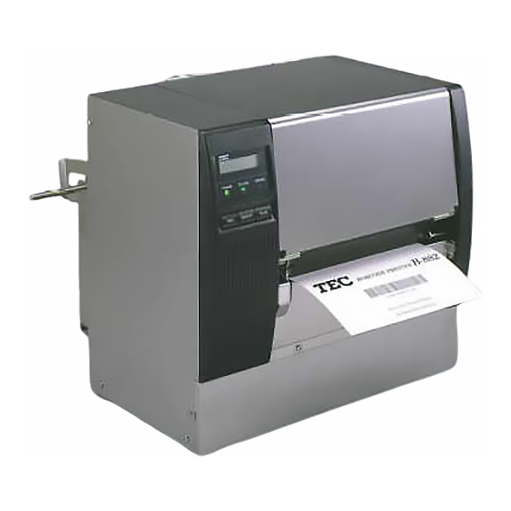
3. OVERVIEW 3. OVERVIEW 3.1 FRONT/REAR VIEW Front View Message Display (LCD) Top Cover Operation Panel Media Outlet 3.2 OPERATION PANEL POWER ON LINE ERROR FEED RESTART PAUSE Fig. 3-2 Memory Card Slot Head Lever Right Side Cover AC Power Inlet Parallel I/F Connector (Centronics) Power Switch... -
Page 11: Dip Switch Functions
4. DIP SWITCH FUNCTIONS 4. DIP SWITCH FUNCTIONS The DIP switches are located to the right of the Guide Wheel. WARNING! Turn the POWER OFF before switching the functions. (1) DIP SW 2 s t i s t i (2) DIP SW 1 a i l NOTES: The Shaded settings are the factory default settings. -
Page 12: Set Up Procedure
5. SET UP PROCEDURE 5. SET UP PROCEDURE 5.1 REQUIREMENTS FOR OPERATION The B-670 has the following requirements: The host computer must have a serial port or centronics parallel port. To communicate with host, either an RS-232C cable or Centronics cable is required. (1) RS-232C cable ... -
Page 13: Installation Procedure
6. INSTALLATION PROCEDURE 6. INSTALLATION PROCEDURE 6.1 CONNECTING THE POWER CORD AND CABLES Turn the POWER SWITCH to OFF before connecting the power cord or cables. Expansion I/O Cable Power Cord Parallel I/F Cable (Centronics) Serial I/F Cable (RS-232C) NOTES: Different cables cannot be used at the same time. -
Page 14: Loading The Ribbon
7. LOADING THE RIBBON 7. LOADING THE RIBBON 1. Do not touch moving parts. To reduce the risk that fingers, jewelry, clothing, etc., be drawn into the moving parts, push the switch in the “OFF” position to stop movement. 2. To avoid injury, be careful not to catch or jam your fingers while opening or closing the cover. - Page 15 7. LOADING THE RIBBON 5. Push the ribbon core against the spring guide wheel, align the protrusion of the guide wheel with the notch of the ribbon core, then set the ribbon. 6. To remove the slack of the ribbon, turn the ribbon core in the direction indicated by the arrow. 7.
-
Page 16: Loading The Media
8. LOADING THE MEDIA 8. LOADING THE MEDIA 1 . Do not touch moving parts. To reduce the risk that fingers, jewelry, clothing, etc., be drawn into the moving parts, push the switch in the “OFF” position to stop movement. 2. - Page 17 The movable sensor can be located anywhere between the left end of the effective print width and the fixed sensor. After changing the sensor type, the sensitivity of the sensor must be adjusted. In this case call a TOSHIBA TEC authorized service representative. firmly. Lock Lever...
- Page 18 8. LOADING THE MEDIA 7. Set the black mark/feed gap sensor to the correct position by turning the adjusting knob. Turning the knob right will move the sensor towards the center of the media while turning left will move it away from the center of the media.
- Page 19 ENGLISH VERSION EO1-33016 8. LOADING THE MEDIA 8. LOADING THE MEDIA 8. The media is now loaded and the sensor position is set. Batch type: Media Fig. 8-6 Cutter type: Where a cutter is fitted load the media as standard and feed it through the cutter module.
- Page 20 8. LOADING THE MEDIA Strip type: Strip labels from the backing paper for about 200-mm long from the top edge of the label roll. Lower the backing paper release bar. Pass the backing paper between the strip roller and the backing paper holder. After taking up any slack of the media, set the backing paper release bar in position.
-
Page 21: Inserting The Optional Flash Memory Card
9. INSERTING THE OPTIONAL FLASH MEMORY CARD 9. INSERTING THE OPTIONAL FLASH MEMORY CARD Turn the power OFF when inserting or removing the flash memory card. CAUTION: To protect memory cards, discharge static electricity from your body by touching the printer rear cover prior to touching the memory cards. -
Page 22: Care/Handling Of The Media And Ribbon
10. CARE/HANDLING OF THE MEDIA AND RIBBON 10. CARE/HANDLING OF THE MEDIA AND RIBBON CAUTION: Be sure to read carefully and understand the Supply Manual. Use only media and ribbon which meet specified requirements. Use of non-specified media and ribbon may shorten the head life and result in problems with bar code readability or print quality. -
Page 23: General Maintenance
11. GENERAL MAINTENANCE 11. GENERAL MAINTENANCE 1. Be cafeful when handling the print head as it becomes very hot. 2. Care must be taken not to injure yourself with the printer paper cutter. 3. Do not touch moving parts. To reduce the risk that fingers, jewelry, clothing, etc., be drawn into the moving parts, push the switch in the “OFF”... - Page 24 11. GENERAL MAINTENANCE 7. Turn the pinch roller lever to the right. 8. Remove the white screw and detach the ribbon end sensor plate. Stud NOTE: When installing the ribbon end sensor plate, be sure to fit both studs in the notches of the ribbon end sensor plate.
-
Page 25: Under The Media Guides
11. GENERAL MAINTENANCE 11.2 UNDER THE MEDIA GUIDES 1. Remove the Media Guides. 2. Remove the jammed Media. 3. Clean “dust and glue” on the Media Guides with a soft cloth moistened with alcohol. 4. Remount the Media guides using the screws. NOTE: Be careful NOT TO LOSE the screw. -
Page 26: Removing Jammed Media
11. GENERAL MAINTENANCE 11.4 REMOVING JAMMED MEDIA 1. Turn the power off. 2. Open the top cover, and right side cover. 3. Turn the head lever to position “OPEN, “ then release the head lock plate. 4. Remove the white screw, unclamp and disconnect the connector of the media guide plate, and then detach the media guide plate. - Page 27 11. GENERAL MAINTENANCE Cleaning the Cutter Unit 1. Be sure to turn the power off before cleaning the cutter unit. 2. The cutters are sharp and care should be taken not to injure yourself when cleaning. 1. Loosen two screws and remove the cutter cover. 2.
-
Page 28: Threshold Setting
11. GENERAL MAINTENANCE 11.5 THRESHOLD SETTING For the printer to maintain a constant print position it uses the transmissive sensor to detect the gap between labels by measuring the amount of light passing through the media. When the media is pre- printed, the darker (or more dense) inks can interfere with this process causing paper jam errors. -
Page 29: Troubleshooting
12. TROUBLESHOOTING 12. TROUBLESHOOTING If you cannot solve a problem with the following solutions, do not attempt to repair it yourself. Turn the power off, unplug the printer, then contact your TOSHIBA TEC representative for assistance. Error Message PAPER JAM 1. - Page 30 12. TROUBLESHOOTING Error Message EXCESS HEAD The print head is too hot. TEMP. HEAD ERROR This message is displayed when sending the head broken check command ([ESC] HD001 [LF] [NUL]) and the print head has a broken element. RIBBON ERROR There is a fault with the ribbon sensor.
- Page 31 12. TROUBLESHOOTING Error Message example) When an error is detected in a command 20 PC001;0A00, bytes of the command are displayed. (ESC, LF, NUL are not displayed.) Command error 0300, 2, 2 Other Error Hardware or software trouble. Message NOTE: If an error is not cleared by pressing the RESTART key, the power must be switched off then on again.
- Page 34 PRINTED IN JAPAN EO1-33016...