Table of Contents
Advertisement
Quick Links
Download this manual
See also:
User Manual
Advertisement
Table of Contents

Related Manuals for TEC B-450-QQ Series


Summary of Contents for TEC B-450-QQ Series
- Page 1 TEC Thermal Printer B-450-QQ SERIES Owner’s Manual Table of Contents...
- Page 2 "Cet appareil numérique de la classe A respecte toutes les exigences du Règlement sur le matériel brouilleur de Canada." (for USA only) (for CANADA only) (for QQ, QQ-PAC only) Copyright © 1999 by TOSHIBA TEC CORPORATION All Rights Reserved 570 Ohito, Ohito-cho, Tagata-gun, Shizuoka-ken, JAPAN...
-
Page 3: Safety Summary
Do not attempt to effect repairs or modifications to this equipment. If a fault occurs that cannot be rectified using the procedures described in this manual, turn off the power, unplug the machine, then contact your authorized TOSHIBA TEC representative for assistance. Meanings of Each Symbol This symbol indicates warning items (including cautions). - Page 4 • Utilize our maintenance services. After purchasing the machine, contact your authorized TOSHIBA TEC representative for assistance once a year to have the inside of the machine cleaned. Otherwise, dust will build up inside the machines and may cause a fire or a malfunction. Cleaning is particularly effective before humid rainy seasons.
-
Page 5: Table Of Contents
APPENDIX ... 13- 1 INDEX CAUTION: 1. This manual may not be copied in whole or in part without prior written permission of TOSHIBA TEC. 2. The contents of this manual may be changed without notification. 3. Please refer to your local Authorized Service representative with regard to any queries you may have in this manual. -
Page 6: Introduction
1. INTRODUCTION 1. INTRODUCTION Thank you for choosing the TEC B-450 Series thermal/transfer printer. This new generation high performance high quality printer is equipped with the latest hardware including the newly developed high density (11.8 dot/mm, 300 dot/inch) print head. This allows very clear print at a maximum speed of 101.6 mm/sec. -
Page 7: Specifications
2. SPECIFICATIONS 2. SPECIFICATIONS 2.1 GENERAL SPECIFICATIONS Model Item Supply voltage 100 ~ 120V, 60Hz Power consumption 0.94 A, 47 W maximum (standby: 0.3 A, 18 W maximum) Operating temperature 5˚C ~ 40˚C Relative humidity 25% ~ 85%RH (no condensation) Dimensions 270 mm (width) x 245 mm (height) x 200 mm (depth), with Supply holder unit 410 mm (depth) -
Page 8: Paper (Label/Tag) Specifications
Outer diameter Ø65 mm (max.) NOTES: 1. To ensure good print quality and maximum print head life use only TOSHIBA TEC specified paper and ribbons. 2. For further information about paper and ribbon, refer to Section 10. CARE/HANDLING OF THE PAPER AND RIBBON. -
Page 9: Appearance
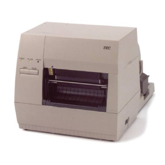
3. APPEARANCE 3. APPEARANCE 3.1 FRONT/REAR VIEW Front View Top Cover Operation Panel Paper Outlet 3.2 OPERATION PANEL Fig. 3-2 Paper Guide Lock Lever Power Switch Supply Holder O : OFF I : ON Fig. 3-1 POWER LED (Green) Lights when the power is turned on. ON-LINE LED (Green) 1) Flashes when communicating with a host computer. -
Page 10: Dip Switch Functions
4. DIP SWITCH FUNCTIONS 4. DIP SWITCH FUNCTIONS The DIP switches are located at the rear of the printer. WARNING! Turn the POWER OFF before changing the DIP switches. DIP SW ON/OFF NOTES: 1. DIP Switch settings are read at power on time. 2. -
Page 11: Setup Procedure
5. SET UP PROCEDURE 5. SET UP PROCEDURE 5.1 REQUIREMENTS FOR OPERATION This machine has the following requirements: The host computer must have a serial port or centronics parallel port. To communicate with host, either an RS-232C cable or Centronics cable is required. (1) RS-232C cable ... -
Page 12: Installation Procedure
6. INSTALLATION PROCEDURE 6. INSTALLATION PROCEDURE 6.1 INSTALLING THE SUPPLY HOLDER UNIT Turn the power OFF before installing the supply holder unit. Fit the two studs on the bottom of the printer into the holes in the supply holder unit. Supply Holder Unit 6.2 CONNECTING THE POWER CORD AND CABLES Turn the POWER SWITCH to OFF before connecting the power cord or cables. -
Page 13: Loading The Ribbon
7. LOADING THE RIBBON 7. LOADING THE RIBBON The printer is capable of printing in both direct thermal and thermal transfer modes. DO NOT LOAD a ribbon when using a direct thermal paper. 1. Turn the power off and open the top cover. 2. - Page 14 7. LOADING THE RIBBON 5. Set the ribbon core (supply side) by fitting the protrusion into the notch. 6. Turn the guide wheel in the arrow-indicating direction to remove any slack of the ribbon. NOTE: Make sure that the ribbon has no wrinkles and the protrusions are fitted into the notches of the ribbon cores.
-
Page 15: Loading The Paper
8. LOADING THE PAPER 8. LOADING THE PAPER This supply holder accepts four sizes of label core: 38 mm, 40 mm, 42 mm and 76.2 mm. When using a paper roll of 38 mm, 40 mm or 42 mm, remove the spacers from the supply holders using the following procedure. - Page 16 8. LOADING THE PAPER 3. Put the paper roll and supply holders on the supply holder unit. NOTE: Paper may be wound outside or inside. Regardless of the paper roll, the paper must be loaded so that the print side faces upward. Paper wound inside.
- Page 17 8. LOADING THE PAPER NOTE: Pass the paper straight from the supply holder to paper outlet. Failure to do this may cause skew feeding or paper jam. A = B 8. Close the top cover. Paper loading is now completed. Batch type: Cutter type: Where a cutter is fitted load the paper as standard and feed it through the cutter module.
- Page 18 8. LOADING THE PAPER EO1-33006 8. LOADING THE PAPER Strip type: 1 Strip the labels from the backing paper for about 200-mm long from the top edge of the label roll. 2 First push the strip lever toward the printer to release the hook, and then pull the strip lever. 3 Pass the backing paper between the strip roller and the strip guide roller.
-
Page 19: Threshold Setting
9. THRESHOLD SETTING 9. THRESHOLD SETTING For the printer to maintain a constant print position it uses the transmissive sensor to measure the amount of light passing through the gap between labels. When the paper is pre-printed, the darker (or more dense) inks can interfere with this process causing paper jam errors. -
Page 20: Care/Handling Of The Paper And Ribbon
10. CARE/HANDLING OF THE PAPER AND RIBBON CAUTION: Be sure to read carefully and understand the Supply Manual. Ask your nearest authorized TOSHIBA TEC representative for the Supply Manual. Use only paper and ribbon which meet specified requirements. Use of non-specified paper and ribbon may shorten the head life and result in problems with bar code readability or print quality. -
Page 21: General Maintenance
3. Turn the head lever to raise the print head. 4. Remove the ribbon and paper. 5. Clean the print head element with print head cleaner NOTE: Please purchase the print head cleaner from the authorized TOSHIBA TEC service representative. Print Head Cleaner (24089500013) -
Page 22: Covers
11. GENERAL MAINTENANCE 6. Clean the platen with a cloth moistened with alcohol. 7. Remove any dust or glue from the detection area of the sensors and paper path with a soft cloth. Platen 8. Remove the supply holder rollers from the supply holder unit. Remove any dust from the recessed portions of the base and wipe glues from the rollers with a slightly moistened soft cloth. -
Page 23: Removing Jammed Paper
11. GENERAL MAINTENANCE 11.3 REMOVING JAMMED PAPER 1. Turn the power off. 2. Open the top cover. 3. Move the head release lever toward the front of the printer to raise the print head block. 4. Remove the ribbon and paper. 5. - Page 24 11. GENERAL MAINTENANCE 2. Fit the enclosed Allen Key into the right side of the cutter unit to rotate the cutter manually. Remove the jammed paper and any paper particles from the cutter. 3. Clean the cutter with dry cloth. Cutter 4.
-
Page 25: Troubleshooting
If you cannot solve a problem with the following solutions, do not attempt to repair it yourself. Turn the power off, unplug the printer, then contact your TOSHIBA TEC representative for assistance. If the error lamp lights during printing, refer to the following troubleshooting to solve the problem. - Page 26 12. TROUBLESHOOTING Error type CUTTER ERROR Paper is jammed in the cutter. Other Error Hardware or software trouble. NOTE: If an error cannot be cleared by pressing the [PAUSE] key, the power must be switched off then on again. Once the power has been switched off and on, all the print data in the printer is cleared. Problem No print.
-
Page 27: Appendix
APPENDIX APPENDIX ASCII Code Chart Font Sample Barcode Sample 13-1 EO1-33006 APPENDIX... -
Page 28: Index
INDEX AC Power inlet ... 3-1 Auto media feed ... 4-1 Bar code types ... 2-1 Cleaning ... 11-1 DIP switch ... 3-1, 4-1 Fonts ... 2-1 Interface ... 1-1, 2-1 Centronics cable ... 5-1 Parallel interface ... 2-1 RS-232C cable description ... 5-1 Serial interface ... - Page 30 PRINTED IN JAPAN EO1-33006...