
Related Manuals for Culligan CSM Series


Summary of Contents for Culligan CSM Series
- Page 1 Cat. No. 01016370 Rev. F 02/24/14 DCO # 014223 Installation, Operating and Service Instructions CULLIGAN CSM SERIES ® WATER SOFTENER ©2014 Culligan International Com pa ny Printed in USA...
- Page 2 Products manufactured and marketed by Culligan International Company (Culligan) and its affiliates are protected by patents issued or pending in the United States and other countries. Culligan reserves the right to change the specifications referred to in this literature at any time without prior notice. Culligan, Aqua-Sensor, Tripl-Hull, and SoftMinder are trademarks of Culligan International Company or its affiliates.
-
Page 3: Table Of Contents
Installation, Operating and Service Instructions CULLIGAN CSM SERIES ® WATER SOFTENER Contents Introduction ................ Operation Log ..............Performance Specifications ..........Basic Principles ..............Flow Diagrams..............Controller Features ............Operation ................. Installation ............... Schematic ................ Programming ..............Final Start-up ..............Suggested Preventative Maintenance ...... - Page 4 This page intentionally left blank. Cat. No. 01016370 Culligan® CSM Series Softeners...
-
Page 5: Introduction
Introduction Read this Manual First Before you operate the Culligan CSM Water Softener, read this manual to become familiar with the device and its capabilities. The Culligan CSM Water Softeners are tested and certified by WQA against NSF/ANSI 372 for low lead requirement. -
Page 6: Performance Specifications
Performance Specifications Culligan commercial water softeners are designed to remove hardness minerals from water. In order to function properly, some operational parameters must be followed. They include: • An operating pressure of water or air between 30 and 100 psi. If pressure is greater, a pressure regulating valve should be installed ahead of the system. - Page 7 Table 2. CSM Softener Dimensions Model Resin Tank Size - Brinemaker Valve Size (in.) *Minimum System LxWxH Dimensions (in.) CSM Single CSM Duplex CSM Triplex 150-2 20x54-24x48 20x54-24x48 20x54-24x48 56x30x74 88x30x74 120x30x74 210-2 24x54-24x48 24x54-24x48 24x54-24x48 60x34x76 96x34x76 132x34x76 300-2 30x60-30x48 30x60-30x48 30x60-30x48...
-
Page 8: Basic Principles
HOW DO YOU CONTROL THE REGENERATION PROCESS? The regeneration process for your commercial water softener is controlled automatically either on a predetermined time, volume, or external signal basis through the use of the Culligan MVP controller with optional AquaSensor ®... -
Page 9: Flow Diagrams
Flow Diagrams Flow Diagram - Service Step (Home Position) These diagrams illustrate the simplicity of the Brunermatic valve and positive control of flow direction. Note that only diaphragm valves 1 & 4 are open and flow is directed to top of resin tank, through resin bed, out bottom of tank into service line. - Page 10 * Single tank systems only BACKWASH Injector Pilot Strainer Soft Water Hard Water Hard Brine Water Inlet *Hard Water By-pass to Service Flow Control Resin To Drain Sample Cock Position Supporting Bed Dial Figure 2. Backwash Cat. No. 01016370 Culligan® CSM Series Softeners...
- Page 11 Flow Diagram - Brine Draw Step (Position 2) Diaphragm valve #6 opens. Note that only two valves are open in this cycle (No. 6 and No. 17*). Pressure directed through pilot valve holds other valves closed. Flow through brine injector creates vacuum and draws brine. Note brining assembly detail showing valve in open position.
- Page 12 SLOW RINSE Injector Pilot Strainer Soft Water Hard Water Hard Brine Water Inlet *Hard Water By-pass to Service Flow Control Resin To Drain Sample Cock Position Supporting Bed Dial Figure 4. Slow Rinse Cat. No. 01016370 Culligan® CSM Series Softeners...
- Page 13 Flow Diagram - Flush Step (Position 3) Diaphragm valves 1, 6 and 17* are open. Increased flow is directed to top of resin tank, down through bed, and out to drain. Settles and packs resin bed. Purges resin tank of hard water. nsures that all brine has been rinsed out.
-
Page 14: Controller Features
Controller Features The Culligan MVP control’s primary function is to initiate and control the regen- eration process via methods that are most convenient and cost effective for the customer while offering many operation features and benefits. Features Power Source Electrical power required for the control is 24-Volt 50/60 Hz AC current. A plug-in... - Page 15 Segmented Brine Draw/Rinse Cycle - Brine Reclaim Capability This is a feature of the Culligan MVP controller program which allows the user to configure the system for brine reclaim with a minimum of additional valves and/or other types of hardware.
-
Page 16: Operation
The Aqua-Sensor detects when the resin bed has reached its point of exhaustion and, as a result, initiate a regeneration sequence. This is the most cost-effective method of operation and may be combined with any of the operational modes previously described. Cat. No. 01016370 Culligan® CSM Series Softeners... -
Page 17: Installation
Installation Suggested Piping Installations MANUAL BYPASS VALVE MANUAL BYPASS VALVE FLOW METER (NORMALLY CLOSED) (NORMALLY CLOSED) INLET WATER SOFT WATER HARD WATER SOFT WATER MANUAL OUTLET ISOLATION VALVE MANUAL INLET MANUAL OUTLET MANUAL INLET ISOLATION VALVE ISOLATION VALVE ISOLATION VALVE FLOW METER CONTROLLER CONTROLLER... - Page 18 Check inside the tank to make sure that all of the laterals are tight. (Figure 10) CAUTION! Do Not Proceed if any laterals are broken. Consult Culligan for assistance. If any are loose, hand tighten only. Do not use a wrench.
- Page 19 Timed Brine Refill Valve Installation The timed brine, refill valve, (accessory kit 01019576) contains one refill valve assembly and a selection of timed refill flow control washers. To determine which washer is to be used, select the washer as indicated in the table below and install it in the position shown in Figure 12.
- Page 20 Table 16 on page 94 for sizing parameters. Position the salt storage tank in a convenient location on a smooth surface. Brine chamber Connect 3/4” pipe to valve. Overflow Brine Valve Figure 14. Cat. No. 01016370 Culligan® CSM Series Softeners...
- Page 21 Therefore your system may not utilize this portion of the manual. Two popular types of flow measuring devices can be used with the controller; paddlewheel flow sensors or the Culligan in-line turbine meter. Please refer to the following chart for the number of meters required for your system configuration.
- Page 22 = 10” 20 x D 5 x D 5 x D 50 x D Figure 18. Example: D = 2” Single Elbow Prior to Flow Sensor Valve Prior to Flow Sensor Figure 16. Cat. No. 01016370 Culligan® CSM Series Softeners...
- Page 23 Position of the Flow Sensor Package The flow sensor position is also important to the accuracy of the output signal. When installing the flow sensor in a horizontal pipe, the optimum position of the flow sensor in the pipe is at 0 or 180 degrees, assuming the pipe is always full of liquid and contains no suspended solids.
- Page 24 If mounted vertically, the water flow must be upward. Turbine meters however must be supported as required by local plumbing codes; typically 18” before and after each joint (in a horizontal run of pipe). Figure 24. Figure 25. Cat. No. 01016370 Culligan® CSM Series Softeners...
- Page 25 Installing the Gravel Support Bed Verify that the correct type and amount of gravel for the system is on site. The proper amount of gravel is indicated on the following table. If the correct type and amount of gravel is not on site, DO NOT load the tank. Contact the equipment provider for assistance.
- Page 26 DO NOT leave more cable than necessary inside the tank. Any excess cable should be coiled near the controller, outside of the resin tank. Figure 30. Cat. No. 01016370 Culligan® CSM Series Softeners...
- Page 27 Installing Resin Before adding the resin, verify that the correct type and amount of resin for the softener you are installing is on site. Again, refer to the table on the pre- vious page for the correct resin quantity. If the correct type and amount of resin is not on site, contact the equipment provider.
- Page 28 CAUTION! The port numbers on the Brunermatic valve may not coincide with the ports on the MVP pilot valve. Refer to the port numbering chart for cross-reference information. Table 7. Cross Reference Port Chart Pilot Valve Brunermatic Valve Brunermatic Valve Figure 35. Cat. No. 01016370 Culligan® CSM Series Softeners...
- Page 29 Brunermatic Valve Figure 36. PARALLEL (Non-Progressive Flow) SYSTEM W/PLUGGED BYPASS Cat. No. 01016370 Installation...
- Page 30 From solenoid valve port number 3 to port number 2 on the pilot valve body. The detailed tubing schematic is shown below (Figure 37). • Wiring is detailed on page Figure 37. Solenoid Valve Kit Brunermatic Valve Figure 38. ALTERNATING/PROGRESSIVE FLOW PARALLEL SYSTEM W/PLUGGED BYPASS Cat. No. 01016370 Culligan® CSM Series Softeners...
- Page 31 Sequence of Operation When a softener is in standby or a regeneration cycle, the MVP controller sends a signal to the P7 SOL-VIV terminal of the primary circuit board, activating the solenoid valve. The orange LED will be on at this time. When the solenoid valve is electrically activated, ports #1 and #2 of the solenoid (Figure 39) become common.
- Page 32 Using a small screwdriver, loosen all the terminal strip binding screws on the main circuit board that do not con- tain wires by turning counterclockwise until the wire clamp has been fully opened (see Figure 41). Figure 40. Figure 41. Cat. No. 01016370 Culligan® CSM Series Softeners...
- Page 33 Cable Routing All input and output connections to the circuit board are 24 volt or less. Non-shielded type cable is provided for installation. It is imperative that the correct type of cable is used to reduce the possibility of radiated electrical noise from entering the wiring.
-
Page 34: Schematic
Do not connect the P3 communication cable to the P12 circuit board connection. Doing so will damage the circuit board. CAUTION! Connecting 24V to the 2.5VAC connection on the circuit board will damage the circuit board. Figure 43. Cat. No. 01016370 Culligan® CSM Series Softeners... - Page 35 24V TRANSFORMER The MVP control is powered by a 24V/50VA transformer. If there are multiple controls in the system being installed, each control will require its own transformer. It is recommended that the transformer be plugged into a dedicated 120V circuit. CAUTION! Connecting 24V to the 2.5V connection on the circuit board will damage the circuit board Connect one of the wires from the 24V cable to one of the outermost 24V transformer screw terminals...
- Page 36 The wires can be trimmed to a suitable length. Figure 46. Figure 47. CIRCUIT BOARD P9 Power 2.5VAC 24VAC Aux1 Aux2 Aqua Flow Meter Snsr WHITE REFILL SOLENOID VALVE BLACK TRIM OFF GREEN WIRE Figure 48. Cat. No. 01016370 Culligan® CSM Series Softeners...
- Page 37 Communication Cable and Blocking Solenoids - Multiple Units NOTE Disregard this information and proceed to flow sensor schematic (optional) information when install- ing single tank configurations. CAUTION! Do not connect P3 communication cable to P12 circuit board connection. Doing so will damage the circuit board.
- Page 38 On twin alternating systems, part number 01016369 duplex installation kit will be required. This kit con- tains: • One (1) interconnect cable with end connec- tors. • Two (2) solenoid valves with tubing and fittings. Figure 52. Cat. No. 01016370 Culligan® CSM Series Softeners...
- Page 39 Flow Sensor Meter Schematic (optional) The MVP controller is capable of detecting the signal from a Hall effect sensor device to provide flow rate information, totalization and volume based regeneration initiation. The flow meter device is automatically detected when connected to the controller.
- Page 40 Power to circuit board 24V Power to circuit board 2.5VAC only required for Aqua-Sensor installations Figure 55. CAUTION! Connecting 24V to the 2.5V connection on the circuit board will damage the circuit board. Figure 54. Cat. No. 01016370 Culligan® CSM Series Softeners...
- Page 41 Auxiliary Output #1 & #2 (Optional) The Auxiliary Output #1 & #2 (P5 Aux 1 & P8 Aux 2 - reference Figure 56) are output triacs that can be programmed to provide power to a “normally open” (normally no power to auxiliary output until power required) or a “normally closed” contact (user choice).
- Page 42 LOCKOUT Flow Aqua SOLENOID Meter Snsr OUTPUT P9 Power 2.5VAC 24VAC Aux1 Aux2 Flow Aqua Meter Snsr POLE EXTERNAL SOURCE POLE Regen Signal 24V DPDT RELAY DUPLEX ALTERNATING WITH EXTERNAL SOURCE Figure 58. Cat. No. 01016370 Culligan® CSM Series Softeners...
-
Page 43: Programming
DIP Switches The Culligan MVP controller uses a series of ten (10) DIP Switches to streamline the programming process. Figure 59 shows the DIP Switch strip placement on the circuit board and the abbreviated text indicating the function of each switch. - Page 44 Slow Rinse (10 minute default time); BR3 - Slow Rinse (10 minute default time). Once the DIP switches have been properly selected for each controller, power may be applied and programming of the control(s) continued. Cat. No. 01016370 Culligan® CSM Series Softeners...
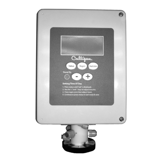
- Page 45 Programming - Key Pad Familiarization Once the DIP switch settings have been established the Culligan MVP control is ready to accept user input. User input is done through the keypad on the front of the MVP circuit board. Refer to Figure 60 for a description of the layout of the keypad.
- Page 46 Press the Statistics key once and then press “-” until “Unit 1 MASTER” is displayed. Press and hold the Regeneration key for (3) seconds. The unit will home and the ID# will have been success- fully erased. Cat. No. 01016370 Culligan® CSM Series Softeners...
- Page 47 10% reserve capacity. The purpose of the reserve capacity in multiple tank systems is to allow for subtle changes in water chemistry. Determining Batch Set Point To determine the batch set point for programming the Culligan MVP controller, use the following formula: Total Capacity - Reserve Capacity Gallons =...
- Page 48 Program Data Input There are a couple of items to note that can make the programming the Culligan MVP control a little easier. They are: Slew Rates This term refers to the speed at which the display moves through the input of mate- rial.
- Page 49 Auxiliary Input Delay* - (All modes) “AUX IN” (Figure 66) programming is required only if the AUX In terminal is being used. This establishes the uninterrupted period of time (in sec- onds) that a signal must be received through the auxiliary input before the controller is to react by initiating a regeneration sequence.
- Page 50 To advance to the next day in the program sequence, use the Regeneration key and repeat the steps from the previous Figure 78. paragraph for each day of the week. When complete, press the Status key once to advance to the next step. Cat. No. 01016370 Culligan® CSM Series Softeners...
- Page 51 Current Day of the Week* - If any of the days from step 9A. were set to “Y”, the display will show “SetdAY” (Figure 79) fol- lowed by “SUN” (Figure 80). Use the “+” or “-” keys to scroll the display to the current day of the week.
- Page 52 (adjustable from 1 to 99). The minutes setting indicates the period Closed, active in Home cycle for 10 of time, in minutes, that the AUX 1 output triac is powered for “NO” (Nor- minutes. Cat. No. 01016370 Culligan® CSM Series Softeners...
- Page 53 mally Open) or inactive for “NC” (Normally Closed). Press the REGEN key to revert back to the contact status programming or the STATUS key to save the setting and move on to the next programming step. When powered, the AUX 1 icon shall be lit in the display. Example Of Aux 1 Use - Set the program to “NO 3 15”...
- Page 54 (1-17) that apply to your system. If enabled, you will be prompted to update all other controls upon reaching step 17. Once all programming has been completed, the system is ready to provide treated water. Figure 95. Figure 94. Cat. No. 01016370 Culligan® CSM Series Softeners...
- Page 55 Program Log Use this section to record the program settings for this system. It is also suggested that additional copies be made and kept on file near the installation and with the local Culligan dealer. Program Date: Installer: Site Location:...
- Page 56 Pressing the “+” key from the Statistics menu will move the display back to the current diagnostic cycle. The “+” key will be ignored once the control returns to the H or home posi- tion. Figure 100. Figure 101. Cat. No. 01016370 Culligan® CSM Series Softeners...
- Page 57 Culligan MVP Control Statistic Functions The Culligan MVP control has the ability to provide statistical information about the system. This data is accessed through the Statistics key. To move through the statistical data available, use the “-” key. Each push of the “-” key will display new information. The follow- ing table briefly defines the data available while in this mode.
-
Page 58: Final Start-Up
Manually rotate the position dial to the #1 position. Backwash the media for 10 minutes or until the drain water is clear. After the backwash is complete, manually rotate the position dial back to the H (Home) position. Cat. No. 01016370 Culligan® CSM Series Softeners... - Page 59 Installation Wrap Up Fill the Salt Storage Container Before filling the brine tank with salt, refer to Appendix "Table 15. CSM Refill Minutes/Salt Dosage/Capacity" on page to find the salt dosage/capacity rating per regeneration Dry storage If the salt dosage/capacity rating falls within the non-shaded area, fill the storage container to within a few inches of the top.
- Page 60 Clean up the unit and the installation site, removing any soldering or pipe threading residues from the equipment with a damp towel. For units with steel tanks, place the Culligan label (packed with the media tank) on the front of the tank. Explain the operation of the system and the Suggested Preventative Maintenance Inspection Schedule (page 58) to the customer.
-
Page 61: Suggested Preventative Maintenance
HAZARD FROM TOXIC FUMES! CHLORINE BLEACH AND COMMON IRON CONTROL CHEMICALS MAY GENERATE TOXIC FUMES WHEN MIXED. • IF THE UNIT USES CULLIGAN SOFNER-GARD® OR OTHER COMPOUNDS CON- TAINING SODIUM HYDROSULFITE, SODIUM BISULFITE, OR ANY OTHER REDUC- ING AGENT, DISCONNECT THE DEVICE FEEDING THE CHEMICAL(S) AND MANU- ALLY REGENERATE THE UNIT BEFORE SANITIZING. - Page 62 The Operation & Performance Specifications (page 2 of this manual) provides the limits of water characteristics for the CSM Series water softeners. If the water characteristics fall outside these limits, additional water treatment equipment may be required, or the water characteristics should be brought inside the limits.
- Page 63 Culligan MVP Control Test Functions The Culligan MVP control has a diagnostic feature that allows the user to verify the operation of the board components. Moving DIP switch 1 from “R” (Run) to “T” (Test) or the ON position enters the test mode. (See...
- Page 64 Display to blink x10 icon when meter is sending pulses Spin Flow Meter Aqua-Sensor Display to show “REGEN” icon when Aqua-Sensor is connected & Connect & Balance Aqua-Sensor balanced Display to blink “REGEN” icon when unbalanced signal received Unbalance Aqua-Sensor Cat. No. 01016370 Culligan® CSM Series Softeners...
- Page 65 Troubleshooting Guide PROBLEM OR SYMPTOM CHECK PROCEDURE CAUSE Slight Leak to Drain Disconnect pilot valve tubing at back- Flow from tubing indicates leaky seal wash control. in pilot valve spool. If pilot valve is not leaking, use a test Possible ruptured diaphragm. If wa- kit and check for hard water at the ter tests soft then valve #6 is open.
- Page 66 Eliminate source or install air vent in top of tank. Leak From End of Pilot Body Visually inspect u-cup and seals on Worn or pinched u-cup or a scratch on pilot valve spool. the pilot valve spool. Cat. No. 01016370 Culligan® CSM Series Softeners...
- Page 67 PROBLEM OR SYMPTOM CHECK PROCEDURE CAUSE Pilot Does Not Pressurize or Vent Check Screen on Pilot Strainer Clogged Screen prevents control Valve Ports Properly pressure from reaching pilot valve (and solenoid valves if applicable). Manually rotate the pilot (in the If water flows out of the control tubing, proper direction) as required until check the fitting in the valve port cover...
- Page 68 You may also power down the control for 60 seconds or toggle a DIP switch. If the problem is still present after at- tempting to clear the error code, the code will remain in the display. Cat. No. 01016370 Culligan® CSM Series Softeners Diagnostics...
-
Page 69: Service
Service Procedure for Depressurizing the Brunermatic Valve and System for Service Complete shut down procedure is as follows: Disconnect the electrical power to the MVP controller. Make certain that the lines you shut off are for the system you are performing service on. Open by-pass valve if one is available. - Page 70 Evidence of the old numbering scheme is noted by the use of port number 17 on the pilot valve and/or Brunermatic valve. If the numbering scheme of the pilot valve does not completely match the Brunermatic valve, the following chart should be referred to for conversion purposes. Cat. No. 01016370 Culligan® CSM Series Softeners...
- Page 71 Backwash Flow Controllers - Theory of Operation and Service Located on the drain connection of the Brunermatic valve, the purpose of the backwash flow controller is to regulate the up flow backwash required to expand and agitate the resin in the softener. The softener will allow maximum expansion of the resin, while preventing any loss to the drain.
- Page 72 Connect the flexible tubing to the compression fitting located in the side of the Backwash Flow Control nipple. Insert and tighten clean-out plug. (Figure 108) Figure 109. Figure 110. Figure 111. Figure 112. Cat. No. 01016370 Culligan® CSM Series Softeners...
- Page 73 Aqua-Sensor Probe Resin Test The Probe Resin Test uses fully regenerated, but previously used, Cullex® resin to simulate a balanced environment. Run this test only on a circuit board that has passed the Circuit Board Test with simulator device. Preparation You will need a container that can hold enough regenerated Cullex resin to completely immerse the probe’s electrodes without making contact with the container’s sidewall.
- Page 74 Test circuit board nozzle and screen & probe for plugging or fouling Check Resin function. Short salting could cause reduced capacity Test circuit board & probe Check pistons for internal leak Figure 113. Cat. No. 01016370 Culligan® CSM Series Softeners...
- Page 75 Pilot Valve Spool Removal & Replacement Close the manual inlet isolation valve, the manual outlet isolation valve, the manual brine valve, and any exter- nal source of pressure to the pilot valve assembly. Follow the instructions on page 65 for depressurizing the system before proceeding.
- Page 76 Reinstall the pilot valve body assembly in the enclosure. Make certain the pilot valve position faces left when viewed from the front of the controller. Reconnect the four quick connect wire leads to the microswitches. Connect the two motor leads to the circuit board. Reconnect all pilot valve tube connections. Cat. No. 01016370 Culligan® CSM Series Softeners...
- Page 77 Pilot Valve Assembly Replacement NOTE The cam gear is designed to only be installed one way onto the pilot valve spool. The flat portion of the pilot valve spool must align with the flat side of the cam gear’s pilot receptacle. When properly positioned, the cam will snap into place on the pilot valve spool.
-
Page 78: Service Parts
Service Parts CSM Series Softener Parts List The following section includes all available replacement parts for the CSM product line. This list is divided into the following sections: Section 1 - Replacement Resin Tank and Supporting Parts. Section 2 - Brunermatic Multiport Valve 2”... - Page 79 Section 1 #1-4 Replacement Resin Tank and Support Parts Standard Replacement Tank Assembly* #1-3 Tanks 20-30” are supplied with a hand-hole in the top and lower sideshell. Tanks 36” diameter and larger are supplied with a manhole in the top and a hand-hole in the side.
- Page 80 11 x 15 ASME Tanks Side 00440783 6 x 8 Handhole Cover Lined No Hole 00440780 6 x 8 Gasket 00440779 6 x 8 Yoke 00770072 6 x 8 Bolt w/Nut 3/4-10 x 3-1/2” Cat. No. 01016370 Culligan® CSM Series Softeners...
- Page 81 Item # 1-5 Internals Model Tank Size/ Laterals- Nipple - Lower Bushing Inlet Pipe Upper Valve Size Item 1 NC/ASME Item 4 Item 5 Elbow Item 2 Item 3 Item 6 150-2 20x54-2” 01020100 01020032-8 A1696004 01020360 00X10836 210-2 24x54-2” 01020100 01020033-8 A1696004...
- Page 82 The Brunermatic® D-180 Multiport Valve assemblies that are covered in this section are listed below. All valve assem- blies listed are for cold water application only. VALVE PART NO. THREAD SIZE TYPE OF THREAD 01017241 2” Figure 119. 2” Valve Assembly Cat. No. 01016370 Culligan® CSM Series Softeners...
- Page 83 Replacement Parts and Repair Kits - 2” Brunermatic® D-180 Multiport Valve Assembly COMBINATION REPLACEMENT REPLACEMENT QTY. NEEDED ITEM DESCRIPTION QTY. QTY. VALVE PART NO. PART NO. PKG. PKG. 2” Brunermatic Valve Assembly Injector As- 01017241 sembly or Pilot Strainer Assembly without Pilot Strainer Assembly, Universal A1013390 Soft Water Sample Cock...
- Page 84 The Brunermatic® D-180 Multiport Valve assemblies that are covered in this section are listed below. All valve assem- blies listed are for cold water application only. VALVE PART NO. THREAD SIZE TYPE OF THREAD 01017242 3” Figure 120. 3” Valve Assembly Cat. No. 01016370 Culligan® CSM Series Softeners...
- Page 85 Replacement Parts and Repair Kits - 3” Brunermatic® D-180 Multiport Valve Assembly COMBINATION REPLACEMENT REPLACEMENT QTY. NEEDED ITEM DESCRIPTION QTY. QTY. VALVE PART NO. PART NO. PKG. PKG. 3” Brunermatic Valve Assembly without Injector 01017242 Assembly or Pilot Strainer Assembly Pilot Strainer Assembly, Universal A1013390 Soft Water Sample Cock...
- Page 86 A1013418 900-2” 42 X 60-2” 01017395 10.0 A1013426 A1013408 A1013418 900-3” 42 X 60-3” 01017395 10.0 A1013426 A1013408 A1013418 *See next page for included parts quantities and descriptions. Figure 121. 1” Injector Assembly Cat. No. 01016370 Culligan® CSM Series Softeners...
- Page 87 Replacement Parts and Repair Kits - B544 Injector Assembly 1” COMBINATION REPLACEMENT REPLACEMENT QTY. NEEDED ITEM DESCRIPTION QTY. QTY. VALVE PART NO. PART NO. PKG. PKG. Plug 1-1/2” End Cap 01012803 Kit, Throat Assembly. Includes Throat and O-Ring. Previous Contains 2 each of 6 throat sizes and 12 Page O-Rings.
- Page 88 Model Flow Controller Part # Backwash Rate (gpm) 150-2 A1451014 210-2” A1127002 13.5 300-2” A1127004 300-3” A1127004 450-2” A1127004 450-3” A1127004 600-2” A1127006 600-3” A1127006 750-2” A1128020 750-3” A1128020 900-2” A1128020 900-3” A1128020 Cat. No. 01016370 Culligan® CSM Series Softeners...
- Page 89 Section 5 Brine Refill Valve Item # Part # Description Unit 01019576 MVP™ Softener Kit - Includes brine refill valve, coil, connector & fittings 01003059 Brine Refill Valve - Replacement - Includes 1-16, 28 01020714 Kit Refill Valve internals, incl items 2 to 6 & 9 to 16 BODY VALVE BRINE REFILL IMPREG, SCREEN REFILL BODY , VALVE, CHECK, BRINE REFILL VALVE...
- Page 90 Cat. No. 01016370 Culligan® CSM Series Softeners...
- Page 91 Section 6 Yellow Wire (WIRE HARNESS ONLY) Brown Wire Brown Wire Yellow Wire Red Wire Cat. No. 01016370 Service Parts...
- Page 92 Culligan MVP Valve Mounted Controller Item # Qty. Needed Description Replacement Kit Per Controller Part # Qty. Per Package – Controller - Complete (Does not include items 11 or 12) 01016170 Gasket, Time Fill 00772964 Circuit Board 01016367 Pilot Drive Assembly...
- Page 93 Section 7 24”, 30”, 39” and 42” Brine Systems Item No. Part No. Description Qty Req. 01024800 24” x 50” Brine System Complete 01024801 30” x 50” Brine System Complete 01024802 39” x 48” Brine System Complete 01024803 42” x 48” Brine System Complete Tank Cover 01019623...
- Page 94 ROD ASSEMBLY FLOAT ASSEMBLY VIEW SEE SECTION 1 25 SCALE 0.500 DETAIL A-A 8-14 IN-LBS (2 PLACES) TORQUE TYP. (4) PLACES 31.00 (REF.) 10.75 WITH FLOAT (REF.) ROD IN SEATED 14.87 POSITION (REF.) Cat. No. 01016370 Culligan® CSM Series Softeners...
- Page 95 Item # Part # Description Unit 01019627 Brine Valve, Repl, 24”-42” systems w/elbow 01020618 Brine Valve Repair Kit - includes items below listed w/”B” BASE ASSEMBLY, 3/4” BRINE GASKET CAP,BRINE VALVE SCREW,#6X3/4,PHILLIPS PAN HD NUT,10-32,HEX,18-8SS COUPLING,3/4”,TXT,PVC SCH.80 PIPE PVC 0.75”NPTX46.750”SCH80 WASHER, #10, TYPE B, SERIES N SCREW,MACH,#10-32x1-5/8,18-8SS,HEX HD SLT NUT,1/4-20,HEX,18-8SS...
-
Page 96: Appendix A System Data
*The suggested Progressive Flow Trip Point is simply a suggested flow rate at which point an additional tank will be brought on-line if facility flow demands meet this rate. The Culligan MVP Controller will not remove tank brought on-line by attaining the Trip Point unless the flow is <95% of the Trip Point amount for a 60 second period. In the event additional units are not brought on-line or off-line when desired, simply adjust the programmed Trip Point. - Page 97 Table 15. CSM Refill Minutes/Salt Dosage/Capacity Resin Vol Refill Flow Washer Size (GPM) Resin Tank Dia (in.) Refill Min lbs/ Dos- Capac- lbs/ Dos- Capac- lbs/ Dos- Capacity lbs/ Dos- Capacity lbs/ Dos- Capacity lbs/ Dos- Capacity lbs/ Dos- Capacity ft∆...
- Page 98 2400 16.0 1.10 3.80 1554 6.40 1800 15.00 2400 20.0 1.90 4.90 1677 1.60 1183 4.10 1217 8.10 2400 16.0 2.90 1430 2.62 1069 5.94 2400 13.3 1.59 1184 =Wet Storage Cat. No. 01016370 Culligan® CSM Series Softeners Appendix A...
-
Page 99: Appendix B Flow Device K-Factor Data
Appendix B Flow Device K-Factor Data Figure 124. Clack Figure 125. Autotrol Figure 126. Signet/Seametrics Meter Type Installation Fitting Type (if applicable) Pipe Size Flow Range (Gal. Per Min.) K-Factor -Gallons Clack Brass Tee 1.5” 0.75 to 75 Clack Stainless Steel Tee 2.0”... -
Page 100: Appendix C Aqua-Sensor Guidelines
Amount shown is based on the distance between the referencing cell pairs. Reserve capacity at salt dosages less than 15 lbs per cubic foot are shown for reference purposes only and may not provide adequate represen- tation of actual capacity per inch of bed depth for operational purposes. Cat. No. 01016370 Culligan® CSM Series Softeners... - Page 101 Operation Log Use the log provided to maintain a record of the system operation. This can be very helpful in identifying any operation problems or maintenance requirements. Date Time Results of Soft Last Next Scheduled Totalizer Reading Lbs. Salt Water Test Regeneration Regeneration (Gallons)
- Page 102 Notes Cat. No. 01016370 Culligan® CSM Series Softeners...