Siemens SIPROCESS GA700 Operating Instructions Manual
Continuous gas analysis wall-mounted device
Hide thumbs
Also See for SIPROCESS GA700:
- Operating manual (306 pages) ,
- Compact operating instructions (244 pages) ,
- Operating instructions manual (224 pages)
Table of Contents
Advertisement
Quick Links
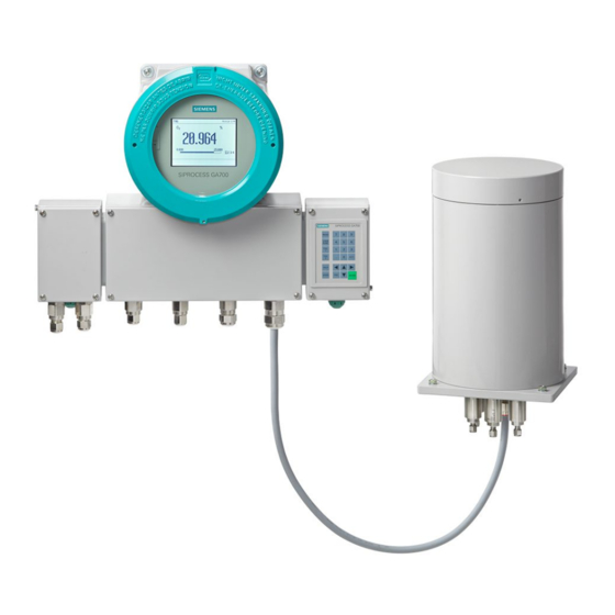
Continuous gas analysis
SIPROCESS GA700
Wall-mounted device
Operating Instructions
05/2018
A5E31930403-06
___________________
Introduction
___________________
Safety instructions
___________________
General information
___________________
Description
___________________
Combined operation
___________________
Installing the device
___________
Installing / removing and
connecting analyzer and
option modules
___________________
Connecting the device
___________________
Commissioning
___________________
Operation
___________________
Maintenance and servicing
___________________
Decommissioning,
dismantling and disposal
___________________
Technical specifications
___________________
Dimension drawings
___________________
Appendix
1
2
3
4
5
6
7
8
9
10
11
12
13
14
A
Advertisement
Table of Contents

Related Manuals for Siemens SIPROCESS GA700


Summary of Contents for Siemens SIPROCESS GA700
- Page 1 ___________________ Introduction ___________________ Safety instructions ___________________ Continuous gas analysis General information ___________________ Description SIPROCESS GA700 Wall-mounted device ___________________ Combined operation ___________________ Installing the device Operating Instructions ___________ Installing / removing and connecting analyzer and option modules ___________________ Connecting the device...
- Page 2 Note the following: WARNING Siemens products may only be used for the applications described in the catalog and in the relevant technical documentation. If products and components from other manufacturers are used, these must be recommended or approved by Siemens. Proper transport, storage, installation, assembly, commissioning, operation and maintenance are required to ensure that the products operate safely and without any problems.
-
Page 3: Table Of Contents
Table of contents Introduction ............................. 9 Purpose of this document ......................9 History ............................9 Purpose ........................... 10 Field of application ........................10 Proper use ..........................11 Qualified personnel ......................... 11 Checking delivery ........................11 Transportation and storage ..................... 12 Warranty conditions ........................ - Page 4 Table of contents CALOMAT 7 ........................... 32 4.6.1 Module design ........................32 4.6.2 How the CALOMAT 7 works ....................33 Option modules ........................33 Combined operation ..........................35 Slots for analyzer modules ..................... 35 Operating modes........................36 5.2.1 Setting note ..........................36 5.2.2 Serial/parallel operation ......................
- Page 5 Table of contents 7.7.3 Installing "Options" terminal block ..................72 Wiring option modules ......................75 Connecting the device ........................... 79 Gas connections ........................79 8.1.1 General safety instructions on gas connection ............... 79 8.1.2 Connection information ......................80 8.1.3 Installing/removing the sample gas restrictor ................. 82 8.1.4 Gas connections at the device ....................
- Page 6 Table of contents Operation ............................. 121 Maintenance and servicing ........................123 11.1 General safety instructions ....................123 11.2 General information on maintenance ................... 125 11.3 Cleaning the device ......................125 11.4 Maintaining analyzers ......................125 11.5 Replacing seals ........................126 11.6 Replacing the basic device ....................
- Page 7 Table of contents Technical support ........................175 Return procedure ........................176 Index..............................177 Wall-mounted device Operating Instructions, 05/2018, A5E31930403-06...
- Page 8 Table of contents Wall-mounted device Operating Instructions, 05/2018, A5E31930403-06...
-
Page 9: Introduction
Introduction Purpose of this document These operating instructions include all the necessary information on the operating principle and the safe usage of the device. These are instructions on the mounting, commissioning, operation, servicing, decommissioning and dismantling of the device. These operating instructions are intended for qualified personnel who have been instructed in all work on a device in non-hazardous areas and in possible dangers arising from improper conduct and who have been trained. -
Page 10: Purpose
"Devices in explosion-proof designs", see "Table A-6 References 5 - Compact Operating Instructions Ex (Page 160)". A SIPROCESS GA700 wall-mounted device consists of an enclosure for wall mounting into which up to two replaceable analysis modules can be inserted. The analyzer modules are selected according to the measuring task and local conditions. -
Page 11: Proper Use
Introduction 1.5 Proper use The following table provides an overview of the device versions: Table 1- 2 SIPROCESS GA700 device with analyzer modules Device variants MLFB number Basic device: Wall-mounted device 7MB3000-3****-**** 7MB3000-4****-**** Analyzer modules, standard version: OXYMAT 7 7MB3020-0***0-*AA*... -
Page 12: Transportation And Storage
Introduction 1.8 Transportation and storage 4. Check the scope of delivery for correctness and completeness on the basis of the delivery note. Compare the serial numbers on the delivery note with the serial numbers on the basic device or on the analyzer modules. 5. -
Page 13: Warranty Conditions
All obligations on the part of Siemens AG are contained in the respective sales contract, which also contains the complete and solely applicable liability provisions. The provisions defined in the sales contract for the responsibility for defects are neither extended nor limited by the remarks in this document. - Page 14 Introduction 1.9 Warranty conditions Wall-mounted device Operating Instructions, 05/2018, A5E31930403-06...
-
Page 15: Safety Instructions
Safety instructions Requirements for safe use In terms of safety, this device left the factory in perfect condition. In order to maintain this status and to ensure safe operation of the device, observe these operating instructions and all the information relevant to safety. Observe the information and symbols on the device. -
Page 16: Conformity With European Directives
Safety instructions 2.2 Basic safety instructions 2.1.2 Conformity with European directives The CE marking on the device shows conformity with the regulations of the following European guidelines: Electromagnetic compatibility Directive of the European Parliament and of the Council EMC 2014/30/EU of 26 February 2014 on the harmonization of the laws of the Member States relating to electromagnetic compatibility (new version) - Page 17 Safety instructions 2.2 Basic safety instructions WARNING Device modifications Danger to personnel, system and the environment can result from modifications and repairs to the device. • Only carry out modifications or repairs that are described in the operating instructions for the device.
- Page 18 Safety instructions 2.2 Basic safety instructions Wall-mounted device Operating Instructions, 05/2018, A5E31930403-06...
-
Page 19: General Information
If you want to use the device under special ambient conditions, for example, in nuclear power plants or for research and development purposes, we recommend: First contact your local SIEMENS partner or our application department. Explain the specific application and clarify the operating conditions. Wall-mounted device... -
Page 20: Automatic Reset
10 seconds for older devices to switch over, and up to 100 seconds to switch to safe operating mode. If you are using SIPROCESS GA700 devices in critical processes, observe the following information: ● Monitor the limits externally via the control system. -
Page 21: Description
Description Overview Wall-mounted devices have a modular structure. A wall-mounted device consists of a wall enclosure and at least one analyzer module. Optionally, wall-mounted devices can be fitted with option modules Definition wall-mounted device and wall enclosure The following terms are used in the operating Instructions: ●... -
Page 22: Structure Of The Wall Enclosure
Description 4.2 Structure of the wall enclosure Structure of the wall enclosure ① ⑨ Door Ethernet cable gland (only metal version) ② ⑩ Fastening hole for securing screw door (6 Purging gas connection outlet (optional) units) ③ ⑪ Display Equipotential bonding connection ④... -
Page 23: Device/Module Identification
Description 4.3 Device/module identification The device is attached to the wall with four screws, see section "Installing the wall-mounted device (Page 56)". ① ③ ④ The door is fitted with a display and a keyboard and is locked via mounting holes ②... -
Page 24: Design Of Module Nameplate
Description 4.3 Device/module identification 4.3.2 Design of module nameplate ① ⑥ Module version Measured component 1 ② ⑦ Article number Measured component 2 optional (ULTRAMAT only) ③ ⑧ Article number suffix Measured component 3 optional ④ ⑨ Serial number DataMatrix Code ECC 200 ⑤... -
Page 25: Oxymat 7
Description 4.4 OXYMAT 7 OXYMAT 7 4.4.1 Module design ① ⑤ Reference gas inlet Power supply connection ② ⑥ Not assigned Connection optional module 2.x (OM2.x) ③ ⑦ Sample gas outlet Connection internal bus communication ④ Sample gas inlet Figure 4-4 Design OXYMAT 7, high-pressure version, measurement gas path with pipes Wall-mounted device Operating Instructions, 05/2018, A5E31930403-06... -
Page 26: Principle Of Operation Of Oxymat 7
Description 4.4 OXYMAT 7 4.4.2 Principle of operation of OXYMAT 7 Overview ① ⑦ Reference gas inlet Paramagnetic measurement effect ② ⑧ Restrictors Electromagnet with alternating current strength ③ ⑨ Microflow sensor Sample gas and reference gas outlet ④ ⑩ Reference gas channels Vibration compensation system (optional) ⑤... - Page 27 Description 4.4 OXYMAT 7 Measuring principle In contrast to other gases, oxygen is highly paramagnetic. OXYMAT 7 analyzer modules use this physical property to determine the oxygen concentration in gases. Oxygen molecules in an inhomogeneous magnetic field always move toward the higher field strength.
-
Page 28: Reference Gas Monitoring
• For changes to the sample gas pressure, contact the Service. • Have the pressure switching point of the reference gas pressure switch adjusted by a Siemens technician or someone trained for this case. See also Reference gas monitoring with pressure switch (Page 111) -
Page 29: Ultramat 7
Description 4.5 ULTRAMAT 7 ULTRAMAT 7 4.5.1 Module design ① ⑤ Sample gas inlet (1) Connection internal bus communication ② ⑥ Sample gas outlet (2) Power supply ③ ⑦ Reference gas outlet (3) Connection optional module 2.x (OM2.x) ④ ⑧ Reference gas inlet (4) Heat sink Figure 4-6... -
Page 30: How The Ultramat 7 Works
Description 4.5 ULTRAMAT 7 4.5.2 How the ULTRAMAT 7 works Overview ① ⑧ Source, adjustable Slider, adjustable ② ⑨ Optical filter Microflow sensor ③ ⑩ Beam splitter Receiver chamber measuring side ④ ⑪ Chopper Sample gas outlet ⑤ ⑫ Reference chamber Measuring chamber ⑥... - Page 31 Description 4.5 ULTRAMAT 7 Measuring principle The ULTRAMAT 7 can simultaneously measure up to 4 infrared-active measuring components. The measurements are based on the molecular-specific absorption of infrared radiation bands (absorption bands). ULTRAMAT 7 analyzer modules use a spectral range which includes wavelengths of 2 to 9 µm.
-
Page 32: Reference Gas Monitoring
Description 4.6 CALOMAT 7 4.5.3 Reference gas monitoring Only the device versions of the ULTRAMAT 7 with a flow-type reference end are equipped with reference gas connections. The reference gas connections are implemented as nozzles with an outer diameter of 6 mm. To connect the reference gas supply and return lines use only such gas-contacted connecting parts that are suitable for the connection and the reference gas. -
Page 33: How The Calomat 7 Works
Description 4.7 Option modules 4.6.2 How the CALOMAT 7 works Overview ① Sample gas inlet ② Measuring membrane with thin-film resistors ③ Sample gas outlet Figure 4-9 Principle of operation of CALOMAT 7 How it works/measuring principle The measuring method is based on the different levels of thermal conductivity of gases. CALOMAT 7 analyzer modules work with a micromechanically produced Si chip, the measuring membrane of which is equipped with thin-film resistors. - Page 34 Description 4.7 Option modules Option module 2.1 The option module 2.1 (OM2.1) is a "passive" module whose control is handled by the relevant analyzer module. For every component measured by the analyzer module, the OM2.1 makes an analog output available. This option module also provides three digital outputs per analyzer module with a fixed function assignment.
-
Page 35: Combined Operation
Combined operation Slots for analyzer modules The following figure shows the bottom of the wall-mounted device with two slots for the analyzer modules. ① Slot 1 (AM1), example OXYMAT 7 ② Slot 2 (AM2), example ULTRAMAT 7 Figure 5-1 Slots for analyzer modules, bottom of wall-mounted device Note High temperature analyzer modules The high-temperature analyzer modules OXYMAT 7 and ULTRAMAT 7 are designed solely... -
Page 36: Operating Modes
Combined operation 5.2 Operating modes Operating modes 5.2.1 Setting note Note Operating mode-specific parameter assignment of the gas path in serial/parallel operation Analyzer modules can be operated in series or in parallel. • If you are only using one analyzer module or want to operate two analyzer modules in series, set the value "Shared"... -
Page 37: Changing The Operating Mode
Combined operation 5.3 Gas connections 5.2.4 Changing the operating mode Please observe the following points when switching between the operating modes: ● Check the mounting positions of sample gas restrictors or clamping screws at the sample gas connections. If required, change them in accordance with the selected operating mode. - Page 38 Combined operation 5.3 Gas connections Overview ① Version with pipes: Sample gas bushing with 6 mm nozzles ② Sample gas restrictors ③ Version with hoses: Sample gas bushing with 6 mm nozzles Figure 5-2 Sample gas connections with sample gas restrictors The sample gas connections of the analyzer modules are 6 mm nozzles.
- Page 39 Combined operation 5.3 Gas connections Distinction between sample gas restrictors and clamping screws The sample gas restrictor and clamping screw differ in the bolt head and at the outlet diameter at the bottom end. ● Sample gas restrictor: Slotted screw, outlet diameter 0.5 mm ●...
- Page 40 Combined operation 5.3 Gas connections Overview of mounting position ① Gas connection before installation of sample gas restrictor or clamping screw ② Gas connection after installation of sample gas restrictor or clamping screw ③ Rear clamp ring ④ Front clamp ring ⑤...
-
Page 41: Application Planning
Combined operation 5.4 Application planning Application planning 5.4.1 General safety instructions WARNING Introduction of combustible gases Explosion hazard Devices in standard version are not designed for use in hazardous areas. • Do not use a standard version of the analyzer in hazardous areas. •... -
Page 42: Notes On Applications Planning
Combined operation 5.4 Application planning 5.4.2 Notes on applications planning Note Usability of the device Before you use the device, use the technical specifications to check that your device is suitable for the measuring task. Note Vibrations at the installation site disturb the measured signal When you use OXYMAT 7 and/or ULTRAMAT 7 analyzer modules, vibrations, especially in the frequency range from 6 Hz to 15 Hz, can influence the measured signal. -
Page 43: Operation With At Least One Ultramat 7
Combined operation 5.4 Application planning Table 5- 1 Mounting position of the sample gas restrictor: OXYMAT 7 Operating Sample gas restrictor/clamping screw mode Operation with one Operation with two Operation with two OXYMAT 7 OXYMAT 7 in series OXYMAT 7 in parallel Pressure Install a sample gas re- Install a sample gas re-... -
Page 44: Operation With Different Analyzer Modules
Combined operation 5.4 Application planning 5.4.6 Operation with different analyzer modules OXYMAT 7/ ULTRAMAT 7/ CALOMAT 7 Table 5- 4 Mounting conditions and positions for the sample gas restrictor Operating Sample gas restrictor/clamping screw mode OXYMAT 7/ ULTRAMAT 7 ULTRAMAT 7/ CALOMAT 7 OXYMAT 7/ CALOMAT 7 Pressure OXYMAT 7 must always We recommend flowing the... -
Page 45: Retrofitting Sample Gas Restrictors
Combined operation 5.4 Application planning 5.4.7 Retrofitting sample gas restrictors Retrofitting example: "Pressure operation, serial" for OXYMAT 7/ULTRAMAT 7 When you are replacing the ULTRAMAT 7 with an OXYMAT 7 analyzer module, you must replace the sample gas restrictor in the sample gas inlet with a clamping screw. MGE, VGE Sample gas inlet (MGE), Reference gas inlet (VGE) ①... -
Page 46: Enclosure Purging
Combined operation 5.4 Application planning Retrofitting example "Suction operation, serial" operating mode for OXYMAT 7/ULTRAMAT 7 When you are using the ULTRAMAT 7 and the OXYMAT 7 analyzer module in serial suction operation, you must convert the sample gas restrictor of the OXYMAT 7 analyzer module: Sample gas inlet →... -
Page 47: Sample Gas Disposal
Combined operation 5.5 Plug & measure permitted activities 5.4.9 Sample gas disposal Thin long lines cause flow resistances in the gas paths. Therefore: ● Install the exhaust line as short as possible ● Use an exhaust gas line with a larger diameter Install the exhaust line as vertical as possible to avoid water vapor condensation in the exhaust gas line. -
Page 48: Notes On Configuration Change
Combined operation 5.5 Plug & measure permitted activities 5.5.2 Notes on configuration change NOTICE Damage caused by inadmissible procedure/faulty operations Inadmissible procedure and/or faulty operations can result in damage to the device or its modules/electronic equipment in connection with Plug & Measure. Therefore: •... -
Page 49: Case Differentiations
Combined operation 5.5 Plug & measure permitted activities 5.5.3 Case differentiations Table 5- 5 Plug & Measure - Commissioning Case Description Data synchronization/Action Commissioning, PM without serial Automatic data synchronization number Commissioning, each module has a Automatic data synchronization serial number stored at the factory. None of the modules has been con- nected to another module before Data synchronization: PM parameters are transferred to the AMx (x=1 or 2), parameters of the... - Page 50 Combined operation 5.5 Plug & measure permitted activities Table 5- 7 Plug & Measure installation of a PM into an existing (configured) device / replacement of a PM in an existing (configured) device Case Description Data synchronization/Action The PM electronics is replaced. "-" is Automatic data synchronization , no changed...
- Page 51 Combined operation 5.5 Plug & measure permitted activities Table 5- 9 Plug & Measure - AM slot change Case Description Data synchronization/Action AM1 → Internal swapping of modules be- None changed tween slots is not permitted! AM2 → Install the modules once again in their previous slot and restart the device.
- Page 52 Combined operation 5.5 Plug & measure permitted activities Wall-mounted device Operating Instructions, 05/2018, A5E31930403-06...
-
Page 53: Installing The Device
Note Material compatibility Siemens can provide you with support concerning selection of analyzer components wetted by the process medium. However, the device operator is responsible for the selection of components. Siemens accepts no liability for faults or failures resulting from incompatible materials. - Page 54 Installing the device 6.1 General safety instructions for installation WARNING Insufficient ventilation Risk of fire The device may overheat or start burning in the case of insufficient ventilation. • Make sure that the room is sufficiently ventilated. Refer to the information in section "Technical specifications (Page 141)". NOTICE Improper installation The device can be damaged or destroyed or its functionality impaired through an incorrect...
-
Page 55: Installation Instructions
Installing the device 6.2 Installation instructions NOTICE Direct sunlight Device damage The device can overheat or materials become brittle through the influence of UV radiation. • Protect the device from direct sunlight. • Make sure that the maximum permissible ambient temperature is not exceeded. For more information on this, see section "Technical specifications (Page 141)". -
Page 56: Installing The Wall-Mounted Device
Installing the device 6.3 Installing the wall-mounted device Note Loss of degree of protection in case of open enclosure Damage to device if the enclosure is permanently open or not properly closed. The degree of protection stipulated on the rating plate or in the technical specifications is no longer guaranteed if the device is open or not completely closed. - Page 57 Installing the device 6.3 Installing the wall-mounted device Figure 6-2 Dimensions with open wall-mounted device Procedure 1. Drill four holes into the wall. The dimensions for the drill holes are specified in the drilling pattern. 2. Insert the anchors in the drilled holes. 3.
- Page 58 Installing the device 6.3 Installing the wall-mounted device Wall-mounted device Operating Instructions, 05/2018, A5E31930403-06...
-
Page 59: Installing / Removing And Connecting Analyzer And Option Modules
Installing / removing and connecting analyzer and option modules General safety instructions for configuration change WARNING Dangerous voltage at open device Danger of electrocution when the enclosure is opened or enclosure parts are removed • Keep the device closed during operation •... -
Page 60: Wall Housing Tool
Installing / removing and connecting analyzer and option modules 7.2 Wall housing tool Wall housing tool The following tools are required for the mounting/removal of the analyzer module in the wall enclosure: Table 7- 1 Wall housing tool Designation Quantity Screwdriver Torx T25 Torx T20... - Page 61 Installing / removing and connecting analyzer and option modules 7.3 Cables CAN bus cable NOTICE Confusing the connectors when connecting the modules When connecting the modules to the CAN bus, confusing the connectors can lead to error messages to the device. •...
-
Page 62: Installation Of Analyzer Modules
Installing / removing and connecting analyzer and option modules 7.4 Installation of analyzer modules Installation of analyzer modules Overview ① ④ Wall-mounted device Flat seal ② ⑤ Door screw (6 units) Torx screw enclosure floor (8 units) ③ ⑥ Equipotential bonding OXYMAT 7 analyzer module cable Figure 7-2... - Page 63 Installing / removing and connecting analyzer and option modules 7.4 Installation of analyzer modules ③ 3. Remove the equipotential bonding cable from the blank plate of the respective slot. ③ Note: The cable is no longer required for equipotential bonding after the analyzer ⑥...
-
Page 64: Connecting Analyzer Modules
Installing / removing and connecting analyzer and option modules 7.5 Connecting analyzer modules Connecting analyzer modules 7.5.1 Connecting OXYMAT 7 Overview ① ③ CAN interface, 12-pin ribbon cable Interface, 26-pin ribbon cable to option mod- ule OM 2.1/2.2 ② Connector for cable from power supply unit Figure 7-4 Analyzer module printed circuit board, interfaces OXYMAT 7 Procedure... -
Page 65: Connecting The Ultramat 7
Installing / removing and connecting analyzer and option modules 7.5 Connecting analyzer modules 7.5.2 Connecting the ULTRAMAT 7 Overview ① ③ CAN interface, 12-pin ribbon cable Interface, 26-pin ribbon cable to adapter card ② Connector for cable from power supply unit Figure 7-5 Analyzer module printed circuit board, interfaces ULTRAMAT 7 Procedure... -
Page 66: Connecting Calomat 7
Installing / removing and connecting analyzer and option modules 7.5 Connecting analyzer modules 7.5.3 Connecting CALOMAT 7 Overview ① ③ CAN interface, 12-pin ribbon cable Interface, 26-pin ribbon cable to option mod- ule OM 2.1/2.2 ② Connector for cable from power supply unit Figure 7-6 AM PCB interface CALOMAT 7 Procedure... -
Page 67: Removal Of Analyzer Modules
Installing / removing and connecting analyzer and option modules 7.6 Removal of analyzer modules Removal of analyzer modules Overview ① ④ Wall-mounted device Flat seal ② ⑤ Door screw (6 units) Torx screw enclosure floor (8 units) ③ ⑥ Equipotential bonding cable OXYMAT 7 analyzer module Figure 7-7 Removing an analyzer module, example OXYMAT 7... -
Page 68: Installing Option Modules
Installing / removing and connecting analyzer and option modules 7.7 Installing option modules 3. Remove the following cables: – Power cable to the analyzer module printed circuit board and power supply unit – 12-pin ribbon cable (CAN) to the analyzer module printed circuit board and the processing unit –... - Page 69 Installing / removing and connecting analyzer and option modules 7.7 Installing option modules ③ Install option module OM 1.1 at mounting location , and option module OM 2.1 or OM 2.2 ② at mounting location ① ③ Electronics base plate Mounting location OM 1.1 ②...
-
Page 70: Installing Option Modules
Installing / removing and connecting analyzer and option modules 7.7 Installing option modules 7.7.2 Installing option modules Preparing for installation ① ⑦ Power cable Connecting cable TB - PU ② ⑧ 12-pin ribbon cable to the AM (CAN bus) Connecting cable TB - OM 1.1 ③... - Page 71 Installing / removing and connecting analyzer and option modules 7.7 Installing option modules 3. Loosen the three screws and remove the shield plate for signal cables (see the figure below). 4. Pull out the connectors for the following cables depending on the installation situation: ①...
-
Page 72: Installing "Options" Terminal Block
Installing / removing and connecting analyzer and option modules 7.7 Installing option modules ① 4. Insert the option module at the respective mounting location into the electronics base ⑥ plate ⑤ Fasten the option module with the two screws with a torque of 1.3 Nm. ③... - Page 73 Installing / removing and connecting analyzer and option modules 7.7 Installing option modules Preparing for installation ① ④ Screw shield plate Screw shield plate ⑤ ② ⑥ Screw, cable gland plate "Standard" terminal block on the cable gland plate ③ ⑦...
- Page 74 Installing / removing and connecting analyzer and option modules 7.7 Installing option modules Performing installation ① ③ "Options" terminal block Connecting cable terminal blocks ② "Standard" terminal block Figure 7-12 Inserting and connecting terminal blocks 1. Inserting the terminal block: ①...
-
Page 75: Wiring Option Modules
Installing / removing and connecting analyzer and option modules 7.8 Wiring option modules Wiring option modules Overview ① Analyzer module printed circuit board ② Interface Figure 7-13 Connecting option modules based on the example of an OXYMAT 7 Note ULTRAMAT 7: Deviating position of the OM2.x connections With ULTRAMAT 7 analyzer modules the connector of the option module is not on the printed circuit board but is on an additional circuit board. - Page 76 Installing / removing and connecting analyzer and option modules 7.8 Wiring option modules Procedure 1. Connect the option modules as follows after installation: – OM 1.1 to the processing unit using the 50-pin ribbon cable – OM 2.x: Use the following cables to connect the OM2.x: Option Cables module...
- Page 77 Installing / removing and connecting analyzer and option modules 7.8 Wiring option modules Figure 7-15 Assignment of the option modules to the terminal blocks – OM 1.1 using the 25-pin connecting cable OM1.1 - TB: ④ ⑫ ⑥ ⑮ ↔ ↔...
- Page 78 Installing / removing and connecting analyzer and option modules 7.8 Wiring option modules Wall-mounted device Operating Instructions, 05/2018, A5E31930403-06...
-
Page 79: Connecting The Device
Connecting the device Gas connections 8.1.1 General safety instructions on gas connection WARNING Introduction of toxic, corrosive or flammable gases The limited release of toxic or corrosive gases during their introduction cannot be avoided with absolute certainty. • Before toxic, corrosive or flammable gases are introduced, carry out a leak test for the pipe connections. -
Page 80: Connection Information
Connecting the device 8.1 Gas connections 8.1.2 Connection information Note Identifier of the gas connections The identifiers of the gas connections are imprinted as numbers 1 to 4 on the module plate. Note Pipes Connect the pipes with the gas connections using suitable clamping screws. Use only such connecting parts (pipes, threaded joints, etc.) coming into contact with sample gas that are resistant to the sample gas. - Page 81 Connecting the device 8.1 Gas connections Note Reference gas connection Connection for an external reference gas pump (low pressure connection): • The gas connections (4 and 3) are stainless steel pipes with a diameter of 6 mm. Connection 4 (inlet) is connected to an external pump with a discharge pressure of 100 hPa to 150 hPa.
-
Page 82: Installing/Removing The Sample Gas Restrictor
Connecting the device 8.1 Gas connections Note Unstable measured value display due to pressure surges Pressure surges can result in unstable measured value displays when the sample gas flow is superimposed by fast pressure fluctuations or a sample gas pump delivers sample gas into the device. -
Page 83: Gas Connections At The Device
Connecting the device 8.1 Gas connections 8.1.4 Gas connections at the device 8.1.4.1 OXYMAT 7 Arrangement of the gas connections in the wall-mounted device ① Purge gas inlet ② Purge gas outlet ③ Slot of analyzer module 2 ④ Slot of analyzer module 1: OXYMAT 7 Sample gas inlet Sample gas outlet Not assigned, bypass outlet for version with external reference gas pump... - Page 84 Connecting the device 8.1 Gas connections Heated OXYMAT 7 Arrangement of the gas connections in the wall-mounted device ① Purge gas inlet ② Purge gas outlet ③ Reference gas inlet ④ Sample gas outlet ⑤ Sample gas inlet Figure 8-2 OXYMAT 7 gas connections high-temperature in the wall mounted device, lower side Design of the gas connections Gas connection...
-
Page 85: Ultramat 7
Connecting the device 8.1 Gas connections 8.1.4.2 ULTRAMAT 7 Arrangement of the gas connections ① Purge gas inlet ② Purge gas outlet ③ Slot of analyzer module 2 ④ Slot of analyzer module 1: ULTRAMAT 7 Sample gas inlet Sample gas outlet Reference gas outlet Reference gas inlet Atmospheric pressure sensor... -
Page 86: Calomat 7
Connecting the device 8.1 Gas connections 8.1.4.3 CALOMAT 7 Arrangement of the gas connections ① Purge gas inlet ② Purge gas outlet ③ Slot of analyzer module 2 ④ Slot of analyzer module 1: CALOMAT 7 Sample gas inlet Sample gas outlet Not assigned Not assigned Figure 8-4... -
Page 87: Purging Gas Connections
Connecting the device 8.1 Gas connections 8.1.4.4 Purging gas connections Overview When measuring toxic or corrosive gases, the gas path may start to leak and sample gas can accumulate in the device. This means that devices, in particular those that are used in hazardous areas, must be purged with purging gas (oil-free dry air or inert gas). -
Page 88: Connecting Gas
Connecting the device 8.2 Electrical connections Design of the gas connections Dimensions of purging gas couplings Diameter Exterior 12 mm Length Without sealing caps 28 mm With sealing caps 41 mm 8.1.5 Connecting gas Procedure 1. Connect the gas lines by means of suitable clamping ring screwed connections to the associated gas inlets and outlets. - Page 89 Connecting the device 8.2 Electrical connections WARNING Danger due to electrical current The power cable to be connected at the customer location could be damaged by improper connection to the device. • Check whether the existing line voltage corresponds to the line voltage specified on the nameplate of the device or in the technical specifications.
-
Page 90: Connection Information
Connecting the device 8.2 Electrical connections 8.2.2 Connection information Note Connection requirements The power cable must comply with the valid regulations and conditions for the place of installation and be provided with a protective conductor at the potential of the enclosure. The cross-section of each wire must be ≥... -
Page 91: Requirements For Electrical Connection
Connecting the device 8.2 Electrical connections Note Securing plug-in connections Plug-in connections without interlock can loosen and fall out. • Secure plug-in connections without interlock mechanically, for example, with a cable tie. 8.2.3 Requirements for electrical connection ● You have ensured that a readily accessible power disconnection device is located in the direct vicinity of the device. -
Page 92: Connecting The Signal Cables
Connecting the device 8.2 Electrical connections 8.2.4 Connecting the signal cables Overview ① Screws for door ② Shielding plate ③ Cable glands for signal lines (7 pieces) ④ Power supply cable gland Figure 8-6 Wall-mounted device, connecting signal cables Procedure ①... -
Page 93: Connecting The Ethernet Cable
Connecting the device 8.2 Electrical connections ③ 5. Insert the signal cable through this cable gland 6. Insert the stripped conductors of the signal cable into the terminal block in accordance with the terminal assignment. ③ 7. Fasten the signal cable in the cable gland . - Page 94 Connecting the device 8.2 Electrical connections 2. Fasten the prepared gland at the device: ⑥ Plate with cable glands ⑦ Position cable gland Ethernet cable (underside of the device) Figure 8-8 Ethernet cable: Position of the cable gland ⑦ ⑥ –...
-
Page 95: Connecting The Power Supply
Connecting the device 8.2 Electrical connections 8.2.6 Connecting the power supply Overview ① ④ Power supply unit Shielding plate ② ⑤ Appliance plug Power supply cable gland ③ ⑥ Screws for door Equipotential bonding Figure 8-9 Wall-mounted device, connecting power supply Wall-mounted device Operating Instructions, 05/2018, A5E31930403-06... -
Page 96: Electrical Connections And Terminal Assignment
Connecting the device 8.2 Electrical connections Procedure ③ 1. Undo the six screws and open the door of the wall-mounted device. ④ 2. Remove the shielding plate on the right side panel. To do this loosen the screws. ⑤ 3. Unscrew the union nut of the cable gland ⑤... - Page 97 Connecting the device 8.2 Electrical connections Figure 8-10 Pin assignment of standard terminal block, terminal rows A and B Wall-mounted device Operating Instructions, 05/2018, A5E31930403-06...
- Page 98 Connecting the device 8.2 Electrical connections Figure 8-11 Pin assignment of standard terminal block, terminal rows C and D Note Limited number of analog outputs Because of the functional principle, only a limited number of analog outputs is available. Wall-mounted device Operating Instructions, 05/2018, A5E31930403-06...
- Page 99 Connecting the device 8.2 Electrical connections Figure 8-12 Options for the assignment of the terminal block, terminal rows A and B Wall-mounted device Operating Instructions, 05/2018, A5E31930403-06...
-
Page 100: Spark Suppression: This Example
Connecting the device 8.2 Electrical connections Figure 8-13 Options for the assignment of the terminal block, terminal rows C and D 8.2.8 Spark suppression: This Example NOTICE Damage to the digital outputs due to missing external protective circuit Arcs can result when switching inductances without external protective circuit; these can damage the digital outputs/relays. - Page 101 Connecting the device 8.2 Electrical connections ① Standard terminal block, terminal row A: Function in the analyzer ② Terminal end/spark suppression ③ Power supply unit Digital outputs: Contact load max. 24 V/1.7 A, AC/DC. Shown relay contacts: relay coil has zero current Figure 8-14 Wall-mounted device: Example of spark suppression on a relay contact...
- Page 102 Connecting the device 8.2 Electrical connections Wall-mounted device Operating Instructions, 05/2018, A5E31930403-06...
-
Page 103: Commissioning
Commissioning General safety instructions for commissioning WARNING Commissioning and operation with error message If an error message is displayed, correct operation in the process is no longer guaranteed. • Check to see which error is pending. • Correct the error. •... - Page 104 Commissioning 9.1 General safety instructions for commissioning CAUTION Hot surfaces resulting from hot sample gases and heated devices Danger of burns resulting from surface temperatures above 70 °C (155 °F). • Take appropriate protective measures, for example contact protection. • Make sure that the maximum ambient temperature is not exceeded by implementing protective measures.
-
Page 105: General Information On Commissioning
Commissioning 9.2 General information on commissioning General information on commissioning Note Ambient temperature Ensure that the ambient temperature is within the permissible range during operation. The corresponding information is available in the section "Technical specifications". The technical specifications of the device can deviate outside these temperature limits. Operability of the device is no longer ensured at deviations of more than 5 K. - Page 106 Commissioning 9.2 General information on commissioning Note Combined operation with ULTRAMAT 7: Signal frequency of the OXYMAT 7 If you use an OXYMAT 7 and an ULTRAMAT 7 analyzer module in combined operation, the default OXYMAT 7 signal frequency can have a negative influence on the ULTRAMAT 7 analyzer module.
-
Page 107: Gas Preparation
Commissioning 9.3 Gas preparation Note Enable analog and digital outputs If you subsequently install an option module 2.1, you must enable the analog and digital outputs using SIMATIC PDM after restarting: 1. Establish a connection between SIMATIC PDM and the analyzer. You may have to log on at the Expert level. -
Page 108: Oxymat 7 / Ultramat 7: Introduction Of Reference Gas
Commissioning 9.4 OXYMAT 7 / ULTRAMAT 7: Introduction of reference gas Ensure that gas sampling devices, gas cooling devices, condensate vessels, filters and any connected controllers, recorders or indicators are ready to operate (see the associated operating instructions). In the case of toxic, corrosive and/or combustible gases, ensure the suitability for use of the components. -
Page 109: Ultramat 7
Commissioning 9.4 OXYMAT 7 / ULTRAMAT 7: Introduction of reference gas Overview Table 9- 1 Overview of the reference gases Measuring range Recommended Reference gas connection Comment reference gas pressure range 0 to vol. % O 2 000 to 4 000 hPa above The reference gas flow sample gas pressure is set automatically to... -
Page 110: Requirements For Reference Gas From The Gas Cylinder
Commissioning 9.4 OXYMAT 7 / ULTRAMAT 7: Introduction of reference gas In an analyzer module with a physically suppressed zero point, use an appropriate reference gas. The concentration of the reference gas generally corresponds to the characteristic initial value or, in special cases, the full-scale value or intermediate values. In order to compensate for interference, the reference gas compartment can be subjected to the purified sample gas of the measured component (absorber mode) or gas out of the cylinder, which corresponds to the average interference gas composition. -
Page 111: Reference Gas Monitoring With Pressure Switch
• Contact the Service. • Have the pressure switching point of the reference gas pressure switch adjusted by a Siemens technician or someone trained for this scenario. Checking pressure switch for function 1. Increase the reference gas pressure until the pressure switch is triggered, meaning that the switch contact opens. -
Page 112: Oxymat 7
Commissioning 9.5 Zero point error 9.5.1 OXYMAT 7 Accompanying gases (interfering gases) cause a zero point deviation that is positive with paramagnetic gases and negative with diamagnetic gases. The extent of this offset per 100 vol. % accompanying gas, expressed in vol. % O absolute, is listed in the following table. - Page 113 Commissioning 9.5 Zero point error Table 9- 4 Zero point error of noble gases Accompanying gas (concentration 100 vol. %) Zero point deviation in vol. % O absolute Helium +0.33 Neon +0.17 Argon -0.25 Krypton -0.55 Xenon -1.05 Table 9- 5 Zero point error of inorganic gases Accompanying gas (concentration 100 vol.
-
Page 114: Calomat 7
Commissioning 9.5 Zero point error Information on interference gas correction is available in the following operating manuals: ● Operating with the Local User Interface Table A-2 References 1 - Operating Manuals LUI (Page 159) ● Operation with SIMATIC PDM Table A-3 References 2 - Operating Manuals PDM (Page 159) 9.5.2 CALOMAT 7... -
Page 115: Checking Gas Paths For Leaks
Commissioning 9.6 Checking gas paths for leaks More information on correction of cross-interference is available in the following operating manuals: ● Operating with the Local User Interface Table A-2 References 1 - Operating Manuals LUI (Page 159) ● Operation with SIMATIC PDM Table A-3 References 2 - Operating Manuals PDM (Page 159) Checking gas paths for leaks 9.6.1... -
Page 116: Recommended Test Setup
Commissioning 9.6 Checking gas paths for leaks 9.6.2 Recommended test setup Arrangement of the gas connections The figure below is a schematic view of the gas connections: Sample gas inlet Sample gas outlet ULTRAMAT 7: Reference gas outlet OXYMAT 7 / CALOMAT 7: Not assigned, screw-type blank cap OXYMAT 7 / ULTRAMAT 7: Reference gas inlet CALOMAT 7: Not assigned, screw-type blank cap Figure 9-1... -
Page 117: Checking Oxymat 7 For Leaks
Commissioning 9.6 Checking gas paths for leaks 9.6.3 Checking OXYMAT 7 for leaks Procedure: Devices with pipes 1. Close the reference gas inlet. 2. Connect a pressure measuring instrument (manometer) to the sample gas outlet. 3. Carefully apply pressure of approximately 3 000 hPa (absolute pressure) to the measuring inlet. -
Page 118: Checking Calomat 7 For Leaks
Commissioning 9.6 Checking gas paths for leaks Note Test values The test values have been defined under the assumption that the total volume of the gas path in the analyzer module and in the connection line of the pressure measuring device amounts to 80 ml. -
Page 119: Requirements For Startup
Commissioning 9.7 Requirements for startup Requirements for startup You have ensured that ● The device has at least one analyzer module, ● All required gas lines and facilities are connected to the device and are checked for leaks and tightness with an overpressure, ●... - Page 120 Commissioning 9.8 Commissioning the device Wall-mounted device Operating Instructions, 05/2018, A5E31930403-06...
-
Page 121: Operation
Operation Information on operation of the wall-mounted device is included in the operating manuals: ● Operating with the Local User Interface, see Table A-2 References 1 - Operating Manuals LUI (Page 159) ● Operation with SIMATIC PDM, see Table A-3 References 2 - Operating Manuals PDM (Page 159) Wall-mounted device Operating Instructions, 05/2018, A5E31930403-06... - Page 122 Operation Wall-mounted device Operating Instructions, 05/2018, A5E31930403-06...
-
Page 123: Maintenance And Servicing
Maintenance and servicing 11.1 General safety instructions WARNING Dangerous voltage at open device Danger of electrocution Danger of electrocution exists when the enclosure is opened or enclosure parts are removed. • Before you open the enclosure or remove enclosure parts, deenergize the device and wait another 10 minutes. - Page 124 Maintenance and servicing 11.1 General safety instructions WARNING Danger of suffocation by inert gas Inert gas in the enclosure can cause danger of suffocation. The enclosure also contains a flammable substance which is within the flammable range when it comes into contact with air.
-
Page 125: General Information On Maintenance
Maintenance and servicing 11.2 General information on maintenance 11.2 General information on maintenance Depending on the use of the device and certain empirical values, determine a maintenance interval for the tests to be carried out repeatedly. The maintenance intervals will vary from site to site depending on corrosion resistance. 11.3 Cleaning the device Cleaning the surface... -
Page 126: Replacing Seals
Maintenance and servicing 11.5 Replacing seals 11.5 Replacing seals Overview ① Sealing set (flat seals) ② Shield cable glands ③ Door seal Figure 11-1 Seals Wall-mounted device Operating Instructions, 05/2018, A5E31930403-06... - Page 127 Maintenance and servicing 11.5 Replacing seals Replacing door seals 1. Isolate the device from power. 2. Loosen the six screws and open the door. 3. Remove the ribbon cable to the LUI printed circuit board and the cable for equipotential bonding at the door.
-
Page 128: Replacing The Basic Device
Maintenance and servicing 11.6 Replacing the basic device NOTICE Damage to the device through pulling the latched cable Cables for equipotential bonding are equipped at their two ends with latching plug-in connectors. Pulling on a latched cable can cause the plug-in connector to be torn off or its contacts to be damaged. - Page 129 Maintenance and servicing 11.6 Replacing the basic device Mounting the device 1. Mount the new basic device. 2. Install the previously used analyzer modules (AM) into the new basic device and connect these. Proceed as described in sections "Installation of analyzer modules (Page 62)" and "Connecting analyzer modules (Page 64)".
-
Page 130: Replacing The Processing Module
Maintenance and servicing 11.7 Replacing the processing module 11.7 Replacing the processing module Procedure ① ⑦ Power cable Connecting cable TB - PU ② ⑧ 12-pin ribbon cable to the AM (CAN bus) Connecting cable TB - OM 1.1 ③ ⑨... - Page 131 Maintenance and servicing 11.7 Replacing the processing module ③ ⑯ Processing module (PM) Screws (2 units) ⑬ ⑰ Screw Electronics base plate ⑭ ⑱ Printed circuit board holder Screw ⑮ ⑲ Screw Shielding plate Figure 11-4 Replacing the processing unit 1.
- Page 132 Having different IP addresses after replacing the processing module can prevent network communication with the device. If you install a new processing module in the SIPROCESS GA700 device, the following IP address is set as default in the factory: 192.168.0.2. Before you set up a network connection to the device, follow the steps below: •...
-
Page 133: Replacing Option Modules
Maintenance and servicing 11.8 Replacing option modules 11.8 Replacing option modules You can find information on replacing option modules in the section "Installing option modules (Page 68)". Wall-mounted device Operating Instructions, 05/2018, A5E31930403-06... -
Page 134: Replacing The Cable Gland Set
Maintenance and servicing 11.9 Replacing the cable gland set 11.9 Replacing the cable gland set Procedure ① ③ Shielding plate Screw for fastening the cable gland plate to the side panel of the housing ② ④ Screws shield plate (3 units) Complete cable gland set Figure 11-5 Replacing the cable gland set... - Page 135 Maintenance and servicing 11.9 Replacing the cable gland set ② ① 3. Loosen the three screws and remove the shield plate ③ 4. Loosen the screw on the inside of the right side panel and the eleven hex nuts at the bottom of the enclosure.
-
Page 136: Eliminating Faults And Errors
Maintenance and servicing 11.10 Eliminating faults and errors 11.10 Eliminating faults and errors Table 11- 1 Error messages Fault message Description Measures Invalid device con- No analyzer module was detected. At least one analyzer module is Install at least one analyzer figuration required to use the device. -
Page 137: Decommissioning, Dismantling And Disposal
Decommissioning, dismantling and disposal 12.1 Safety instructions for decommissioning WARNING Incorrect disassembly The following dangers may result through incorrect disassembly: - Injury through electric shock - Danger through emerging media when connected to the process - Danger of explosion in hazardous area Observe the following for correct disassembly: •... -
Page 138: Decommissioning The Device
Decommissioning, dismantling and disposal 12.2 Decommissioning the device WARNING Danger from gas lines under pressure Danger of injury during maintenance work Hot, toxic or corrosive sample gases can be released when the gas lines are opened. Prevent gases from exiting prior to opening or removing the device. •... -
Page 139: Dismantling The Device
Decommissioning, dismantling and disposal 12.3 Dismantling the device 12.3 Dismantling the device Requirement The device is decommissioned. Procedure Wall-mounted device 1. Remove the fastening screws 2. Remove the wall-mounted device. 12.4 Disposing of the device The device has to be fully emptied before the disposal. When disposing of the device observe the statutory regulations applying in the respective country of use (for example guidelines on the disposal of electronic waste). - Page 140 Decommissioning, dismantling and disposal 12.5 Information on recycling Wall-mounted device Operating Instructions, 05/2018, A5E31930403-06...
-
Page 141: Technical Specifications
Technical specifications 13.1 Determining the technical specifications The technical specifications are obtained based on the specifications of DIN EN 61207-1. Unless specified otherwise, the data listed below relates to the following measurement conditions. Technical specifications OXYMAT 7 ULTRAMAT 7 CALOMAT 7 Ambient temperature 25 °C Ambient pressure... - Page 142 Technical specifications 13.2 Technical specifications of the wall housing Electrical characteristics EMC interference im- with one and/or in accordance with the standard requirements of munity (electromagnetic two OXYMAT 7 / NAMUR NE21 (05/2006) and EN 61326-1 (2013) compatibility) ULTRAMAT 7 during operation: units with one or two...
-
Page 143: Technical Specifications Of Analyzer Modules
Technical specifications 13.3 Technical specifications of analyzer modules Table 13- 5 Wall housing: Option modules Option modules Option module 1.1 12 digital outputs, with changeover contacts, max. load: 24 V AC/DC/1.7 A (total load for all 12 relay outputs in continu- ous operation max. - Page 144 Technical specifications 13.3 Technical specifications of analyzer modules Table 13- 8 OXYMAT 7: Measuring ranges Measuring ranges OXYMAT 7 OXYMAT 7 high-temperature Number of measuring ranges Max. 4; parameters can be Max. 4; parameters can be as- assigned freely signed freely Parameters can Smallest 0.5%, 1%, 2% or 5% O...
- Page 145 Technical specifications 13.3 Technical specifications of analyzer modules Gas inlet conditions Sample gas temperature and humidity OXYMAT 7 standard version 0 to 60 °C with relative humidity < 90%, avoid condensation in the gas path (moisture content results in measurement errors) OXYMAT 7 high-temperature 0 ...
- Page 146 Technical specifications 13.3 Technical specifications of analyzer modules Measuring response Repeatability At the zero point ≤ ±0.5% of the smallest measuring span/month or ≤ ± 50 vpm O whichever is greater For span gas ≤ ±0.5% of the current measuring span/month or ≤...
- Page 147 Technical specifications 13.3 Technical specifications of analyzer modules Table 13- 14 OXYMAT 7: Climatic conditions Climatic conditions Storage and transport -30 to +70 °C Max. permissible ambient temperature 0 to 50 °C surrounding the basic device during operation Ambient humidity (relative humidity) <...
-
Page 148: Technical Data Ultramat 7
Technical specifications 13.3 Technical specifications of analyzer modules 13.3.2 Technical data ULTRAMAT 7 Table 13- 17 ULTRAMAT 7: General technical specifications General ULTRAMAT 7 ULTRAMAT 7 high-temperature Information on the smallest See module nameplate span Max. power consumption ≤ 30 W ≤... - Page 149 Technical specifications 13.3 Technical specifications of analyzer modules Gas inlet conditions ULTRAMAT 7 standard version 0 ... 50 °C at relative humidity < 90%, in rela- tion to the respective ambient temperature; avoid condensation in gas path (moisture con- tent results in measurement errors) ULTRAMAT 7 high-temperature 0 ...
- Page 150 Technical specifications 13.3 Technical specifications of analyzer modules Table 13- 23 ULTRAMAT 7: Influence variables Influence variables Ambient tempera- Zero point ≤ 1% of smallest measuring range / 2 K ture Measured value ≤ 1% of the current measuring range/10 K Sample gas pres- Without pressure ≤...
-
Page 151: Calomat 7 Technical Specifications
Technical specifications 13.3 Technical specifications of analyzer modules 13.3.3 CALOMAT 7 technical specifications Table 13- 28 CALOMAT 7: General technical specifications General Information on the smallest span See module nameplate Power consumption < 20 W Weight Approx. 3 kg Electrical safety In accordance with DIN EN 61010-1 Max. - Page 152 Technical specifications 13.3 Technical specifications of analyzer modules Table 13- 32 CALOMAT 7: Time response Time response Warm-up period at room temperature < 30 min (max. accuracy after 2 h) Response characteristics Delayed Standard module < 2.5 s display T Module with integrat- <...
- Page 153 Technical specifications 13.3 Technical specifications of analyzer modules Influence variables Accompanying gases (interference The interference gas sensitivity depends on the application gases) and must be determined in each case except for applica- tions with blast furnace gas / converter gas / wood gasifica- tion (pre-adjusted).
-
Page 155: Dimension Drawings
Dimension drawings Figure 14-1 Dimensional drawing of wall enclosure The dimensions are specified in millimeters. Wall-mounted device Operating Instructions, 05/2018, A5E31930403-06... - Page 156 Dimension drawings Wall-mounted device Operating Instructions, 05/2018, A5E31930403-06...
-
Page 157: Appendix
The manufacturer of the gas analyzers listed below is authorized to provide the respective labels with a CE marking: Figure A-1 SIPROCESS GA700 gas analyzers with CE marking The version of the identified product sold by the manufacturer conforms with the directives of the following European guidelines:... -
Page 158: Certificate
EN 61326-1 2006 2006/95/EC EN 61010-1 2010 * " all environments included" Certificate The certificates are available on the Internet at: Certificates (https://support.industry.siemens.com/cs/ww/en/ps/17731/cert). Abbreviations List of abbreviations Table A- 1 List of abbreviations Abbreviation In full Description Amperes Current unit... -
Page 159: References
Watt Unit of electrical power References Table A- 2 References 1 - Operating Manuals LUI Title Languages Article numbers SIPROCESS GA700 German (de-DE) A5E31930441 Operating with the local user interface English (en-US) A5E31930478 Operating manual Table A- 3 References 2 - Operating Manuals PDM... - Page 160 Appendix A.4 References Table A- 5 References 4 - Compact Operating Instructions Title Languages Article numbers SIPROCESS GA700 German (de-DE) A5E31805153 Quick Start English (en-US) A5E31805656 Compact Operating Instructions French (fr-FR) A5E31809624 Italian (it-IT) A5E31809652 Spanish (es-ES) A5E31809707 Portuguese (pt-BR)
-
Page 161: Spare Parts/Accessories
The following spare parts lists were correct at the time this documentation was issued. Interim changes or updates are not included. You can find information about the latest spare parts in the catalogs and on the Internet. If necessary contact your Siemens contact at: Partner (https://www.automation.siemens.com/partner) -
Page 162: Spare Parts Wall-Mounted Device
However, the classification indicates a permission for use: • The use of Class 2 spare parts is allowed only after appropriate training provided by Siemens AG. The use of Class 2 spare parts without prior training voids the manufacturer warranty of the device/module. - Page 163 Appendix A.5 Spare parts/accessories Article number Name Description Classifica- tion A5E03860165 Terminal block options Terminal block options with screws A5E03860170 Display LCD display A5E03862674 Power supply unit Power supply unit with screws and ground cable A5E03860180 Power connector Appliance plug A5E03860189 Connecting cables TB-PU Connecting cable between standard terminal block and...
-
Page 164: Spare Parts Oxymat 7
Appendix A.5 Spare parts/accessories Article number Name Description Classifica- tion A5E33585257 Dummy plugs purging gas For purging gas couplings Ex nozzles Ex A5E43595652 Mounting part wall-mounting Fuse for appliance plug device Ex Table A- 11 Conversion sets wall-mounted device Article number Name Description Classifica-... - Page 165 Appendix A.5 Spare parts/accessories Article number Name Description Classifica- tion A5E41579777 Measuring chamber With vibration compensation, Hastelloy, cleaned for O A5E03790055 O-ring set For measuring chamber, Kalrez A5E41580069 O-ring set For measuring chamber, Kalrez, cleaned for O A5E03790056 Set of screws Standard version A5E03790058 Analyzer unit...
- Page 166 Appendix A.5 Spare parts/accessories Article number Name Description Classifica- tion A5E41588359 Clamping screw For sample gas with pipes, stainless steel, cleaned for O A5E35898424 Clamping screw For sample gas with pipes, Hastelloy A5E41588366 Clamping screw For sample gas with pipes, Hastelloy, cleaned for O A5E03790221 Set for sample gas path FKM / FPM hose...
- Page 167 Appendix A.5 Spare parts/accessories Article number Name Description Classifica- tion A5E03790515 Set of self-locking screws A5E43896751 Module packaging C7-O7-U7 A5E43897960 Module packaging O7, high-temperature model A5E03878052 Set of cables A5E03790507 Analyzer module PCB Standard version A5E35686750 Retaining plate with small For mounting the PCN A5E03790512 or the pressure sen- parts set sor A5E03790214 / A5E03790215...
-
Page 168: Spare Parts Ultramat 7
Appendix A.5 Spare parts/accessories Article number Name Description Classifica- tion A5E43959291 Analyzer unit With vibration compensation, Hastelloy, high-temperature model A5E43959300 Analyzer unit With vibration compensation, Hastelloy, cleaned for O high-temperature model A.5.4 Spare parts ULTRAMAT 7 Table A- 14 Spare parts list ULTRAMAT 7 - IR source Article number Name Description... - Page 169 Appendix A.5 Spare parts/accessories Article number Name Description Classifica- tion A5E44302871 IR source For Ex module, without 2 gas connections, non-flow type, sealed A5E35255673 IR source For standard module, without 4 gas connections, flow-type, sealed A5E44302873 IR source For Ex module, without 4 gas connections, flow type, purged 2 A5E35255656 Terminal block For sample gas, stainless steel...
- Page 170 Appendix A.5 Spare parts/accessories Article number Name Description Classifica- tion A5E35255681 Analyzer chamber 60 mm Al, flow-type A5E35263527 Analyzer chamber 90 mm Al, non-flow-type A5E35255683 Analyzer chamber 90 mm Al, flow-type A5E35263528 Analyzer chamber 180 mm Al, non-flow-type A5E35255685 Analyzer chamber 180 mm Al, flow-type A5E41093568 Analyzer chamber...
- Page 171 Appendix A.5 Spare parts/accessories Article number Name Description Classifica- tion A5E41277169 Analyzer chamber 60 mm Al, non-flow-type, cleaned for O A5E41277263 Analyzer chamber 60 mm Al+Ta FFKM, non-flow-type, cleaned for O A5E41277536 Analyzer chamber 60 mm Al, flow-type, cleaned for O A5E41277563 Analyzer chamber 60 mm Al+Ta FFKM, flow-type, cleaned for O...
- Page 172 Appendix A.5 Spare parts/accessories Article number Name Description Classifica- tion A5E35263535 Pipe 0.2 - 6 mm reference gas, Recommendation: Include O-rings in order; Viton or FFKM A5E41947240 Pipe 0.2 - 6 mm reference gas, cleaned for O Recommendation: Include O-rings in order; Viton or FFKM A5E35263352 Pipe 20 mm sample gas...
- Page 173 Appendix A.5 Spare parts/accessories Article number Name Description Classifica- tion A5E43472881 Pipe 60 mm sample gas Hastelloy A5E43472887 Pipe 60 mm sample gas Hastelloy, cleaned for O A5E41042857 Pipe 90 mm sample gas Hastelloy A5E41263077 Pipe 90 mm sample gas Hastelloy, cleaned for O A5E43472891 Pipe 90 mm sample gas Hastelloy...
-
Page 174: Spare Parts Calomat 7
Appendix A.5 Spare parts/accessories Article number Name Description Classifica- tion A5E35255693 Cable set A5E35255699 Screw set M3x6 A5E35255700 Screw set M4x10 A5E35263268 Screw set M4x16 A5E35263315 Screw set M4x20 A5E35263334 Screw set M5x16 A5E35263344 Screw set M5x45 A5E40871415 Screw set M5x40 A5E39981720 Zero point adjuster... - Page 175 Our bulletin board, where users and specialists share their knowledge worldwide. Additional Support Contact your local Siemens partner if you have any questions about the use of products described in this manual and cannot find the answers here. Find your contact partner at: Partner (https://www.automation.siemens.com/partner)
- Page 176 Check the item after it has been cleaned. Devices/replacement parts without decontamination certificate will be returned to you at your expense. The forms are available on the supplied CD. For more detailed information, refer to Return procedure (https://support.industry.siemens.com/cs/ww/en/sc/4529) Wall-mounted device Operating Instructions, 05/2018, A5E31930403-06...
- Page 177 Index OXYMAT 7 pressure correction, 106 ULTRAMAT 7 pressure correction, 106 " Connecting Ethernet cable wall-mounted device, 93 "Options" terminal block Gas, 88 Installing, 74 Power supply wall-mounted device, 96 Purging gas, wall-mounted device, 87 Signal cables wall-mounted device, 92 Connecting the Ethernet cable Analog current interface, 76 Wall-mounted device, 93...
- Page 178 Index Processing unit Replacing, 130 How it works Proper use, 11 CALOMAT 7, 33 Purging gas OXYMAT 7, 27 wall-mounted device, 87 ULTRAMAT 7, 31 Purpose, 10 Installing Qualified personnel, 11 Dimension drawing wall-mounted device, 56 Requirements, 55 Wall-mounted device, 57 Intended use, 10, (See Device modifications) IP address, 132 Reference gas monitoring...
- Page 179 Index Technical specifications CALOMAT 7, 151 Determining, 141 OXYMAT 7, 143 ULTRAMAT 7, 148 Wall housing, 141 Technical Support, 175 Terminal assignment Wall-mounted device, 96 Test certificates, 15 Tool Wall housing, 60 Warning symbols, 15 Warranty, 13, 13 Wiring and cabling, 60 Zero point error, 112 Wall-mounted device Operating Instructions, 05/2018, A5E31930403-06...
- Page 180 Index Wall-mounted device Operating Instructions, 05/2018, A5E31930403-06...