Advertisement
Quick Links
Advertisement

Related Manuals for Toshiba TCB-IFTH1GUL


Summary of Contents for Toshiba TCB-IFTH1GUL
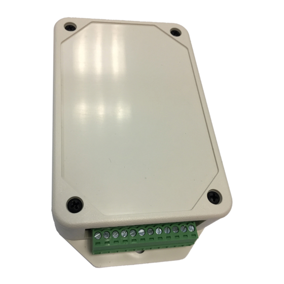
- Page 1 Installation Manual 24V Thermostat Interface FOR INSTALLER Model name: TCB-IFTH1GUL Read this manual before using the TCB- IFTH1GUL • 24V Thermostat Interface. Refer to installation manuals supplied with Indoor Unit, • Remote Controller, and Thermostat for any installation instructions. English...
-
Page 2: Table Of Contents
24V Thermostat Interface Installation Manual Contents Precautions for safety ........................3 Introduction ............................5 1 Installation ............................. 6 2 Settings ............................10 3 Usage ............................13 2-EN... -
Page 3: Precautions For Safety
24V Thermostat Interface Installation Manual Precautions for safety The following instructions must be observed. • Carefully read these "Precautions for Safety" before installation, and perform installation work safely. • These precautions contain important information regarding safety. • After installation work, carry out an operation trial to confirm that there are no problems, and explain to the customer how to operate and maintain the system. - Page 4 24V Thermostat Interface Installation Manual Caution • A double-insulated, separately-shielded, copper conductor with a minimum 600 volt rating must be used between the 24V Thermostat Interface, the Indoor Unit and wired controllers. • Use copper conductors only. • When installing the device in a hospital, communication facility, etc., provide sufficient electrical isolation against electromagnetic interference.
-
Page 5: Introduction
Introduction Overview The 24V Thermostat Interface is an electronic, incorporated control, which allows VRF (Variable Refrigerant Flow) and Light Commercial TOSHIBA Carrier indoor units to utilize 3rd party 24VAC thermostat sold in the US market. Included Items Component... -
Page 6: Installation
24V Thermostat Interface Installation Manual Thermostat Interface Installation 24V Thermostat Interface Installation and Orientation Install the 24V Thermostat Interface on a flat surface using provided Wood Screws. Make sure that the installation result complies with the local electrical code. The 24V Thermostat Interface is intended for indoor use only. (1) Wall mount Use the Wood Screws to attach the 24V Thermostat Interface. - Page 7 Set the Remote Controller as “Follower remote control”. Refer to the Installation Manual of the Remote Controller for instructions on configurations of the controller status. Basic wiring diagram: Single-stage Cooling and Heating Thermostat 24V Thermostat Interface TCB-IFTH1GUL Remote Controller (Optional) Transformer Transformer: 24VAC Field procured...
- Page 8 24V Thermostat Interface Installation Manual Thermostat Interface Transformer Warning: The 24V Thermostat Interface consumes electrical power of 0.5 W and requires 24V(±10%)AC power supply. Select a reinforced-insulation transformer with proper capacity considering consumption of other connected devices. Improper selection may cause electric shock or fire. ...
- Page 9 24V Thermostat Interface Installation Manual Wiring Example Two-stage Cooling and Heating Thermostat 24V Thermostat Interface TCB-IFTH1GUL Remote Controller (Optional) Transformer Transformer: 24VAC Field procured Indoor Unit For use only on Installation use only Set the Remote Controller 24 volt circuits as “Follower remote control”.
-
Page 10: Settings
24V Thermostat Interface Installation Manual Thermostat Interface Single-stage Cooling and Two-stage Heating Thermostat 24V Thermostat Interface TCB-IFTH1GUL Remote Controller (Optional) Transformer Transformer: 24VAC Field procured Indoor Unit For use only on Installation use only 24 volt circuits Set the Remote Controller as “Follower remote control”. - Page 11 24V Thermostat Interface Installation Manual Fan speed (Cooling, Heating) settings SW01-3, SW01-4: The Indoor Unit’s fan speed during Cooling or Heating mode operation can be set according to the following table. If G1/G2/G3 input is used, the fan speed will be determined by G1/G2/G3 signal from the Thermostat. SW01-3 SW01-4 Operation...
- Page 12 24V Thermostat Interface Installation Manual Thermostat Interface Fixed capacity mode settings SW02-2, SW02-3, SW02-4: When the system is configured in Fixed capacity mode (SW02-1: ON), the 24V Thermostat Interface provides capacity according to the following table depending on the signals (Y1/Y2, W1/W2) from the Thermostat. 1.
-
Page 13: Usage
24V Thermostat Interface Installation Manual Usage Operate the Thermostat by consulting its user manuals. For proper operation and configuration settings of the Thermostat, consult its user manual. Cautions: 1. 24V Thermostat Interface is not compatible with dual remote control systems. 2. - Page 14 24V Thermostat Interface Installation Manual Thermostat Interface MEMO 14-EN...
- Page 15 24V Thermostat Interface Installation Manual MEMO 15-EN...
- Page 16 24V Thermostat Interface Installation Manual Thermostat Interface Toshiba Carrier North America, Inc 1025 Cobb Place Blvd, Kennesaw, GA30144 United States +1-678-981-4993 170002R02-UL 16-EN...