Table of Contents
Advertisement
Advertisement
Table of Contents

Related Manuals for Carrier AppController OPN-APP


Summary of Contents for Carrier AppController OPN-APP
- Page 1 I-VU AppController OPN-APP Guía de Instalación...
- Page 2 Vidal 4819 PB C1429AIM - Ciudad Autónoma de Buenos Aires Tel. 011-3529-4390 Email: ivupro@anzures.com.ar web: www.anzures.com.ar...
- Page 3 CARRIER CORPORATION ©2019 A member of the United Technologies Corporation family · Stock symbol UTX · Catalog No. 11-808-477-01 · 1/23/2019...
- Page 4 Verify that you have the most current version of this document from www.hvacpartners.com or your local Carrier office. Important changes are listed in Document revision history at the end of this document. CARRIER CORPORATION ©2019. All rights reserved throughout the world. i-Vu is a registered trademark of Carrier...
-
Page 5: Table Of Contents
Contents AppController overview and specifications ....................... 1 What is the AppController? ..........................1 Specifications ................................ 2 Safety considerations............................3 Installing the AppController ............................4 Mounting the AppController ..........................4 Wiring the AppController for power ........................5 To wire for power ........................... 5 Addressing the AppController .......................... -
Page 7: Appcontroller Overview And Specifications
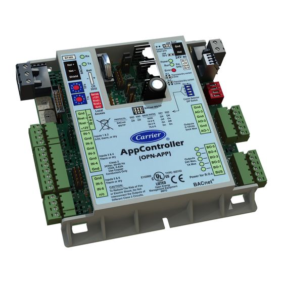
I/O connections. It has 5 binary outputs, 6 universal inputs, and 3 analog outputs. The AppController runs single purpose applications such as Fan Coil, Unit Vent, Air Source Interface, Water Source Heat Pump, and basic AHU AppController CARRIER CORPORATION ©2019 Installation and Start-up Guide All rights reserved... -
Page 8: Specifications
Battery-backed real time clock keeps track of time in the event of a power failure Battery 10-year Lithium CR2032 battery retains the following data for a maximum of 10,000 hours during power outages: control programs, graphics, editable properties, schedules, and trends. AppController CARRIER CORPORATION ©2019 Installation and Start-up Guide All rights reserved... -
Page 9: Safety Considerations
UL-916 (PAZX), cUL-916 (PAZX7), FCC Part 15-Subpart B-Class A, CE Safety considerations WARNING Disconnect electrical power to the AppController before wiring it. Failure to follow this warning could cause electrical shock, personal injury, or damage to the controller. AppController CARRIER CORPORATION ©2019 Installation and Start-up Guide All rights reserved... -
Page 10: Installing The Appcontroller
Screw the AppController into an enclosed panel using the mounting slots on the coverplate. Leave about 2 in. (5 cm) on each side of the controller for wiring. Mounting hole dimensions 5 9/16" (14.1 cm) between mounting slot center lines. AppController CARRIER CORPORATION ©2019 Installation and Start-up Guide All rights reserved... -
Page 11: Wiring The Appcontroller For Power
The AppController is powered by a Class 2 power source. Take appropriate isolation measures when mounting it in a control panel where non-Class 2 circuits are present. Carrier controllers can share a power supply as long as you: Maintain the same polarity. -
Page 12: Wiring For Communications
Check the communications wiring for shorts and grounds. Connect the communications wiring to the controller’s screw terminals labeled Net +, Net -, and Shield. NOTE Use the same polarity throughout the network segment. AppController CARRIER CORPORATION ©2019 Installation and Start-up Guide All rights reserved... -
Page 13: Wiring Inputs And Outputs
Pulse counter TLO 100 - 500 feet shielded ZS sensors See Wiring devices to the AppController's Rnet port (page 11). Wireless Adapter for wireless sensors Equipment Touch TruVu™ ET Display AppController CARRIER CORPORATION ©2019 Installation and Start-up Guide All rights reserved... -
Page 14: Inputs
The AppController has 3 analog outputs that support voltage. The controlled device must share the same ground as the controller and have the following input impedance: 0–10 Vdc Minimum impedance 2000 Ohms, max 5 mA NOTE Ohm's law: -10V/.005a = 2000 Ohms AppController CARRIER CORPORATION ©2019 Installation and Start-up Guide All rights reserved... -
Page 15: To Wire Inputs And Outputs
Connect the input wiring to the screw terminals on the AppController. NOTES Connect the shield wire to the GND terminal with the ground wire. ○ IN-5 and IN-6 share the GND terminal above IN-5. ○ AppController CARRIER CORPORATION ©2019 Installation and Start-up Guide All rights reserved... - Page 16 Set the Rnet jumper to Rnet. Wireless Adapter for wireless sensors Equipment Touch TruVu™ ET Display Connect the analog output wiring to the screw terminals on the AppController and to the controlled device. AppController CARRIER CORPORATION ©2019 Installation and Start-up Guide All rights reserved...
-
Page 17: Wiring Devices To The Appcontroller's Rnet Port
If shielded, Aluminum/Mylar shield (100% coverage) with TC drain wire, terminated at controller UL temperature rating 32–167°F (0–75°C) Voltage 300 Vac, power limited Listing UL: NEC CL2P, or better AppController CARRIER CORPORATION ©2019 Installation and Start-up Guide All rights reserved... -
Page 18: To Wire Zs Sensors To The Controller
.25 in. Inner insulation (.6 cm) Wire each terminal on the sensor to the same terminal on the controller. See diagram below. NOTE Carrier recommends that you use the following Rnet wiring scheme: Connect this wire... To this terminal... +12V... -
Page 19: To Wire The Wireless Adapter For Wireless Sensors
To wire the Wireless Adapter for wireless sensors WARNING Do not apply line voltage (mains voltage) to the Wireless Adapter. The Carrier wireless sensors are available in 868, 902, and 928 MHz radio frequency. The sensors are thermistor- based temperature sensors that may optionally sense humidity. - Page 20 Has a problem. Do one of the following: Cycle power to the device. Insert a small screwdriver or paper clip into the hole next to the LED to reboot the device. AppController CARRIER CORPORATION ©2019 Installation and Start-up Guide All rights reserved...
-
Page 21: To Wire An Equipment Touch To The Appcontroller
For complete Equipment Touch installation instructions including wiring diagrams, see the Equipment Touch Installation and Setup Guide. CAUTION The AppController can share a power supply with the Carrier controller as long as: The power supply is AC power. -
Page 22: To Wire The Truvu™ Et Display
Wire the TruVu™ ET Display 24V DC connector to the 24 Vdc power supply using 2-conductor 18 AWG wire. Maximum distance 100 feet (30 meters). CAUTION The TruVu™ ET Display can share a power supply with the Carrier controller as long as: ... -
Page 23: Installing The Appcontroller Into An I-Vu® Control System
Click Close. To upload a graphic, click Add New under Views and browse to your .view file. Click Continue. When message appears File added successfully, click Close. Click Close again. AppController CARRIER CORPORATION ©2019 Installation and Start-up Guide All rights reserved... -
Page 24: Local Access To The Appcontroller
If you are not sure of the wiring polarity, use a USB isolator between the computer and the USB Link. Purchase a USB isolator online from a third-party manufacturer. These are accessory items that do not come with the controller. AppController CARRIER CORPORATION ©2019 Installation and Start-up Guide All rights reserved... -
Page 25: Troubleshooting
Troubleshooting Troubleshooting If you have problems mounting, wiring, or addressing the AppController, contact Carrier Control Systems Support. NOTE To help you troubleshoot, obtain a Module Status (Modstat) from the controller and review the System Error and Warning details. LED's The LED’s indicate if the controller is speaking to the devices on the network. The LED’s should reflect communication traffic based on the baud rate set. -
Page 26: Serial Number
To restore defaults CAUTION This erases all archived information and user-configuration settings. You will have to reconfigure all custom settings. It is recommended to restore the factory defaults only under the guidance of Carrier Control Systems Support. To erase volatile memory data and restore factory default configuration settings: Turn off the AppController's power switch. -
Page 27: To Replace The Appcontroller's Battery
Remove the battery from the controller, making note of the battery's polarity. Insert the new battery, matching the battery's polarity with the polarity indicated on the AppController. AppController CARRIER CORPORATION ©2019 Installation and Start-up Guide All rights reserved... -
Page 28: Compliance
BACnet Compliance Compliance of listed products to requirements of ASHRAE Standard 135 is the responsibility of BACnet International. BTL ® is a registered trademark of BACnet International. AppController CARRIER CORPORATION ©2019 Installation and Start-up Guide All rights reserved... -
Page 29: Appendix A: Appcontroller Wire List
Type Channel code Name Name of Pins Number AO-1 AO-1 AO-2 AO-1 AO-3 AO-1 BO-1 N.O. BO-1 BO-2 N.O. BO-2 BO-3 N.O. BO-3 BO-4 N.O. BO-4 BO-5 N.O. BO-5 AppController CARRIER CORPORATION ©2019 Installation and Start-up Guide All rights reserved... -
Page 30: Appendix B: Ahu Cv (Small) Inputs And Outputs Points List
4 - Gnd Modulating HW Valve 0-10 Volt AO-3 6 - Gnd Modulating CW Valve 0-10 Volt Legend - Analog Input - Analog Output - Binary Input - Binary Output AppController CARRIER CORPORATION ©2019 Installation and Start-up Guide All rights reserved... -
Page 31: Document Revision History
Wiring for communications Changed from Wiring the AppController to the MS/TP network C-D-OC Specifications Added BACnet ARC156 connection and Wireless Adapter for C-D-OC Carrier wireless sensors. Corrected SPT information. Cover Changed to latest controller image. What is the AppController? 6/2/16 Specifications Corrected error. - Page 32 Document revision history AppController CARRIER CORPORATION ©2019 Installation and Start-up Guide All rights reserved...
- Page 33 CARRIER CORPORATION ©2019 A member of the United Technologies Corporation family · Stock symbol UTX · Catalog No. 11-808-477-01 · 1/23/2019...