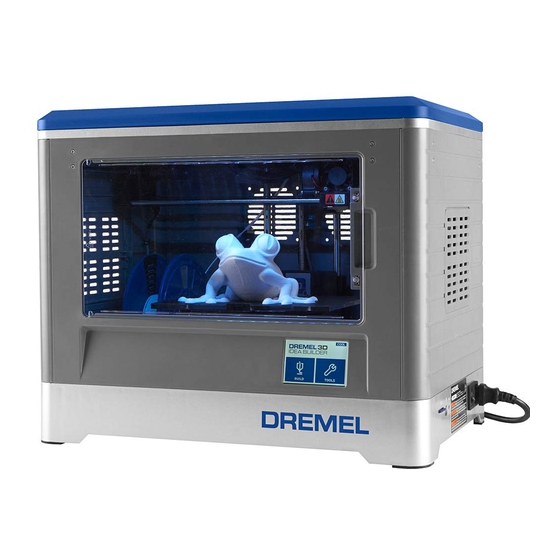
Dremel 3D20 Quick Start Manual
Nozzle replacement
Hide thumbs
Also See for 3D20:
- Original instructions manual (288 pages) ,
- Operating and safety instructions manual (108 pages) ,
- Quick start manual (8 pages)
Advertisement
Quick Links
Read the Dremel 3D20 manual and
these instructions. Failure to comply
with the warnings and instructions may result in fire,
equipment damage, property damage, or personal
Always unplug Dremel 3D20 from its power before per-
forming any service procedures. Failure to do so may
re-sult in personal injury and equipment damage.
Use only Dremel approved materials and components.
Use of object materials, or 3D objects other than Dremel
approved
object
materials
components may void warranty.
Repairs on the Dremel 3D20 may require the use of special
tools (pulling devices and bearing press). Authorized repair
centers have trained repair technicians and equipment
necessary to perform these repairs.
Do not touch the extruder tip or heated build platform during Dremel 3D20 operation or until it
has cooled down to at least 60oC (140oF). Contact with the extruder tip or build platform during or
after operation before tip and build platform has cooled may result in personal injury.
Tools Required:
• 2.5 mm Allen key
Step 1: Remove the top cover
Nozzle Replacement
injury.
and
genuine
Dremel
SERVICE INSTRUCTIONS
For the location of the repair center near you, look on
our web site at www.Dremel3D.com and follow the link
for 'Support'.
Step 2: Unload filament from the extruder.
Step 3: Power off then unplug the power
cord from the Dremel 3D Idea Builder.
Advertisement

Summary of Contents for Dremel 3D20
- Page 1 Do not touch the extruder tip or heated build platform during Dremel 3D20 operation or until it has cooled down to at least 60oC (140oF). Contact with the extruder tip or build platform during or after operation before tip and build platform has cooled may result in personal injury.
- Page 2 Step 4: Unplug the motor cable from Step 8: Move the turbo fan bracket and turbo fan away from the the stepper motor. extruder assembly. This will expose the wire connections. Step 5: Unscrew the fan baffle screw Step 9: Disconnect the from the left front side of the extruder assembly.
- Page 3 Step 16: Insert and tighten both Step 12: All wires should be screws, left and right, to secure disconnected. Move the turbo fan extruder assembly to the extruder and bracket out of the way. carriage. Step 13: Unscrew the extruder Step 17: Reconnect the fan wire mounting screws from underneath connector.
- Page 4 Step 24: Insert and tighten the fan baffle screw Step 20: With all wires connected, neatly on the front left side of the extruder assembly. place the connectors into the open area of the turbo fan bracket. Make sure wires lay flat underneath the stepper motor.


