
Related Manuals for Ariston Nuos Split Flex 150L


Summary of Contents for Ariston Nuos Split Flex 150L
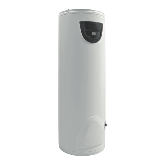
- Page 1 Heat pump water heater Scaldacqua a pompa di calore Warmtepompboiler Wärmepumpen Heißwasserbereiter...
- Page 3 Cher Client, Nous vous remercions d’avoir préféré notre chauffe-eau thermodynamique lors de votre achat. Nous souhaitons qu’il puisse satisfaire toutes vos attentes et vous fournisse pendant de nombreuses années les meilleurs services et le maximum d’économies d’énergie. Notre groupe dédie en effet beaucoup de temps, d’énergie et ressources économiques à la réalisation d’innovations, qui favorisent les économies d’énergie de nos produits.
-
Page 4: Table Of Contents
SOMMAIRE RECOMMANDATIONS DE SÉCURITÉ INFORMATIONS GENERALES AVERTISSEMENTS GENERAUX Signification des symboles utilisés Champ d’application Prescription et normes techniques Certifications du produit Emballage et accessoires fournis Transport et déplacements Identification de l’appareil CARACTERISTIQUES TECHNIQUES Principe de fonctionnement Schéma de composants unité intérieure Schéma de composants unité... -
Page 5: Recommandations De Sécurité
Chauffe-eau thermodynamique – RECOMMANDATIONS DE SÉCURITÉ RECOMMANDATIONS DE SÉCURITÉ ATTENTION! 1. Le présent livret constitue une partie intégrante et essentielle du produit. Il doit être conservé soigneusement et devra toujours accompagner l'appareil même en cas de cession à un autre propriétaire ou utilisateur et/ou de transfert sur une autre installation. - Page 6 Chauffe-eau thermodynamique – RECOMMANDATIONS DE SÉCURITÉ originales. Le non respect de ce qui est indiqué plus haut peut compromettre la sécurité et fait déchoir la responsabilité du fabricant. 10. La température de l'eau chaude est réglée par un thermostat de fonctionnement qui sert également de dispositif de sécurité...
-
Page 7: Informations Generales
chauffe-eau thermodynamique – NOTICES TECHNIQUES POUR L'INSTALLATEUR INFORMATIONS GENERALES 1.1 Signification des symboles utilisés En ce qui concerne les aspects liés à la sécurité d’installation, et d’utilisation, des symboles ont été utilisés pour mettre en évidence les avertissements des risques. Leur signification est expliquée dans le tableau suivant. Symbole Signification Le non respect de l’avertissement entraîne des risques de lésions, et des risques mortels dans... -
Page 8: Certifications Du Produit
chauffe-eau thermodynamique – NOTICES TECHNIQUES POUR L'INSTALLATEUR 1.4 Certifications du produit Le marquage CE présent sur l'appareil atteste sa conformité aux Directives Communautaires suivantes, dont il répond aux exigences essentielles : - 2014/35/EU relative à la sécurité électrique (EN/IEC 60335-1; EN/IEC 60335-2-21; EN/IEC 60335-2-40); - 2014/30/EU relative à... -
Page 9: Identification De L'appareil
chauffe-eau thermodynamique – NOTICES TECHNIQUES POUR L'INSTALLATEUR 1.7 Identification de l’appareil Les principales informations d’identification de l’appareil sont indiquées sur la plaque signalétique collée sur le corps du chauffe-eau. Plaque signalétique unité intérieur Description A Modèle B litrage cuve C N° de série tension d’alimentation, fréquence, puissance maximale absorbée E pression maximum/minimum circuit réfrigérant... -
Page 10: Schéma De Composants Unité Intérieure
chauffe-eau thermodynamique – NOTICES TECHNIQUES POUR L'INSTALLATEUR 2.2 Schéma de composants unité intérieur FIG.1 MODÉLE 150 L MODÉLE 200 L 1050 Référence fig. 1& 2 en fin de livret 1200 1520 Raccord 3/4'’ sortie eau chaude Raccord 3/4’’ entrée eau froide Raccordement gaz type flare 3/8 “... -
Page 11: Caractéristiques Techniques
chauffe-eau thermodynamique – NOTICES TECHNIQUES POUR L'INSTALLATEUR 2.5 Caractéristiques techniques Description Unité 150 L 200 L 270 L UNITÉ INTÉRIEURE Capacité nominale du réservoir Epaisseur de l’ isolant ≈ 55 ≈ 55 ≈ 50 Type de protection de la cuve Émaillée Anode titane à... - Page 12 chauffe-eau thermodynamique – NOTICES TECHNIQUES POUR L'INSTALLATEUR Dénivelé maxi raccordement fluide frigorigène (Unité externe au dessus de l'unité intérieure) Dénivelé maxi raccordement fluide frigorigène (Unité externe sous l'unité intérieure) Fluide frigorigène R134a 1400 Quantité de gaz à effet de serre fluorés tonnes équivalent CO 2,002 Potentiel de réchauffement planétaire...
-
Page 13: Avertissements
chauffe-eau thermodynamique – NOTICES TECHNIQUES POUR L'INSTALLATEUR Plus données énergétiques sont présentés dans le tableau du produit (annexe A), qui fait partie intégrante de ce livret. Les produits sans étiquette et l'onglet relatif pour les ensembles de chauffe-eau solaires et appareils, prévus par le règlement 812/2013, ne sont pas destinés à... -
Page 14: Installation
chauffe-eau thermodynamique – NOTICES TECHNIQUES POUR L'INSTALLATEUR S’assurer que les échelles ou escabeaux soient stables, solides, que les marches ou échelons soient en bon état et solidement Lésion par chute ou par cisaillement. fixés. Tout travail en hauteur doit être effectué sous la surveillance d’une tierce personne. -
Page 15: Emplacement Unité Extérieure
chauffe-eau thermodynamique – NOTICES TECHNIQUES POUR L'INSTALLATEUR Respecter les distances minimales d'installation de la figure 5 ; Eviter d’installer l’appareil dans des endroits où il peut y avoir formation de gel. Les performances et la sécurité du produit ne sont pas garanties dans le cas d’installation de l’unité intérieure à l’extérieur ; le lieu d’installation et les installations électriques et hydrauliques sont conformes aux normes en vigueur ;... -
Page 16: Connexions À L'unité Intérieure
chauffe-eau thermodynamique – NOTICES TECHNIQUES POUR L'INSTALLATEUR Détecteur de fuites pour R134a, utilisant un détecteur unique pour les réfrigérants HFC. Il doit avoir une grande sensibilité de détection, 5 g/année minimum. 4.5 Préparation des liaisons frigorifiques ATTENTION! Avant toute installation vérifiez les points suivants: Utilisez des tubes en cuivre pour les climatiseurs ou des tubes de type ACR (air conditionné, réfrigération) en cuivre avec une isolation adéquate (au moins 6 mm d'épaisseur), adapté... -
Page 17: Charge De Gaz Réfrigérant
chauffe-eau thermodynamique – NOTICES TECHNIQUES POUR L'INSTALLATEUR Après avoir ouvert les soupapes nécessaires de la pompe (B), mettez-la en marche et faites-la fonctionner. Créez le vide pendant environ 20/25 minutes. Vérifiez si le manomètre de basse pression (A) indique une pression égale à -1bar (ou -76 cm Hg) ; Fermez les robinets de la pompe et arrêtez-la (B). -
Page 18: Raccordement Électrique
chauffe-eau thermodynamique – NOTICES TECHNIQUES POUR L'INSTALLATEUR déconseillés (tuyaux en PER particulièrement). Il faut obligatoirement poser le raccord diélectrique (fourni avec le produit) sur le tube de sortie de l’eau chaude avant d’effectuer la connexion. Visser sur le tube d’entrée d’eau de l’appareil, indiqué par un collier de couleur bleu, un raccord en forme de “T”. Sur ce raccord, visser sur un côté... -
Page 19: Premiére Mise En Service
chauffe-eau thermodynamique – NOTICES TECHNIQUES POUR L'INSTALLATEUR Le câble d'alimentation n'est pas fourni avec le produit. Il est conseillé d’effectuer un contrôle de l’installation électrique en vérifiant la conformité aux normes en vigueur. Vérifier que l’installation soit adaptée pour la puissance maximale absorbée par le chauffe-eau (voir les données sur la plaque signalétique), aussi bien pour ce qui est de la section des conducteurs que pour leur conformité... -
Page 20: Instructions D'utilisation Et D'entretien Pour L'utilisateur
Chauffe-eau thermodynamique – INSTRUCTIONS D'UTILISATION ET D’ENTRETIEN POUR L'UTILISATEUR INSTRUCTIONS D'UTILISATION ET D’ENTRETIEN POUR L'UTILISATEUR 6. AVERTISSEMENTS 6.1 Première mise en service ATTENTION! L’installation et la première mise en service de l’appareil doivent être faites par des professionnels qualifiés, en conformité avec les normes nationales d’installation en vigueur et selon les éventuelles prescriptions des autorités locales et d’organismes de santé... -
Page 21: Recommandations Pour Empêcher La Prolifération De La Légionellose
Chauffe-eau thermodynamique – INSTRUCTIONS D'UTILISATION ET D’ENTRETIEN POUR L'UTILISATEUR Ne pas ouvrir l’appareil Lésions par électrocution ou brûlure ou coupure. Ne pas tirer sur le(s) câble(s) Lésions par électrocution suite à un contact avec d’alimentation de l’appareil des câbles sous tension dénudés. Ne pas utiliser d’échelle, d’escabeau ou de chaise instable pour effectuer le nettoyage Lésions par chute ou par cisaillement. -
Page 22: Instructions De Fonctionnement
Chauffe-eau thermodynamique – INSTRUCTIONS D'UTILISATION ET D’ENTRETIEN POUR L'UTILISATEUR 1) l'appareil est éteint pendant un certain temps [des mois] ou 2) la température de l'eau est maintenue constamment entre 25°C et 50°C, les bactéries de la Légionellose pourraient se développer à l'intérieur du réservoir. Dans ces cas, pour réduire la prolifération de la légionellose, il est nécessaire d'avoir recours au «... -
Page 23: Comment Allumer Et Éteindre Le Chauffe-Eau
Chauffe-eau thermodynamique – INSTRUCTIONS D'UTILISATION ET D’ENTRETIEN POUR L'UTILISATEUR 7.2 Comment allumer et éteindre le chauffe-eau Allumage: pour allumer le chauffe-eau il suffit d’appuyer sur le bouton ON/OFF L’écran montre la température réglée “set”, le mode de fonctionnement, le symbole HP et/ou le symbole de la résistance indiquent le fonctionnement de la pompe à... -
Page 24: Réglage De L'heure
Chauffe-eau thermodynamique – INSTRUCTIONS D'UTILISATION ET D’ENTRETIEN POUR L'UTILISATEUR régler l'heure à laquelle l’eau chaude doit être disponible et appuyez sur le bouton/molette pour confirmer. Si vous souhaitez utiliser le mode P1 + P2, vous devez définir les informations pour les deux programmes. Afin d’utiliser ce mode, vous devez régler l’heure comme indiqué... -
Page 25: Menu Installateur
Chauffe-eau thermodynamique – INSTRUCTIONS D'UTILISATION ET D’ENTRETIEN POUR L'UTILISATEUR ANTI_B Activation/désactivation de la fonction Anti légionnelle (on/off) T HP Température maximum réglée grâce à la pompe à chaleur T W1 Température relevée sonde 1 résistance T W2 Température relevée sonde 2 résistance Température relevée sonde tube eau chaude T AIR Température relevée sonde air d’entrée... -
Page 26: Vérification Des Connexions Électriques, "Check
Chauffe-eau thermodynamique – INSTRUCTIONS D'UTILISATION ET D’ENTRETIEN POUR L'UTILISATEUR PROG Activation / désactivation du mode “PROGRAM” : P1, P2, P1+P2 (on/off). BOOST2 Activation/désactivation de la fonction Boost2 (on/off) Activation/déactivation de la fonction Auto (on/off) AUTO Voir paragraphe 7.4 Réglage de l'hystérésis du compresseur (3-12 ° C). L'hystérésis est la différence de HYST température du thermostat. -
Page 27: Réglages D'usine
Chauffe-eau thermodynamique – INSTRUCTIONS D'UTILISATION ET D’ENTRETIEN POUR L'UTILISATEUR 7.10 Réglages d’usine Le chauffe-eau est livré d'usine selon la configuration ci-dessous. Paramètre Etat réglage d’usine MODE GREEN ACTIVE MODE BOOST ACTIVE TEMPERATURE PREREGLEE 50 °C TEMP. MAXI REGL. RESISTANCE 65 °C TEMP. -
Page 28: Vidange De L'appareil
Chauffe-eau thermodynamique – INSTRUCTIONS D'UTILISATION ET D’ENTRETIEN POUR L'UTILISATEUR les sondes, tube eau chaude et résistance Vérifier le bon fonctionnement ou éventuellement changer la vanne 4 voies. Vérifiez que le Pression faible dans le circuit ventilateur ne soit pas en panne (dans le cas le réfrigérant, ou problème remplacer). -
Page 29: Entretien Périodique
Chauffe-eau thermodynamique – INSTRUCTIONS D'UTILISATION ET D’ENTRETIEN POUR L'UTILISATEUR 8.2 Entretien périodique Il est conseillé d’effectuer tous les ans le nettoyage de l’évaporateur pour enlever la poussière ou les obstructions. Pour accéder à l'évaporateur, situé sur l'unité extérieure, retirez les vis retenant la grille. Nettoyer l'évaporateur avec une brosse flexible en prenant soin de ne pas l'endommager. -
Page 30: Entretien Ordinaire Réservé À L'utilisateur
Chauffe-eau thermodynamique – INSTRUCTIONS D'UTILISATION ET D’ENTRETIEN POUR L'UTILISATEUR Dommages ou déconnexion des câbles reliant la Vérifier l’intégrité de la connexion, vérifier le fonctionnement Problèmes pour carte électronique et la carte d’interface des cartes électroniques afficher l’écran ou désactiver Vérifiez la présence et l’état de l’alimentation et des batteries, absence d’... - Page 31 Dear Customer: We wish to thank you for having purchased the heat pump water heater. We hope that it meets your expectations and may offer you optimal service coupled with maximum energy saving for many years to come. Our group invests a lot of time, energy and economic resources in creating innovative solutions aimed at reducing the energy consumption of its products.
- Page 32 TABLE OF CONTENTS SAFETY INFORMATION GENERAL INFORMATION. GENERAL INFORMATION Description of the symbols used Field of application Instructions and technical norms Product certifications Packaging and supplied accessories Transport and handling Identification of the appliance TECHNICAL FEATURES Operating principle Internal unit construction features External unit construction features Electrical diagram Technical data table...
-
Page 33: Safety Warnings
Heat pump water heater – SAFETY WARNINGS SAFETY WARNINGS CAUTION 1. This manual is an integral part of the product. Keep it with care with the appliance, and hand it on to the next user/owner in case of change of property. - Page 34 Heat pump water heater – SAFETY WARNINGS compliant with said standard; it must be calibrated to a maximum pressure of 0.7 MPa, including at least a cock, check valve, safety valve and hydraulic load cut-out. 14. It is normal that water drips from the overpressure safety device or from the EN 1487 safety unit when the appliance is heating.
-
Page 35: General Information
Heat pump water heater – TECHNICAL INFORMATION FOR INSTALLERS GENERAL INFORMATION 1.1 Description of the symbols used In terms of installation and operation safety, the symbols described in the table below are used in order to stress the importance of the relative risk warnings: Symbol Description Failure to comply with this warning may result in injury to persons or, in some cases, death. -
Page 36: Product Certifications
Heat pump water heater – TECHNICAL INFORMATION FOR INSTALLERS 1.4 Product certifications The CE marking of the appliances attests its conformity to the following EC Directives, of which it satisfies the essential requisites: - 2014/35/EU on electrical safety (EN/IEC 60335-1; EN/IEC 60335-2-21; EN/IEC 60335-2-40); - 2014/30/EU on electromagnetic compatibility (EN 55014-1;... -
Page 37: Identification Of The Appliance
Heat pump water heater – TECHNICAL INFORMATION FOR INSTALLERS 1.7 Identification of the appliance The main information for identifying the appliance is contained on the adhesive data plate located on the water heater casing. Internal unit 35isuali label Description A model B tank capacity C serial no. -
Page 38: Internal Unit Construction Features
Heat pump water heater – TECHNICAL INFORMATION FOR INSTALLERS 2.2 Internal unit construction features FIG.1 MODEL 150 LITRES MODEL 200 LITRES 1050 fig. 1-2. 1200 1520 Outlet hot water 3/4” pipe Inlet cold water 3/4” pipe Outlet gas pipe 3/8 “ Inlet gas pipe 1/4 “... -
Page 39: Technical Data Table
Heat pump water heater – TECHNICAL INFORMATION FOR INSTALLERS 2.5 Technical data table Unit of Description 150 L 200 L 270 L measurement INTERNAL UNIT Rated tank capacity Insulation thickness ≈ 55 ≈ 55 ≈ 50 Type of internal tank protection enamelling titanium impressed current anode + disposable Type of corrosion protection... - Page 40 Heat pump water heater – TECHNICAL INFORMATION FOR INSTALLERS Maximum height difference between external unit and refrigerant gas pipe connections (external unit under external unit) Quantity of R134a refrigerant fluid 1400 tonnes CO Quantity of fluorinated greenhouse gases 2,002 equivalent Global warming potential 1430 Max.
-
Page 41: Warnings
Heat pump water heater – TECHNICAL INFORMATION FOR INSTALLERS Products which do not have the label and data sheet required for boiler/solar power configurations pursuant to regulation 812/2013 may not be used in such installations. TECHNICAL INFORMATION FOR INSTALLERS 3. WARNINGS 3.1 Installer qualification WARNING! The installation and initial start-up of the appliance must be performed by qualified personnel in compliance with the national regulations in force regarding installation, and in conformity with any regulations... -
Page 42: Installation
Heat pump water heater – TECHNICAL INFORMATION FOR INSTALLERS Make sure that any portable ladders are securely positioned, that they are sufficiently resistant, that the steps are intact and not slippery, that Personal injury caused by falling from a height or these do not move around when someone cuts (stepladders shutting accidentally). -
Page 43: Location Of The External Unit
Heat pump water heater – TECHNICAL INFORMATION FOR INSTALLERS Ensure that the installation site and the electrical and hydraulic systems to which the appliance must be connected fully comply with the regulations in force. The chosen site must have, or must be suitable to house, a single-phase 220-230 V ~ 50 Hz power supply socket. -
Page 44: Preparing Of The Refrigerating Pipes
Heat pump water heater – TECHNICAL INFORMATION FOR INSTALLERS Pipe reamer; g) Leak Detector for R134a, a leak detector is used exclusively for HFC refrigerants. It must have a high detection sensitivity, minimum 5g per year. 4.5 Preparing of the refrigerating pipes WARNING! Before carrying out any installation check the following: a) Use only copper tubes for air conditioners type (copper tubing for the refrigeration and the conditioning) or copper pipes with proper insulation (at least 6 mm thick), suitable for use with R134a;... -
Page 45: Making The Vacuum, The Connection And Check The Seal
Heat pump water heater – TECHNICAL INFORMATION FOR INSTALLERS 4.8 Making the vacuum, the connection and check the seal (see fig 11). Bleeding from the circuit should take place with a vacuum pump and pressure gauge assembly suitable for R134a. Make sure the vacuum pump is full of oil up to the level indicated by the oil gauge. -
Page 46: Hydraulic Connections
Heat pump water heater – TECHNICAL INFORMATION FOR INSTALLERS 4.10 Hydraulic connections Before using the product, we recommend filling its tank with water and draining it completely so as to remove the residual impurities. Connect the water heater inlet and outlet to pipes or pipe fittings that can withstand the operating pressure and temperature of the hot water, which may reach 75 °C. -
Page 47: Initial Start Up
Heat pump water heater – TECHNICAL INFORMATION FOR INSTALLERS WARNING: BEFORE YOU GET ACCESS TO TERMINALS, ALL SUPPLY CIRCUITS MUST BE DISCONNECTED It is advisable to carry out a check on the electrical system to verify conformity to the regulations in force. Verify that the electrical system can suitably withstand the water heater’s maximum power consumption values (refer to the data plate), in terms of the size of the cables and their conformity to the regulations in force. -
Page 48: Warnings
Heat pump water heater – OPERATING AND MAINTENANCE INSTRUCTIONS OPERATING AND MAINTENANCE INSTRUCTIONS 6. WARNINGS 6.1 Initial start-up WARNING! The installation and initial start-up of the appliance must be performed by qualified personnel in compliance with the national regulations in force regarding installation, and in conformity with any regulations issued by local authorities and public health bodies. -
Page 49: Recommendations For Prevention Of Legionella Growth
Heat pump water heater – OPERATING AND MAINTENANCE INSTRUCTIONS Damage to the appliance or any underlying objects caused by the appliance detaching from its fixing brackets and falling. Electrocution due to exposure to live components. Do not perform any operations that Personal injury caused by burns due to overheated involve opening the appliance. -
Page 50: Instructions For Use
Heat pump water heater – OPERATING AND MAINTENANCE INSTRUCTIONS nutrients, biofilm and sediment within the installation including water heaters, etc. Sediment can support the growth of Legionella bacteria and it should be removed on a regular basis from e.g. storage systems, water heaters, non- flown through expansion vessels (e.g. -
Page 51: Turning The Water Heater On/Off
Heat pump water heater – OPERATING AND MAINTENANCE INSTRUCTIONS 7.2 Turning the water heater on/off Turning the appliance on: simply press the ON/OFF button to turn the water heater The DISPLAY 49isualize49 the “set” temperature and operation mode, while the HP symbol and/or heating element symbol indicate the operation of the heat pump and/or heating element respectively. -
Page 52: Time Setting
Heat pump water heater – OPERATING AND MAINTENANCE INSTRUCTIONS Note: To ensure comfort, in the case of P1 + P2 mode operation with very close times between them, it is possible that the temperature of water is higher than the temperature set, in which case it may appear the symbol of the waves. -
Page 53: Installer Menu
Heat pump water heater – OPERATING AND MAINTENANCE INSTRUCTIONS T EVAP Temperature recorded by the evaporator sensor. DEFROS Activated/deactivated status of the defrost function (on/off). HP h Meter for internal parameter 1. HE h Meter for internal parameter 2. SW MB Mainboard software version. -
Page 54: Electrical Connections "Check
Heat pump water heater – OPERATING AND MAINTENANCE INSTRUCTIONS CHARG Activation of the cycle inversion procedure, to allow the gas charging (see paragraph 4.9) (activate this only in presence of mains alimentation). 7.8 Electrical connections "Check" (function activated by the installer menu) With this function you can control the electrical connections made during installation. -
Page 55: Anti-Frost Function
Heat pump water heater – OPERATING AND MAINTENANCE INSTRUCTIONS To be able to operate also on appliances with a two-tier rate system, the control logic calculates the number of average hours a day during which the power supply is available in the economy mode (HC). A self-learning function ensures that the appliance reaches the pre-set temperature in the time range during which the economy rate applies;... -
Page 56: Draining The Appliance
Heat pump water heater – OPERATING AND MAINTENANCE INSTRUCTIONS Empty tank (EMPTY), impressed Verify whether there is any water in the tank, check or current anode circuit open replace the impressed current anode, if necessary. Short-circuit on the impressed Check or replace the impressed current anode if current anode circuit necessary 8. -
Page 57: Routine Maintenance Performed By Users
Heat pump water heater – OPERATING AND MAINTENANCE INSTRUCTIONS electrical Problems with the heat pump circuit Make sure that there are no errors on the display resistance Are not yet past 8 days by: -First Time instalation. -change of the parameter Time-W. -No power from mains in absence of batteries or exhausted batteries. - Page 58 Gentile Cliente, desideriamo ringraziarla per aver preferito nel Suo acquisto il nostro scaldacqua a pompa di calore. Ci auguriamo che esso soddisfi le Sue aspettative e possa fornire per molti anni il miglior servizio ed il massimo risparmio energetico. Il nostro gruppo dedica infatti molto tempo, energie e risorse economiche alla realizzazione di soluzioni innovative che favoriscano il risparmio energetico nei propri prodotti.
- Page 59 INDICE AVVERTENZE DI SICUREZZA INFORMAZIONI GENERALI INFORMAZIONI GENERALI Significato dei simboli utilizzati Campo d'impiego Prescrizioni e norme tecniche Certificazioni di prodotto Imballaggio e accessori forniti Trasporto e movimentazione Identificazione dell’apparecchio CARATTERISTICHE TECNICHE Principio di funzionamento Caratteristiche costruttive e dimensioni unità interna Caratteristiche costruttive e dimensioni unità...
- Page 60 Scaldacqua a pompa di calore – AVVERTENZE DI SICUREZZA AVVERTENZE DI SICUREZZA ATTENZIONE! 1. Il presente libretto costituisce parte integrante ed essenziale del prodotto. Va conservato con cura e dovrà sempre accompagnare l’apparecchio anche in caso di sua cessione ad altro proprietario o utente e/o di trasferimento su altro impianto.
- Page 61 Scaldacqua a pompa di calore – AVVERTENZE DI SICUREZZA 10. La temperatura dell’acqua calda è regolata da un termostato di funzionamento che funge anche da dispositivo di sicurezza riarmabile per evitare pericolosi incrementi di temperatura. 11. La connessione elettrica deve essere realizzata come indicato nel relativo paragrafo.
- Page 62 Scaldacqua a pompa di calore – ISTRUZIONI D'USO E MANUTENZIONE PER L’UTENTE INFORMAZIONI GENERALI 1.1 Significato dei simboli utilizzati Relativamente agli aspetti legati alla sicurezza nell’installazione e nell’uso, per meglio evidenziare le avvertenze sui relativi rischi, vengono utilizzati alcuni simboli il cui significato viene esplicitato nella seguente tabella. Simbolo Significato Il mancato rispetto dell’avvertenza comporta rischio di lesioni, in determinate circostanze anche...
- Page 63 Scaldacqua a pompa di calore – ISTRUZIONI D'USO E MANUTENZIONE PER L’UTENTE 1.4 Certificazioni di prodotto L’apposizione della marcatura CE sull’apparecchio ne attesta la conformità alle seguenti Direttive Comunitarie, di cui soddisfa i requisiti essenziali: - 2014/35/EU relativa alla sicurezza elettrica (EN/IEC 60335-1; EN/IEC 60335-2-21; EN/IEC 60335-2-40); - 2014/30/EU relativa alla compatibilità...
- Page 64 Scaldacqua a pompa di calore – ISTRUZIONI D'USO E MANUTENZIONE PER L’UTENTE 1.7 Identificazione dell’apparecchio Le principali informazioni per l’identificazione dell’apparecchio sono riportate nell’apposita targa adesiva applicata sulla carrozzeria dell’unità interna e sull’unità esterna. Targhetta unità interna Descrizione A modello B litraggio serbatoio C nr.
- Page 65 Scaldacqua a pompa di calore – ISTRUZIONI D'USO E MANUTENZIONE PER L’UTENTE 2.2 Caratteristiche costruttive FIG.1 MODELLO 150 LITRI MODELLO 200 LITRI e dimensioni unità interna 1050 Riferimento fig. 1-2. 1200 1520 Tubo 3/4” acqua calda in uscita Tubo 3/4” acqua fredda in ingresso Bocchettone gas 3/8 “...
- Page 66 Scaldacqua a pompa di calore – ISTRUZIONI D'USO E MANUTENZIONE PER L’UTENTE 2.5 Tabella dati tecnici Descrizione Unità 150 L 200 L 270L UNITÁ INTERNA Capacità nominale serbatoio Spessore isolamento ≈ 55 ≈ 55 ≈ 50 Tipo di protezione interna smaltatura anodo titanio a corrente impressa + anodo Tipo di protezione dalla corrosione...
- Page 67 Scaldacqua a pompa di calore – ISTRUZIONI D'USO E MANUTENZIONE PER L’UTENTE Dislivello massimo unità esterna rispetto raccordi fluido refrigerante (unità esterna sotto unità interna) Quantità di fluido refrigerante R134a 1400 Quantità di gas fluorurati tonn. CO 2,002 Potenziale di riscaldamento globale 1430 Temperatura max acqua con pompa di calore °C...
- Page 68 Scaldacqua a pompa di calore – ISTRUZIONI D'USO E MANUTENZIONE PER L’UTENTE NOTIZIE TECNICHE PER L'INSTALLATORE 3. AVVERTENZE 3.1 Qualificazione dell’installatore ATTENZIONE! L’installazione e la prima messa in servizio dell’apparecchio devono essere effettuate da personale professionalmente qualificato, in conformità alle normative nazionali di installazione in vigore e ad eventuali prescrizioni delle autorità...
- Page 69 Scaldacqua a pompa di calore – ISTRUZIONI D'USO E MANUTENZIONE PER L’UTENTE Assicurarsi che le scale portatili siano stabilmente appoggiate, che siano resistenti, che i gradini siano Lesioni personali per la caduta dall’alto integri e non scivolosi, che non vengano spostate o per cesoiamento (scale doppie).
- Page 70 Scaldacqua a pompa di calore – ISTRUZIONI D'USO E MANUTENZIONE PER L’UTENTE Rispettare le dimensioni minime di installazione indicate in figura 5, Evitare di installare l’apparecchio in ambienti in cui si possano raggiungere condizioni che favoriscano la formazione di ghiaccio. Il prodotto è stato progettato per installazioni interne, non sono garantite le prestazioni e la sicurezza del prodotto qualora venga installato all’esterno;...
- Page 71 Scaldacqua a pompa di calore – ISTRUZIONI D'USO E MANUTENZIONE PER L’UTENTE Cartellatrice a pinza per ø nominali di 1/4 ” e 3/8”, dotata di un morsetto con foro ricevitore in modo che la proiezione del tubo di rame possa essere regolata a 0-0,5 mm, nella lavorazione della cartella; Taglia tubi;...
- Page 72 Scaldacqua a pompa di calore – ISTRUZIONI D'USO E MANUTENZIONE PER L’UTENTE Rimuovere la copertura in plastica dell’alloggiamento connessioni gas, avvitare i bocchettoni agli attacchi dell’unità esterna con lo stesso serraggio descritto per l’unità interna. 4.8 Fare il vuoto, la connessione e verificare la tenuta (vedere fig. 11) Lo spurgo dell’aria dal circuito deve avvenire per mezzo di una pompa per il vuoto e il gruppo manometri adatti all’...
- Page 73 Scaldacqua a pompa di calore – ISTRUZIONI D'USO E MANUTENZIONE PER L’UTENTE calore e con il cercafughe verificare che non ci siano Una volta terminato il tempo a disposizione per la perdite di refrigerante; funzione “Charge”, verificare corretto Staccare il contenitore dal manometro e richiudere funzionamento dell’apparecchio.
- Page 74 Scaldacqua a pompa di calore – ISTRUZIONI D'USO E MANUTENZIONE PER L’UTENTE Segnale EDF cavo non fornito con l’apparecchio 2G min. 0.5mm H05VV-F Cavo alimentazione unità esterna cavo non fornito con l’apparecchio 5G 0.75÷1.5 mm H05RN-F Cavo collegamento sonde unità cavo fornito con l’apparecchio schermato - UL2464 interna-unità...
- Page 75 Scaldacqua a pompa di calore – ISTRUZIONI D'USO E MANUTENZIONE PER L’UTENTE ISTRUZIONI D'USO E MANUTENZIONE PER L’UTENTE 6. AVVERTENZE 6.1 Prima messa in servizio ATTENZIONE! L’installazione e la prima messa in servizio dell’apparecchio devono essere effettuate da personale professionalmente qualificato, in conformità alle normative nazionali di installazione in vigore e ad eventuali prescrizioni delle autorità...
- Page 76 Scaldacqua a pompa di calore – ISTRUZIONI D'USO E MANUTENZIONE PER L’UTENTE Folgorazione per presenza di componenti sotto tensione. Non effettuare operazioni che implichino Lesioni personali per ustioni per presenza di componenti l’apertura dell’apparecchio. surriscaldati o per ferite per presenza di bordi e protuberanze taglienti.
- Page 77 Scaldacqua a pompa di calore – ISTRUZIONI D'USO E MANUTENZIONE PER L’UTENTE il batterio della Legionella potrebbe crescere all'interno del serbatoio. In questi casi, per ridurre la proliferazione della Legionella, è necessario ricorrere al cosiddetto "ciclo di sanificazione termica". Lo scaldacqua ad accumulo di tipo elettromeccanico viene venduto con un termostato impostato ad una temperatura superiore a 60 °C, ciò...
- Page 78 Scaldacqua a pompa di calore – ISTRUZIONI D'USO E MANUTENZIONE PER L’UTENTE 7.2 Come accendere e spegnere lo scaldacqua Accensione: per accendere lo scaldacqua è sufficiente premere il tasto ON/OFF. Il DISPLAY mostra la temperatura impostata “set”, la modalità di funzionamento, e il simbolo HP e/o il simbolo della resistenza indicano il relativo funzionamento della pompa di calore e/o della resistenza.
- Page 79 Scaldacqua a pompa di calore – ISTRUZIONI D'USO E MANUTENZIONE PER L’UTENTE Nel caso di collegamento elettrico con tariffa bioraria con segnale HC/HP, è comunque possibile programmare il riscaldamento dell’acqua in qualsiasi orario della giornata. Per questa funzione è richiesta l’impostazione dell’orario corrente, vedere paragrafo successivo. Avvertenza: per garantire il comfort, nel caso di funzionamento in modalità...
- Page 80 Scaldacqua a pompa di calore – ISTRUZIONI D'USO E MANUTENZIONE PER L’UTENTE T W1 Temperatura rilevata sonda 1 gruppo resistenza T W2 Temperatura rilevata sonda 2 gruppo resistenza Temperatura rilevata sonda acqua calda T AIR Temperatura rilevata sonda aria ingresso T EVAP Temperatura rilevata sonda evaporatore DEFROS...
- Page 81 Scaldacqua a pompa di calore – ISTRUZIONI D'USO E MANUTENZIONE PER L’UTENTE PROG Attivazione/disattivazione della funzione Program: P1, P2, P1+P2 (on/off). BOOST2 Attivazione/disattivazione della funzione Boost2 (on/off). Attivazione/disattivazione della funzione Auto (on/off). AUTO Vedere paragrafo 7.4 Regolazione dell’isteresi del compressore (3-12°C). L’isteresi è il delta temperatura off/on del termostato.
- Page 82 Scaldacqua a pompa di calore – ISTRUZIONI D'USO E MANUTENZIONE PER L’UTENTE HC-HP (funzionamento con tariffa bi-oraria) DISATTIVATA TIME_W (numero di ore di alimentazione accettato) MODALITÁ PROGRAM (P1, P2, P1+P2) DISATTIVATA TEMPERATURA IMPOSTATA PROGRAMMA P1 55°C ORARIO IMPOSTATO PROGRAMMA P1 06:00 TEMPERATURA IMPOSTATA PROGRAMMA P2 55°C...
- Page 83 Scaldacqua a pompa di calore – ISTRUZIONI D'USO E MANUTENZIONE PER L’UTENTE far verificare il cablaggio di collegamento con le schede elettroniche. Controllare sonda evaporatore. Controllare il corretto collegamento del cablaggio sonde tra Errore sonda aria le unità interna ed esterna, far verificare il posizionamento ed eventualmente sostituire la sonda Controllare il corretto collegamento del cablaggio sonde tra Errore sonda evaporatore...
- Page 84 Scaldacqua a pompa di calore – ISTRUZIONI D'USO E MANUTENZIONE PER L’UTENTE A seguito di un intervento di manutenzione ordinaria o straordinaria, è opportuno riempire con acqua il serbatoio dell’apparecchio ed effettuare una successiva operazione di completo svuotamento, al fine di rimuovere eventuali impurità...
- Page 85 Scaldacqua a pompa di calore – ISTRUZIONI D'USO E MANUTENZIONE PER L’UTENTE contro Se la fuoriuscita continua durante il periodo di non sovrapressio riscaldamento, verificare la taratura del dispositivo e la pressione di rete dell’acqua. Attenzione: Non ostruire mai il foro di evacuazione del dispositivo! Aumento Controllare i componenti in movimento dell’unità...
- Page 86 Geachte klant, wij danken u voor de aanschaf van onze warmtepompboiler. Wij hopen dat dit apparaat aan uw verwachtingen voldoet, u een maximale energiebesparing zal verschaffen en wensen dat u er voor vele jaren plezier aan zult beleven. Ons bedrijf wijdt veel tijd, energie en financiële middelen aan het realiseren van innovatieve oplossingen die de energiebesparing van de producten kan bevorderen.
- Page 87 INHOUDSOPGAVE ALGEMENE VEILIGHEIDSINSTRUCTIES ALGEMENE INFORMATIE ALGEMENE INFORMATIE Betekenis van de gebruikte symbolen Toepassing Voorschriften en technische normen Productcertificaties Verpakking en bijgeleverde accessoires Transport en verplaatsing Identificatie van het apparaat TECHNISCHE EIGENSCHAPPEN Werkingsprincipe Constructiekenmerken en afmetingen van de interne eenheid Constructiekenmerken en afmetingen van de externe eenheid Elektrisch schema Tabel technische eigenschappen TECHNISCHE GEGEVENS VOOR DE INSTALLATEUR3.
- Page 88 Warmtepompboiler – ALGEMENE VEILIGHEIDSINSTRUCTIES ALGEMENE VEILIGHEIDSINSTRUCTIES AANDACHT! 1. Deze handleiding maakt integraal en wezenlijk deel uit van het product. Bewaar de handeling met zorg en laat die altijd bij het toestel, ook wanneer het toestel aan een andere eigenaar of gebruiker wordt doorgegeven en/of naar een andere installatie wordt overgebracht.
- Page 89 Warmtepompboiler – ALGEMENE VEILIGHEIDSINSTRUCTIES 9. Eventuele reparaties, onderhoud, hydraulische en elektrische aansluitingen mogen alleen door gekwalificeerd personeel worden uitgevoerd, dat hiervoor uitsluitend oorspronkelijke reserveonderdelen dient te gebruiken. Wanneer bovenstaande voorschriften niet worden nageleefd, kan dit de veiligheid in gevaar brengen en vervalt alle verantwoordelijkheid van de constructeur. 10.
- Page 90 Warmtepompboiler – ALGEMENE VEILIGHEIDSINSTRUCTIES 18. Indien het apparaat beschikt over oplaadbare batterijen, moeten deze worden verwijderd vòòr u het apparaat wegdoet. Werp de batterijen in de speciale verzamelbakken. Het apparaat moet worden losgekoppeld van het elektriciteitsnet voor u de batterijen verwijdert.
- Page 91 Warmtepompboiler – GEBRUIKSAANWIJZIGEN EN ONDERHOUD ALGEMENE INFORMATIE 1.1 Betekenis van de gebruikte symbolen Voor wat betreft de veiligheidsaspecten van installatie en gebruik, en teneinde de aanwijzingen betreffende de risico's te benadrukken, worden een aantal symbolen gebruikt wiens betekenis in de hier volgende tabel wordt uitgelegd. Symbool Betekenis Het niet opvolgen van deze aanwijzing leidt tot risico van verwondingen van personen, die in bepaalde omstandigheden zelfs dodelijk kunnen zijn.
- Page 92 Warmtepompboiler – GEBRUIKSAANWIJZIGEN EN ONDERHOUD - EN 16147; - CAHIER DE CHARGE_103-15/B_2011 Chauffe-eau Thermodynamiques pour la marque NF électricité performance; - 2014/C 207/03 - overgangsmeet- en -berekeningsmethoden Dit product is conform aan: - De REACH verordening 1907/2006/EC; - EU verordening n. 812/2013 (etikettering) 1.5 Verpakking en bijgeleverde accessoires Het apparaat bestaat uit een externe eenheid (warmtepomp) en een interne eenheid (boiler);...
- Page 93 Warmtepompboiler – GEBRUIKSAANWIJZIGEN EN ONDERHOUD 1.7 Identificatie van het apparaat De voornaamste informatie voor de identificatie van het apparaat staat op het typeplaatje dat op de mantel van de boiler is bevestigd. Interne eenheid technische label beschrijving A model B inhoud in liters van het reservoir C registratienummer voedingsspanning , frequentie, maximum opgenomen vermogen...
- Page 94 Warmtepompboiler – GEBRUIKSAANWIJZIGEN EN ONDERHOUD 2.2 Constructiekenmerken en AFB.1 MODEL 150 LITER MODEL 200 LITER afmetingen van de interne 1050 eenheid afb. 1-2. 1200 1520 Uitgangsleiding 3/4” warm tapwater Ingangsleiding 3/4” koud tapwater Mondstuk gasleiding 3/8 “ uitgang circuit Mondstuk gasleiding 1/4“ ingang circuit Batterijenvakje Behuizing elektrische aansluitingen en elektrische weerstand Elektronisch bedieningspaneel...
- Page 95 Warmtepompboiler – GEBRUIKSAANWIJZIGEN EN ONDERHOUD 2.5 Tabel technische eigenschappen Beschrijving Eenheid 150 L 200 L 270 L INTERNE EENHEID Nominale capaciteit reservoir Dikte isolering ≈ 55 ≈ 55 ≈ 50 Type interne bescherming glazuursel titanium anode met stroompodruksysteem + Type corrosiebescherming magnesiumanode Maximale bedrijfsdruk Diameter wateraansluitingen...
- Page 96 Warmtepompboiler – GEBRUIKSAANWIJZIGEN EN ONDERHOUD Maximale niveauverschilverbindingen van koelvloeistof (Externe eenheid onder interne eenheid) Hoeveelheid koelvloeistof R134a 1400 ton CO Gefluoreerde broeikasgassen 2,002 equivalent Het aardopwarmingsvermogen 1430 Max. watertemperatuur met warmtepomp °C EN 16147 ( COP ( 2,78 2,74 2,87 Verwarmingstijd in warmtepomp modus h:min 2:55...
- Page 97 Warmtepompboiler – GEBRUIKSAANWIJZIGEN EN ONDERHOUD Gemiddelde waarde verkregen op een groot aantal producten. Verdere energiegevens zijn terug te vinden op het Productinformatieblad (bijlage A) dat een integraal onderdeel is van deze handleiding. Producten zonder etiket en bijhorende fiche voor waterverwarmergroepen en systemen met zonnepanelen, voorzien door de verordening 812/2013, zijn niet bestemd voor de uitvoering van dergelijke installaties.
- Page 98 Warmtepompboiler – GEBRUIKSAANWIJZIGEN EN ONDERHOUD Persoonlijk letsel door contact van huid Ontkalk onderdelen waar kalk op is afgezet volgens of ogen met zuurhoudende substanties, de specificaties in de veiligheidskaart van het inademen of inslikken van schadelijke gebruikte product. Het vertrek moet geventileerd zijn, chemische stoffen.
- Page 99 Warmtepompboiler – GEBRUIKSAANWIJZIGEN EN ONDERHOUD 4. INSTALLATIE WAARSCHUWING! Let op de algemene waarschuwingen en veiligheidsvoorschriften die in de vorige leden en zich strikt aan de aanwijzingen daarin. 4.1 Plaatsing apparaat OPGELET! Voor u overgaat tot de installatie moet u controleren of, op de plaats waar u de boiler wenst te installeren, de volgende voorwaarden worden voldaan: De minimale installatieafmetingen die in afbeelding 5 aangegeven zijn in acht nemen, Vermijd het apparaat te gebruiken in vertrekken waar ijsvorming kan plaatsvinden.
- Page 100 Warmtepompboiler – GEBRUIKSAANWIJZIGEN EN ONDERHOUD 4.3 Afvoer van het condenswater van de externe eenheid Het condens of het water dat zich tijdens het verwarmingsbedrijf in de externe eenheid vorm, moet vrij of via het via het verbindingsstuk voor afvoer worden afgevoerd. Het verbindingsstuk voor afvoer bevestigen in het gat aan de onderkant van de eenheid en de plastic buis aansluiten op het verbindingsstuk.
- Page 101 Warmtepompboiler – GEBRUIKSAANWIJZIGEN EN ONDERHOUD dan zullen lekkages heel waarschijnlijk het gevolg zijn. Ook als de kracht te groot is kunnen er lekkages optreden, omdat de flens gemakkelijk beschadigd kan worden. De veiligste manier om ze aan te draaien is om aan een kant een gewone steeksleutel te gebruiken en aan de andere kant een momentsleutel: in dat geval moet men de tabel raadplegen: ø...
- Page 102 Warmtepompboiler – GEBRUIKSAANWIJZIGEN EN ONDERHOUD op de middelste aansluiting van de manometer. Open manometer, de naaldklep losdraaien totdat de fles met koelgas en vervolgens de dop op de men het koelgas naar buiten hoort komen, middelste klep van de manometer, de naaldklep daarna de naald loslaten en de dop weer losdraaien totdat men het koelgas naar buiten hoort...
- Page 103 Warmtepompboiler – GEBRUIKSAANWIJZIGEN EN ONDERHOUD Als u het mechanisme tegen de overdruk vastschroeft moet u deze op het einde niet forceren en er niet aan sleutelen. Een licht druppelen van het mechanisme tegen de overdruk is normaal in de verwarmingsfase, daarom raden wij u aan de afvoer aan te sluiten (deze moet altijd in verbinding staan met de atmosfeer) op een draineerbuis die in een doorlopende helling naar beneden is geïnstalleerd, in een omgeving vrij van ijs.
- Page 104 Warmtepompboiler – GEBRUIKSAANWIJZIGEN EN ONDERHOUD 1) Sluit een tweepolige kabel aan op de speciale signaalcontacten op de meter. 2) Sluit de tweepolige kabel van het signaal aan op het betreffende klemmetje dat zich aan de binnenkant van het apparaat bevindt, naast het klemmetje van de voeding. OPGELET: De signaalkabel moet in de opening worden gestoken onder de voedingskabel.
- Page 105 Warmtepompboiler – GEBRUIKSAANWIJZIGEN EN ONDERHOUD aan een thermostatische mengkraan te monteren op de wateruitgang van het apparaat, d.w.z. de buis waar een rood bandje omheen zit. 6.3 Veiligheidsnormen Voor de betekenis van de symbolen die in de volgende tabel worden gebruikt dient u paragraaf 1.1 na te slaan. Ref.
- Page 106 Warmtepompboiler – GEBRUIKSAANWIJZIGEN EN ONDERHOUD De Europese norm CEN/TR 16355 verstrekt aanbevelingen voor de beste methode om de ontwikkeling van Legionella tegen te gaan in installaties met drinkbaar water, naast de van krcht zijnde voorschriften op nationaal niveau. Algemene aanbevelingen "Condities die de ontwikkeling van Legionella bevorderen".
- Page 107 Warmtepompboiler – GEBRUIKSAANWIJZIGEN EN ONDERHOUD NB.: als de software de thermische sanering uitvoert is het mogelijk dat het energieverbruik van de boiler toeneemt. Aandacht: de temperatuur van het water in de tank kan onmiddellijk ernstige brandwonden veroorzaken. Kinderen, mensen met een handicap en bejaarden zijn het meest aan dit risico voor brandwonden blootgesteld. Controleer de temperatuur van het water vooraleer een bad of een douche te nemen.
- Page 108 Warmtepompboiler – GEBRUIKSAANWIJZIGEN EN ONDERHOUD BOOST 2 (kan worden geactiveerd m.b.v. het installatiemenu): T.o.v. Boost, zal de modus Boost2 ook actief blijven nadat de set-temperatuur is bereikt. GREEN: de boiler gebruik altijd de warmtepomp waardoor een optimale energiezuinigheid gegarandeerd wordt! De maximaal bereikbare temperatuur hangt af van de waarde van de parameter P3 (51-62°C), zie paragraaf 7,7.
- Page 109 Warmtepompboiler – GEBRUIKSAANWIJZIGEN EN ONDERHOUD Draai aan de knop om de parameters L1, L2, L3 …L14 te selecteren. In de onderstaande regel vindt u de beschrijving van de parameter. Zodra u de gewenste parameter heeft gevonden drukt u op de parameter om de waarde te bekijken.
- Page 110 Warmtepompboiler – GEBRUIKSAANWIJZIGEN EN ONDERHOUD Regeling van de maximum bereikbare temperatuur (van 65°C tot 75°C). T Max Een hogere temperatuurwaarde zorgt ervoor dat u over een grotere hoeveelheid warm water kunt beschikken. Regeling van de minimum bereikbare temperatuur (van 50°C tot 40°C). T Min Een lager ingestelde temperatuur zorgt voor een grotere energiebesparing wanneer u een beperkt warmwatergebruik heeft.
- Page 111 Warmtepompboiler – GEBRUIKSAANWIJZIGEN EN ONDERHOUD 7.10 Fabrieksinstellingen Het apparaat krijgt in de fabriek een bepaalde configuratie toegewezen waardoor enkele bedrijfsmodussen, functies of waarden reeds zijn ingesteld, volgens hetgeen wordt aangegeven in de volgende tabel. Parameter Fabrieksinstelling GREEN MODUS INGESCHAKELD BOOST MODUS INGESCHAKELD INGESTELDE TEMPERATUUR 50°C...
- Page 112 Warmtepompboiler – GEBRUIKSAANWIJZIGEN EN ONDERHOUD De sonde weerstand zone controleren of eventueel laten Storing sonde weerstand zone vervangen Waarneming van een te groot Schakel het apparaat uit en daarna weer in. De sondes temperatuursverschil tussen de sondes controleren of eventueel laten vervangen weerstand zone Het product uitschakelen Controleren of de verdamper Lage druk circuit warmtepomp of...
- Page 113 Warmtepompboiler – GEBRUIKSAANWIJZIGEN EN ONDERHOUD Open de kraan op de veiligheidsgroep (voor de landen die de norm EN 1487 in hun wetgeving hebben omgezet) of de speciale kraan die is geïnstalleerd op de "T"-koppeling, zoals beschreven in het hoofdstuk 4.10. 8.2 Normaal onderhoud We raden u aan de verdamper jaarlijks te reinigen om stof en brokstukken te verwijderen.
- Page 114 Warmtepompboiler – GEBRUIKSAANWIJZIGEN EN ONDERHOUD Beschadiging of afkoppeling van de Controleren of de verbinding in orde is, de werking van de printplaten Problemen verbindingskabels tussen de printplaat en de controleren met de interfacekaart weergave of uitgaan van de Gebrek aan voeding bij afwezigheid van batterijen of De elektrische voeding en de staat van de batterijen controleren, en display met lege batterijen.
- Page 115 Sehr geehrte Kundin, sehr geehrter Kunde, Wir möchten uns bedanken, dass Sie sich bei Ihrem Kauf für unseren Wärmepumpen-Heißwasserbereiter entschieden haben. Wir hoffen, dass dieses Gerät Ihre Erwartungen voll erfüllt und Ihnen viele Jahre lang beste Dienste leistet und zu einer maximalen Energieersparnis beiträgt. Unsere Unternehmensgruppe setzt viel Zeit, Energie und finanzielle Mittel für die Erzielung innovativer Lösungen, die eine möglichst große Energieersparnis in den eigenen Produkten fördern, ein.
- Page 116 INHALTSVERZEICHNIS SICHERHEITSANWEISUNGEN ALLGEMEINE INFORMATIONEN ALLGEMEINE INFORMATIONEN Bedeutung der verwendeten Symbole Verwendungsbereich Vorschriften und technische Normen Produktzertifikate Verpackung und geliefertes Zubehör Transport und Fortbewegung Kennzeichnung des Geräts TECHNISCHE EIGENSCHAFTEN Funktionsprinzip Bauliche Eigenschaften und Abmessungen zum Raumgerät Bauliche Eigenschaften und Abmessungen zum Außengerät Schaltplan Tabelle technische Daten TECHNISCHE ANMERKUNGEN FÜR DEN MONTEUR...
-
Page 117: Sicherheitsanweisungen
Wärmepumpen-Heißwasserbereiter - ALLGEMEINE INFORMATIONEN SICHERHEITSANWEISUNGEN ZUR BEACHTUNG! 1. Die vorliegende Bedienungs- und Wartungsanleitung ist ein fester und wesentlicher Bestandteil des Produkts. Bewahren Sie sie sorgfältig auf, denn sie muss dem Gerät stets beiliegen, auch im Falle einer evtl. Übertragung des Gerätes an einen anderen Eigentümer bzw. Benutzer und/oder seiner Verlegung auf eine andere Anlage. - Page 118 Wärmepumpen-Heißwasserbereiter - ALLGEMEINE INFORMATIONEN 9. Etwaige Reparaturen, Wartungsarbeiten, hydraulische und elektrische Anschlüsse dürfen nur durch qualifizierte Fachtechniker und ausschließlich unter Einsatz von Original-Ersatzteilen durchgeführt werden. Die Missachtung obiger Hinweise kann die Sicherheit beeinträchtigen und entbindet den Hersteller von jeglicher Haftung. 10.
- Page 119 Wärmepumpen-Heißwasserbereiter - ALLGEMEINE INFORMATIONEN Wasserausgangsrohr des Geräts (gekennzeichnet durch den roten Ring) angebracht werden muss. 17. Bewahren Sie keine brennbaren Gegenstände in Kontakt mit dem Gerät oder in seiner Nähe auf. 18. Wenn das Gerät mit wiederaufladbaren Batterien ausgestattet ist, müssen diese vor der Entsorgung des Geräts entfernt und in den entsprechenden Behältern entsorgt werden.
-
Page 120: Allgemeine Informationen
Warmtepompboiler – GEBRUIKSAANWIJZIGEN EN ONDERHOUD ALLGEMEINE INFORMATIONEN 1.1 Bedeutung der verwendeten Symbole In Bezug auf die Installations- und Verwendungssicherheit werden einige Symbole verwendet, um die Warnhinweise über die jeweiligen Risiken stärker hervorzuheben. Die Bedeutung dieser Symbole wird in der folgenden Tabelle näher erläutert. -
Page 121: Verpackung Und Geliefertes Zubehör
Warmtepompboiler – GEBRUIKSAANWIJZIGEN EN ONDERHOUD - RoHS2 2011/65/EU: Beschränkung der Verwendung einzelner gefährlicher Stoffe in Elektro- und Elektronikgeräten (EN 50581). - Verordnung (EU) Nr. 814/2013 Ökodesign (Nr. 2014/C 207/03 - transitional methods of measurement and calculation) Die Überprüfung der Leistungen erfolgt mithilfe folgender technischer Normen: - EN 16147;... -
Page 122: Technische Eigenschaften
Warmtepompboiler – GEBRUIKSAANWIJZIGEN EN ONDERHOUD Versorgungsspannung, Frequenz, maximale aufgenommene Leistung E Maximaldruck/Mindestdruck Kühlkreislauf F Tankschutz G Vom Widerstand aufgenommene Leistung H Kennzeichnungen und Symbole Durchschnittliche/maximale Leistung Wärmepumpe L Kühlmitteltyp und Füllung M Maximaldruck Tank Das Treibhausgaspotenzial / Menge fluorierter Treibhausgase Plakette für das Außengerät Beschreibung External unit 0811... -
Page 123: Tabelle Technische Daten
Warmtepompboiler – GEBRUIKSAANWIJZIGEN EN ONDERHOUD Kondensator Wandbügel ABB. 2 MODELL 270 LITER Gehäuse f. Batterien elektronisches Bedienfeld Kondensator Rohr 3/4” Kaltwassereingang Gehäuse elektrischer Widerstand Höhenverstellbare Regulierfüßchen Gas-Anschlussstutzen 1/4 “ Gas-Anschlussstutzen 3/8 “ Gehäuse f. elektrische Anschlüsse Rohr 3/4” Warmwasserausgang 2.3 Bauliche Gebläse Eigenschaften und Gehäuse f. - Page 124 Warmtepompboiler – GEBRUIKSAANWIJZIGEN EN ONDERHOUD Mindesthärte Wasser °F 12 (mit Enthärter, min 15 °F) Mindestleitfähigkeit des Wassers μS/cm Leergewicht Leistung Widerstand 1500+1000 1500+1000 1500+1000 Maximale Temperatur Wasser mit elektrischem °C Widerstand Schutzgrad IP24 Mindesttemperatur Installationsraum °C Höchsttemperatur Installationsraum °C AUSSENGERÄT (Wärmepumpe) Durchschnittliche Leistungsaufnahme Maximale Leistungsaufnahme 1000...
-
Page 125: Technische Anmerkungen Für Den Monteur
Warmtepompboiler – GEBRUIKSAANWIJZIGEN EN ONDERHOUD Maximale Menge Warmwasser in einer einzelnen Entnahme V ) eingestellt auf 50°C Pes ( Abzweigung ( 812/2013 – 814/2013 ( 4,188 4,253 6,651 elec 113,7 112,5 117,0 Ƞ Mischwasser bei 40°C V40 ( Temperatureinstellungen ( °C Jährlicher Energieverbrauch (bei 1431... -
Page 126: Verwendung Der Anleitungen
Warmtepompboiler – GEBRUIKSAANWIJZIGEN EN ONDERHOUD 3.2 Verwendung der Anleitungen ZUR BEACHTUNG! Eine unsachgemäße Installation kann zu Schäden an Personen, Tieren oder Gegenständen führen, für die der Hersteller nicht verantwortlich gemacht werden kann. Der Monteur ist zur Einhaltung der in diesem Handbuch enthaltenen Anweisungen verpflichtet. Es obliegt dem Monteur, nach beendeter Arbeit, den Benutzer über den Betrieb und die Funktionsweise des Heißwasserbereiters und über die ordnungsgemäße Ausführung der wichtigsten Arbeitsschritte zu informieren und diesem entsprechende Anleitungen zu geben. -
Page 127: Installation
Warmtepompboiler – GEBRUIKSAANWIJZIGEN EN ONDERHOUD Personenschaden durch Stromschlag, Abprallen von Splittern und Teilchen, Während der Arbeiten sind geeignete Schutzkleidungen Einatmen von Staub, Aufprall, Schnitt- und -ausrüstungen zu tragen. und Stechwunden, Abschürfungen, Lärm, Vibrationen. Bei den im Geräteinnern durchgeführten Arbeiten ist Personenschaden durch Schnitt- und vorsichtig vorzugehen, um ein Anstoßen an spitzen Stichwunden, Abschürfungen. -
Page 128: Aufstellung Des Außengeräts
Warmtepompboiler – GEBRUIKSAANWIJZIGEN EN ONDERHOUD Es ist sicherzustellen, dass der Installationsort und die elektrischen und hydraulischen Anlagen, an die das Gerät angeschlossen wird, die einschlägigen Normen erfüllen; Es ist sicherzustellen, dass an der ausgewählten Stelle eine einphasige Stromversorgungsquelle 220-240 Volt ~ 50 Hz verfügbar ist, bzw. -
Page 129: Werkzeuge Für Den Anschluss Der Kühlrohrleitungen
Warmtepompboiler – GEBRUIKSAANWIJZIGEN EN ONDERHOUD 4.4 Werkzeuge für den Anschluss der Kühlrohrleitungen Geeignete Manometergruppe mit R134a mit Zufluss- und Vakuumrohrleitungen; Vakuumpumpe; Die Momentenschlüssel für nominale ø von 1/4” und 3/8” hat zwei verschiedene Größen an den beiden Enden, um für die Anschlussstutzen zur Rohrverbindung eingesetzt werden zu können; Das Rohrverbindungsgerät für nominale ø... -
Page 130: Anschluss An Das Außengerät
Warmtepompboiler – GEBRUIKSAANWIJZIGEN EN ONDERHOUD zum Anziehen einen Maulschlüssel und einen Momentenschlüssel zu verwenden: In diesem Fall ist die Tabelle zu Rate zu ziehen. Entsprechende Kraft (unter Anwendung eines ø Rohr Anzugsmoment [kgf x cm] 20cm-Schlüssels) 6,35 mm (1/4”) 160 - 200 Kraft aus dem Puls 9,5 mm (3/8”) 300 - 350... -
Page 131: Wasseranschluss
Warmtepompboiler – GEBRUIKSAANWIJZIGEN EN ONDERHOUD Folgen Sie dem Vorgang im Abschnitt 4.8 „Vakuum Schließen Sie das Wartungsventil an den herstellen und Dichtheit überprüfen“ BIS ZUM niedrigen Druck des Manometers an, und die SCHRITT „f“ Kühlmittelflasche an die mittlere Entnahmestelle Schließen Sie das Wartungsventil an den niedrigen Manometers. - Page 132 Warmtepompboiler – GEBRUIKSAANWIJZIGEN EN ONDERHOUD Einige Länder könnten die Verwendung von alternativen hydraulischen Sicherheitsgeräten, die mit den lokalen Gesetzesbestimmungen übereinstimmen, verlangen; es ist die Aufgabe des qualifizierten Monteurs, der mit der Installation des Geräts beauftragt ist, die korrekte Eignung des zu verwendenden Sicherheitsgeräts zu bewerten. Es ist verboten, jedwede Absperrgeräte (Ventile, Hähne, usw) zwischen das Sicherheitsgerät und den Heißwasserbereiter zu schalten.
-
Page 133: Erste Inbetriebnahme
Warmtepompboiler – GEBRUIKSAANWIJZIGEN EN ONDERHOUD ZUR BEACHTUNG Die Verbindungskabel zwischen den beiden Geräten dürfen nicht in der Nähe von Schaltgehäusen, kabellosen Datenübertragungssystemen (W-Lan Router) oder in der Nähe von anderen Kabeln entlang führen. Zur Durchführung der elektrischen Anschlüsse siehe Abb. 4 ELEKTRISCHER DAUERANSCHLUSS (Stromversorgung 24h/24h) Falls Sie über keine elektrische Tag-/Nachttarife verfügen, verwenden Sie diese Konfiguration. -
Page 134: Sicherheitsvorschriften
Warmtepompboiler – GEBRUIKSAANWIJZIGEN EN ONDERHOUD Im Falle einer Störung und/oder nicht ordnungsgemäßen Betriebsweise schalten Sie das Gerät aus. Versuchen Sie bitte nicht eigenhändig, das Gerät zu reparieren, sondern wenden Sie sich hierzu ausschließlich an Fachpersonal. Eventuelle Reparaturen dürfen nur durch Fachpersonal und ausschließlich unter Einsatz von Original-Ersatzteilen durchgeführt werden, bei sonstigem Verfall der Konformität gemäß... -
Page 135: Empfehlungen Zur Verhinderung Des Legionellenwachstums
Warmtepompboiler – GEBRUIKSAANWIJZIGEN EN ONDERHOUD Das Gerät nicht für Zwecke verwenden, die von Beschädigung des Gerätes durch Betriebsüberbelastung. einem normalen, privaten Haushaltsgebrauch Beschädigung der unsachgemäß behandelten Teile. abweichen. Das Gerät darf nicht von Kindern oder Beschädigung des Gerätes durch unsachgemäßen unerfahrenen Personen bedient werden. -
Page 136: Anleitungen Für Den Betrieb
Warmtepompboiler – GEBRUIKSAANWIJZIGEN EN ONDERHOUD Keine Keine Keine Keine Keine Warmwass Warmwass Mischwass Mischwass Mischwasserzir Mischwasserzir Mischwass Mischwasserzir Mischwasserzir Mischwasser erzirkulation erzirkulation erzirkulation erzirkulation kulation kulation erzirkulation kulation kulation zirkulation C.10 Siehe Anhang C ≥ 50°C Thermische Thermische Thermische Thermische ≥... -
Page 137: Einstellung Der Temperatur
Warmtepompboiler – GEBRUIKSAANWIJZIGEN EN ONDERHOUD 7.3 Einstellung der Temperatur Die Einstellung der gewünschten Temperatur des Warmwassers erfolgt durch Drehen des Drehreglers in und gegen den Uhrzeigersinn (die Anzeige blinkt vorübergehend auf). Die Temperaturen, die im Wärmepumpen-Betriebsmodus erzielt werden können, variieren bei werksmäßiger Einstellung zwischen 50°C und 55°C. -
Page 138: Einstellen Der Uhrzeit
Warmtepompboiler – GEBRUIKSAANWIJZIGEN EN ONDERHOUD VOYAGE (über das Monteur-Menü aktivierbar): Am Gerät, das eigens für Situationen konzipiert wurde, in denen der Anwender sich nicht am Betriebsort des Heißwasserbereiters aufhält, wird eine Anzahl von Tagen eingestellt, in denen der Heißwasserbereiter ausgeschaltet bleibt; am Tag der vordefinierten Reaktivierung, stellt es sich wieder in den AUTO-Betriebsmodus um. -
Page 139: Monteur-Menü
Warmtepompboiler – GEBRUIKSAANWIJZIGEN EN ONDERHOUD T AIR Gemessene Temperatur Sonde Eingangsluft T EVAP Gemessene Temperatur Sonde Verdampfer DEFROS Aktivierungs-/Deaktivierungsstatus der Entfrostungs-Schutzfunktion (an/aus) HP h Zähler interner Parameter 1 HE h Zähler interner Parameter 2 SW MB Softwareversion der Elektronikkarte „Mainboard“ SW HMI Softwareversion Schnittstellenplatine 7.7 Monteur-Menü... -
Page 140: Kontrollvorgang Der Stromanschlüsse „Check
Warmtepompboiler – GEBRUIKSAANWIJZIGEN EN ONDERHOUD BOOST2 Aktivierung/Deaktivierung der Boost2-Schutzfunktion (an/aus). Aktivierung/Deaktivierung der Auto-Schutzfunktion (an/aus). AUTO Siehe Abschnitt 7.4 Einstellung der Kompressor-Hysterese (3-12 ° C). Hysterese ist die Temperaturdifferenz des Thermostaten. Dieser Parameter erlaubt dem Benutzer, HYST die Kompressorantwort zu ändern: Je niedriger die Hysterese, desto schneller die Kompressorantwort. -
Page 141: Betrieb Mit Tag-/Nachttarif
Warmtepompboiler – GEBRUIKSAANWIJZIGEN EN ONDERHOUD BETRIEBSART VOYAGE DEAKTIVIERT DEFROST (Entfrostungsfreigabe aktiv) AKTIVIERT HC-HP (Betrieb mit Tag-/Nachttarif) DEAKTIVIERT TIME_W (akzeptierte Anzahl Stromversorgungsstunden) BETRIEBSART PROGRAM (P1, P2, P1+P2) DEAKTIVIERT EINGESTELLTE TEMPERATUR PROGRAMM P1 55°C EINGESTELLTE UHRZEIT PROGRAMM P1 06:00 EINGESTELLTE TEMPERATUR PROGRAMM P2 55°C EINGESTELLTE UHRZEIT PROGRAMM P2 18:00... -
Page 142: Entleerung Des Gerätes
Warmtepompboiler – GEBRUIKSAANWIJZIGEN EN ONDERHOUD Kühlgaslecks vorhanden sind. Prüfen Sie den ordnungsgemäßen Anschluss und die korrekte Position der Verdampfersonde und tauschen Sie diese gegebenenfalls aus Schalten Sie das Gerät aus. Kontrollieren Sie, dass der Verdampfer verstopft Verdampfer und die Gitter des Außengeräts perfekt gereinigt sind Schalten Sie das Gerät aus. -
Page 143: Periodische Wartung
Warmtepompboiler – GEBRUIKSAANWIJZIGEN EN ONDERHOUD 8.2 Periodische Wartung Es wird empfohlen, den Verdampfer jährlich zu reinigen, um Staub oder verstopfende Ablagerungen zu entfernen. Für den Zugriff auf den im Außengerät angebrachten Verdampfer müssen die Befestigungsschrauben des Schutzgitters entfernt werden. Führen Sie die Reinigung mit einer weichen Bürste aus und achten Sie darauf, den Verdampfer nicht zu beschädigen. Sollten die Rippen verbogen sein, können diese ganz einfach mit dem speziellen Kamm (Abstände 1,6 mm) wieder gerade gerichtet werden. -
Page 144: Dem Benutzer Vorbehaltene Ordentliche Wartung
Warmtepompboiler – GEBRUIKSAANWIJZIGEN EN ONDERHOUD Überdruck- Sollte ein solcher Wasseraustritt auch außerhalb der Schutzvorrich Heizphase auftreten, die Eichung der Vorrichtung und den tung Druck des Wassernetzes überprüfen. Zur Beachtung: Verstopfen Sie auf keinen Fall die Austrittsöffnung der Schutzvorrichtung! Erhöhung des Die beweglichen Teile der Außeneinheit prüfen, das Lärmpegels Verstopfende Elemente im Inneren... - Page 147 pipe length Max pipe length 15m...
- Page 148 150L 270L 200L...