
Related Manuals for GEM 539 eSyDrive


Summary of Contents for GEM 539 eSyDrive
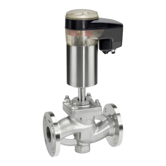
- Page 1 GEMÜ 539 eSyDrive Motorized globe valve Operating instructions further information webcode: GW-539...
- Page 2 All rights including copyrights or industrial property rights are expressly reserved. Keep the document for future reference. © GEMÜ Gebr. Müller Apparatebau GmbH & Co. KG 18.11.2019 GEMÜ 539 2 / 34 www.gemu-group.com...
-
Page 3: Table Of Contents
Contents 1 General information ..........Information ............Symbols used ............LED symbols ............Definition of terms ..........Warning notes ............. 2 Safety information ............ 3 Product description ........... 4 Order data ..............5 Technical data ............10 6 Dimensions ............... 16 7 Delivery .............. -
Page 4: General Information
1 General information 1 General information WARNING Potentially dangerous situation! 1.1 Information ▶ Non-observance can cause death or – The descriptions and instructions apply to the stand- severe injury. ard versions. For special versions not described in this document the basic information contained herein ap- plies in combination with any additional special docu- CAUTION mentation. -
Page 5: Safety Information
3 Product description 2 Safety information 3 Product description The safety information in this document refers only to an indi- 3.1 Buttons for on-site control vidual product. Potentially dangerous conditions can arise in combination with other plant components, which need to be considered on the basis of a risk analysis. - Page 6 3 Product description 3.2 LED displays Function LED MODE LED PWR Yellow Blue Green 3.2.1 On-site status LEDs Operation via LED MODE LED PWR emergency power supply module 3.2.2 High visibility LEDs Fig. 2: Position of the status LEDs The user checks the following conditions directly on-site at the valve using LED MODE and LED PWR: Function LED MODE...
- Page 7 3 Product description 3.5 Correct use Function High visibility LED Green Orange DANGER Location function Danger of explosion ▶ Risk of death or severe injury. Do not use the product in potentially ● explosive zones. 3.3 Description The GEMÜ 539 2/2-way globe valve has a hollow shaft actu- WARNING ator and is electrically operated.
-
Page 8: Order Data
4 Order data 4 Order data The order data provide an overview of standard configurations. Please check the availability before ordering. Other configurations available on request. Order codes 1 Type Code 8 Control module Code Globe valve, electrically operated, OPEN/CLOSE, positioner and process controller electro-mechanical hollow shaft actuator, 9 Regulating cone Code... - Page 9 4 Order data Order example Order option Code Description 1 Type Globe valve, electrically operated, electro-mechanical hollow shaft actuator, eSyDrive 2 DN DN 40 3 Body configuration 2/2-way body 4 Connection type Flange EN 1092, PN 25, form B, face-to-face dimension FTF EN 558 series 1, ISO 5752, basic series 1 5 Valve body material 1.4408, investment casting 6 Seat seal...
-
Page 10: Technical Data
5 Technical data 5 Technical data 5.1 Medium Working medium: Corrosive, inert, gaseous and liquid media which have no negative impact on the physical and chemical properties of the body and seal material. Max. permissible 600 mm²/s (cSt) viscosity: Other versions for lower/higher temperatures and higher viscosities on request. 5.2 Temperature Media temperature: -10 to 180 °C... - Page 11 5 Technical data Pressure/temperature Connection Material Max. allowable operating pressures in bar at temperature in °C correlation: types code code 16.0 16.0 14.5 13.4 25.0 25.0 22.7 21.0 40.0 40.0 36.3 33.7 19.0 16.0 14.8 13.6 16.0 16.0 15.5 14.7 17.2 16.0 14.8...
- Page 12 5 Technical data Control valve: Standard regulating cone (DIN) Kv values Operating Actuator linear Equal pressure version percentage RS851 RS861 RS852 RS862 10.0 RS853 RS863 10.0 RS854 RS864 16.0 RS855 RS865 25.0 RS856 RS866 25.0 RS784 RS794 40.0 RS857 RS867 40.0 RS785 RS795...
- Page 13 5 Technical data 5.4 Product compliance Food: Regulation (EC) No. 1935/2004* Regulation (EC) No. 10/2011* FDA* * depending on version and/or operating parameters Pressure Equipment 2014/68/EU Directive: Machinery Directive: 2006/42/EU 5.5 Mechanical data Protection class: IP 65 acc. to EN 60529 Actuator version 0A, 2A IP 61 acc.
- Page 14 5 Technical data 5.6 Electrical data Supply voltage: Actuator size 0 Actuator size 1 Actuator size 2 Voltage Uv = 24 V DC ± 10% Rating Max. 28 W Max. 65 W Max. 120 W Operating mode Continuous duty (OPEN/CLOSE operation) Operating mode Class C acc.
- Page 15 5 Technical data 5.6.2 Digital input signals Digital inputs: Function: selectable using software Voltage: 24 V DC Logic level "1": >14 V DC Logic level "0": < 8 V DC Input current: typ. 2.5 mA (at 24 V DC) 5.6.3 Analogue output signals 5.6.3.1 Actual value Output signal: 0/4 - 20 mA;...
-
Page 16: Dimensions
6 Dimensions 5.6.5 Communication Interface: Ethernet Function: Parameterisation via web browser IP address: 192.168.2.1 alterable via web browser Subnet screen: 255.255.252.0 alterable via web browser The actuator and the PC must be in the same network to use the web server. The IP address of the actuator is entered in the web browser and the actuator can then be parametrised. - Page 17 6 Dimensions Actuator version Actuator version Actuator version Dimensions in mm 6.2 Actuator dimensions ØB Actuator version 45.0 68.0 126.0 160.0 193.0 86.0 82.0 132.0 172.0 252.0 121.0 129.0 157.0 224.0 304.0 Dimensions in mm 17 / 34 www.gemu-group.com GEMÜ 539...
- Page 18 6 Dimensions 6.3 Body dimensions 6.3.1 Flange connection types code 8 DN 15 - 50 DN 65 - 100 Connection types code 8 Material code ø D ø L ø K ø D ø L ø K 130.0 95.0 14.0 65.0 150.0 105.0...
- Page 19 6 Dimensions 6.3.2 Flange connection types code 10, 11, 48 DN 15 - 50 (code 10, 48) DN 40, 50 (code 11) Connection types code Material code 37 ø D ø L ø k ø D ø L ø K ø...
- Page 20 6 Dimensions 6.3.3 Flange connection types code 39 DN 15 - 50 DN 65 - 100 Connection types code 39 Material code 37,90 ø D ø L ø K 130.0 90.0 15.9 60.3 150.0 100.0 15.9 69.9 160.0 110.0 15.9 79.4 180.0 115.0...
-
Page 21: Delivery
10 Installation in piping 7 Delivery 10 Installation in piping ● Check that all parts are present and check for any damage 10.1 Preparing for installation immediately upon receipt. WARNING The product's performance is tested at the factory. The scope of delivery is apparent from the dispatch documents and the The equipment is subject to pressure! design from the order number. -
Page 22: Installation Position
10 Installation in piping NOTICE NOTICE Tools Connector elements ▶ The tools required for installation and assembly are not ▶ The connector elements are not included in the scope of included in the scope of delivery. delivery. Use appropriate, functional and safe tools. Only use connector elements made of approved materi- ●... -
Page 23: Electrical Connection
11 Electrical connection 11 Electrical connection Signal name Pin 3 Tx - (Ethernet) NOTICE Pin 4 Rx - (Ethernet) Appropriate cable socket/appropriate mating connector! Pin 5 Shield ▶ The appropriate cable socket and/or appropriate mating connector is included for X1, X3 and X4. 11.3 Connection X3 ▶... -
Page 24: Network Connection
12 Network connection 13.2 Commissioning via the eSy-Web web interface CAUTION ● See separate eSy-Web operating instructions. Hot actuator parts! ▶ Risk of burns! 13.3 Commissioning via digital input Only work on plant that has cooled ● down. ü The function of input 3 is set to init. If necessary, wear gloves when work- 1. -
Page 25: Manual Override
15 Inspection and maintenance 14.3 Manual override Groove for actuator WARNING Rotating cover! ▶ Risk of crushing. Disconnect the power supply before ● using the manual override. 1. Disconnect the power supply. 2. Turn housing cover 3 clockwise. 3. Remove housing cover 3. Starting point for manual override 5. -
Page 26: Spare Parts
15 Inspection and maintenance Item Name Order description NOTICE Spindle Exceptional maintenance work! Valve plug ▶ Damage to the GEMÜ product. Any maintenance work and repairs not described in these Retaining washer ● operating instructions must not be performed without Stud bolt consulting the manufacturer first. -
Page 27: Replacing The Seals Dn 65 - Dn 100
15 Inspection and maintenance 15.3.2 Replacing the seals DN 65 - DN 100 15.4 Mounting the actuator 1. Remove the actuator. CAUTION 2. Bend the locking plate h 90°, so that it lies flat on the valve Incorrect combination of actuator and plug c. -
Page 28: Mounting Actuator Dn 15 - Dn 50
15 Inspection and maintenance 15.4.1 Mounting actuator DN 15 - DN 50 1. Move the actuator A to the open position. 2. Lubricate the thread of the union nut a using a suitable lubricant. 3. Place actuator A on valve body 1 approx. 90° in front of the end position (orientation of the connections) and screw hand tight with union nut a. -
Page 29: Troubleshooting
16 Troubleshooting 16 Troubleshooting Error Possible cause Troubleshooting The product leaks downstream (doesn't Operating pressure too high Operate the product with operating close or doesn't close fully) pressure specified in datasheet Valve body leaks or is damaged Check valve body for potential damage, replace valve body if necessary The product doesn't close or doesn't The actuator design is not suitable for the... -
Page 30: Removal From Piping
17 Removal from piping 17 Removal from piping 19 Returns 1. Remove in reverse order to installation. Legal regulations for the protection of the environment and personnel require that the completed and signed return deliv- 2. Unscrew the electrical wiring. ery note is included with the dispatch documents. -
Page 31: Declaration Of Incorporation According To 2006/42/Ec (Machinery Directive)
20 Declaration of Incorporation according to 2006/42/EC (Machinery Directive) 20 Declaration of Incorporation according to 2006/42/EC (Machinery Directive) Declaration of Incorporation according to the EC Machinery Directive 2006/42/EC, Annex II, 1.B for partly completed machinery GEMÜ Gebr. Müller Apparatebau GmbH & Co. KG Fritz-Müller-Straße 6-8 74653 Ingelfingen-Criesbach, Germany declare that the following product... -
Page 32: Declaration Of Conformity According To 2014/68/Eu (Pressure Equipment Directive)
21 Declaration of conformity according to 2014/68/EU (Pressure Equipment Directive) 21 Declaration of conformity according to 2014/68/EU (Pressure Equipment Directive) EU Declaration of Conformity in accordance with 2014/68/EU (Pressure Equipment Directive) GEMÜ Gebr. Müller Apparatebau GmbH & Co. KG Fritz-Müller-Straße 6-8 74653 Ingelfingen-Criesbach, Germany declare that the product listed below complies with the safety requirements of the Pressure Equipment Directive 2014/68/EU. -
Page 33: Declaration Of Conformity According To 2014/30/Eu (Emc Directive)
22 Declaration of conformity according to 2014/30/EU (EMC Directive) 22 Declaration of conformity according to 2014/30/EU (EMC Directive) EU Declaration of Conformity according to 2014/30/EU (EMC Directive) GEMÜ Gebr. Müller Apparatebau GmbH & Co. KG Fritz-Müller-Straße 6-8 74653 Ingelfingen-Criesbach, Germany declare that the product listed below complies with the safety requirements of the EMC Directive 2014/30/EU. - Page 34 GEMÜ Gebr. Müller Apparatebau GmbH & Co. KG Subject to alteration Fritz-Müller-Straße 6-8, 74653 Ingelfingen-Criesbach, Germany 11.2019 | 88614468 Phone +49 (0)7940 123-0 · info@gemue.de *88614468* www.gemu-group.com...