
Related Manuals for Honeywell NOTIFIER UDACT-2


Summary of Contents for Honeywell NOTIFIER UDACT-2
- Page 1 Universal Digital Alarm Communicator/ Transmitter UDACT-2 Document 54089 Rev: B3 10/29/2019 ECN: 18-305...
- Page 2 Fire Alarm & Emergency Communication System Limitations While a life safety system may lower insurance rates, it is not a substitute for life and property insurance! An automatic fire alarm system—typically made up of smoke Heat detectors do not sense particles of combustion and alarm detectors, heat detectors, manual pull stations, audible warning only when heat on their sensors increases at a predetermined rate devices, and a fire alarm control panel (FACP) with remote notifica-...
- Page 3 HARSH™, NIS™, and NOTI•FIRE•NET™ are all trademarks; and Acclimate® Plus™, eVance®, FlashScan®, FAAST Fire Alarm Aspiration Sensing Technology®, Honeywell®, Intelligent FAAST®, NOTIFIER®, ONYX®, ONYXWorks®, SWIFT®, VeriFire®, and VIEW® are all registered trademarks of Honeywell International Inc. Microsoft® and Windows® are registered trademarks of the Microsoft Corporation. Chrome™ and Google™ are trademarks of Google Inc. Firefox® is a registered trademark of The Mozilla Foundation.
- Page 4 • Your suggestion for how to correct/improve documentation Send email messages to: FireSystems.TechPubs@honeywell.com Please note this email address is for documentation feedback only. If you have any technical issues, please contact Technical Services. UDACT-2 — Instruction Manual P/N 54089:B3 10/29/2019...
-
Page 5: Table Of Contents
Table of Contents Section 1: Overview ................................7 1.1: Introduction ........................................7 1.2: UL 864 Compliance......................................7 1.2.1: Products Subject to AHJ Approval.................................7 1.2.2: Programming Features Subject to AHJ Approval ..........................7 1.3: Related Documentation .....................................7 1.4: Description.........................................8 1.5: Features..........................................8 1.6: Specifications........................................8 1.6.1: DC Power - TB1 .....................................8 1.6.2: EIA-485 - TB2......................................9 1.6.3: Earth - TB2 ......................................9 1.6.4: Relay Drive - TB4 ....................................9... - Page 6 Table of Contents A.3.2: Mounting......................................37 A.3.3: Wiring ........................................37 A.4: NCA-2 (UL 864 10th), NCA (UL 8th)................................40 A.4.1: General.........................................40 A.4.2: Mounting......................................40 A.4.3: Wiring ........................................40 A.5: AM2020/AFP1010 (UL 8th)...................................43 A.5.1: General.........................................43 A.5.2: Mounting......................................43 A.5.3: Wiring ........................................43 A.6: NFS2-3030 (UL 864 10th), NFS-3030 (UL 8th) ............................45 A.6.1: General.........................................45 A.6.2: Mounting......................................45 A.6.3: Wiring ........................................45...
-
Page 7: Section 1: Overview
Section 1: Overview 1.1 Introduction This document contains information for installing, programming and operating the UDACT-2, Universal Digital Alarm Communica- tor/Transmitter. 1.2 UL 864 Compliance 1.2.1 Products Subject to AHJ Approval This product has been certified to comply with the requirements in the Standard for Control Units and Accessories for Fire Alarm Sys- tems, UL 864 10th Edition. -
Page 8: Description
Overview Description 1.4 Description The Universal Digital Alarm Communicator/Transmitter (UDACT-2) may be used with a variety of control panels. The UDACT-2 trans- mits system status to UL Listed Central Station Receivers, using modular jacks to interface primary and secondary phone lines to the public switched telephone network. -
Page 9: 2: Eia-485 - Tb2
REN for the calling area. Before connecting the UDACT-2 to the public switched telephone network, the installation of two RJ31X jacks is necessary. The follow- ing information is provided if required by the local telephone company: Honeywell Life Safety 12 Clintonville Road Manufacturer:... -
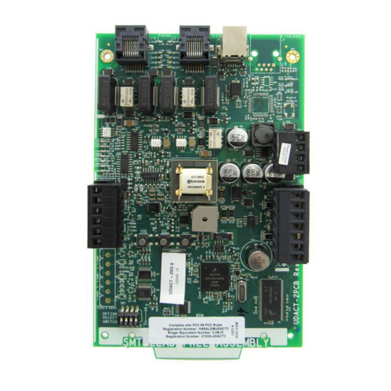
Page 10: Board Layout
Overview Board Layout “NOTICE: The Canadian Department of Communications label identifies certified equipment. This certification means that the equip- ment meets certain telecommunications network protective, operational and safety requirements. The Department does not guarantee the equipment will operate to the user's satisfaction. Before installing this equipment, users should ensure that it is permissible to be connected to the facilities of the local telecommunica- tions company. - Page 11 Board Layout Overview LED # LED Name Color Function EIA-485 COMM LOSS Yellow Illuminates when the EIA-485 port loses communication. REAL TIME Yellow Illuminates when the real time clock is not functioning properly. It also may light during power-up after the UDACT-2 has been turned off for awhile.
- Page 12 Overview Board Layout Switch # Switch Name Description TEST REPORT Press and hold this button switch down for over 3 seconds to have the UDACT-2 transmit a test message to both Central Stations. The message reported is the same as the automatic test message for all formats except Ademco Contact ID.
-
Page 13: Section 2: Installation And Wiring
Section 2: Installation and Wiring 2.1 Installation Options The UDACT-2 is either installed internally in the panel cabinet or remotely in an ABS-8RB, UBS-1B or UBS-1R enclosure. The follow- ing table contains information specific to each panel that is compatible with the UDACT-2. See "Internal Installation" on page 13 for instructions on internal installation and "Remote Installation"... - Page 14 Installation and Wiring Installation Options NFS2-640 Chassis Mounting The UDACT-2 is installed on the NFS2-640 chassis within the NFS2-640 backbox as described and shown below: Step Action Disconnect AC power and disconnect batteries. Position the UDACT-2 on the standoffs and fasten with #4-40 screws. NOTE: The UDACT-2 can be mounted in the fourth column of the NFS2-640 Chassis.
- Page 15 Installation Options Installation and Wiring NOTE: The UDACT-2 can be mounted only in one of the front positions of this chassis. Four Possible Mounting Positions Screws Chassis slot Figure 2.4 CHS-4 Installation CHS-4L The UDACT-2 may be mounted in the CHS-4L chassis within the control panel backbox as described and shown below. Step Action Disconnect AC power and disconnect batteries.
- Page 16 Installation and Wiring Installation Options Screws Figure 2.6 CA-1 Installation CA-2 The UDACT-2 may be mounted in the CA-2 chassis behind the DVC, NFS2-3030 or NCA-2 as described and shown below. Step Action Disconnect AC power and disconnect batteries. Position the UDACT-2 on the standoffs and fasten with #4 screws.
- Page 17 Installation Options Installation and Wiring Rear Mounting Screws Screws Screws Front Mounting (two possible positions) Figure 2.8 CHS-M3 Installation BMP-1 Blank Module Plate The UDACT-2 mounts on the back of a BMP-1 blank module plate, so it can be mounted on a DP-DISP, DP-DISP2, or ADP-4B dress panel.
- Page 18 Installation and Wiring Installation Options ABS-8RB The UDACT-2 comes with an insulating barrier that must be used in this installation. Step Action Place the UDACT-2 inside the folds of the insulating barrier, as shown below. Align the UDACT-2 and insulating barrier over the four (4) threaded standoffs at the back of the ABS-8RB enclosure. Secure using the four (4) screws supplied with the enclosure.
-
Page 19: Tb1 - 24 Vdc Power Connections
TB1 - 24 VDC Power Connections Installation and Wiring 2.2 TB1 - 24 VDC Power Connections 24 VDC filtered, non-resettable power is connected between the Main Power Supply of the panel and the UDACT-2 using twisted pair wire. One +24V and one Common terminal are used for input from the power +24 VDC Power source. -
Page 20: Relay Driver (Auxiliary Output) Connections - Tb4
Installation and Wiring Relay Driver (Auxiliary Output) Connections - TB4 Important! The UDACT-2 must not be used to dial a phone number that is call-forwarded per requirements of UL 864 10th Edition. Secondary Lines - Incoming Telco Phone Lines To Premise Phones To Premise Phones Green Ring... - Page 21 Relay Driver (Auxiliary Output) Connections - TB4 Installation and Wiring When the UDACT-2 is programmed for “Receive/Transmit”, EIA-485 supervision and UDACT-2 trouble status are automatically han- dled by the host control panel. The relay output may, however, be used for UDACT-2 communications failure if desired. Relay Energized LED DPDT Contacts 10 Amps @115 VAC...
-
Page 22: Usb Port - J6
Installation and Wiring USB Port - J6 2.7 USB Port - J6 The UDACT-2’s USB port (J6) provides a USB Type B connection J6 - USB for a computer running VeriFire Tools for UDACT-2 program- Type B ming. connection UDACT-2 Figure 2.18 USB Port, J6 2.8 UL Power-limited Wiring Requirements Power-limited and nonpower-limited circuit wiring must remain separated in the cabinet. -
Page 23: Section 3: Programming
Section 3: Programming The UDACT-2 is programmed using VeriFire Tools, version 6.6 or higher. NOTE: Only one UDACT-2 can be installed on a host’s EIA-485 ACS circuit. NOTE: Check the time on the laptop used for VeriFire Tools programming for accuracy. The 24 hour test time is determined from the laptop’s time signature taken from the downloaded VeriFire Tools database. -
Page 24: General Settings 2
Programming General Settings 2 - 32 addresses - 1-32 - for point reporting CAUTION: THE START ADDRESS MUST EQUAL THE HOST’S UDACT-2 ACS ADDRESS. - The NFS2-640, NFS-640, NFS-320/NFS-320SYS use: - two monitoring addresses - 20 and 21 - for zone reporting. - ten monitoring addresses - 22 through 31 - for point reporting. -
Page 25: Primary Number Event Codes
Primary Number Event Codes Programming Primary 24 Hour Test Time: Enter the start time (in HH:MM format, where HH = 00 to 23 hours, MM = 00 to 59 minutes) at which the test should be performed and transmitted. The first test will be performed at that time, and again as indicated by the Test Time Interval setting. -
Page 26: Secondary Number Event Codes
Programming Secondary Number Event Codes Default: Press to return the Setting fields to default values. 3.4 Secondary Number Event Codes This screen displays the default Event Code assignments for the protocol selected for the secondary telephone line. The Event Codes are user-programmable Figure 3.4 Secondary Number Event Codes Tab Description: This display-only field gives a text description of the Event Code. -
Page 27: Report
Report Programming Function: Defaults to Fire Alarm. From the pull-down menu, select the point/zone type that matches the FACP’s point type. Point/zone type selections are: • Fire Alarm • Water Flow • 24 Hour Non-Burglary • Pump Failure • Disabled •... -
Page 28: Section 4: Operation
Section 4: Operation 4.1 Switches 4.1.1 SW1 - Option Select Switch This DIP switch gives the user four UDACT-2 settings. • Switch DIP1 - Download App mode. Set to ON prior to downloading an application file. Set to OFF when download is complete. -
Page 29: Section 5: Reporting Formats
Section 5: Reporting Formats The formats sent by the UDACT-2 to the Central Station are set out in this section. Event codes are defined for each protocol. Use Ademco Contact ID for specific zone or point identification. Pulsed formats typically require 15 to 20 seconds for message transmission. Refer to Section 6.1, “Compatible UL Listed Receivers”, on page 33 for a list of compatible receivers. - Page 30 Reporting Formats Ademco Contact ID • 3 = New Restore • XYZ = Event code. Refer to Table 5.2 for event code definitions. • GG = Group number. Zeroes, or the value defined in VeriFire Tools programming. (Refer to page 24.) •...
-
Page 31: Sia
Reporting Formats A typical printout of alarm and trouble reports in the Ademco Contact ID Reporting Structure follows: Rcvr/ Time Date SSSS QXYX CCCC Description Line ID 11:28 10/14 2456 E110 C000 General Alarm 11:28 10/14 2456 E111 C046 Alarm SD46 11:28 10/14 2456... - Page 32 Reporting Formats Event Event Code Description Code Description Code Code General fault restore Zone/point defined as heat detector restore AC fault restore Zone/point defined as water flow restore Zone/point fault restore Zone/point defined as duct detector restore Low battery fault restore Zone/point defined as pre-alarm restore Telco primary line fault restore Zone/point defined as smoke restore...
-
Page 33: Section 6: Compatible Ul Listed Receivers
Section 6: Compatible UL Listed Receivers 6.1 UL Listed Receivers The chart below shows UL listed receivers compatible with the UDACT-2. A check in the protocol column indicates the receiver sup- ports that protocol. Ademco Receiver Standard Contact 1800/2300 Ademco 685 (1) ... -
Page 34: Appendix A: Panel-Specific Information
Appendix A: Panel-Specific Information A.1 AFP-200 A.1.1 General The UDACT-2 is capable of reporting a maximum of 99 zones when used with the AFP-200.For the UDACT-2 to correctly report a zone to the Central Station, both the panel and the UDACT-2 must have each zone programmed as the same function type (refer to "Zone and Point Assignments"... -
Page 35: A.2: Afp-300/Afp-400
AFP-300/AFP-400 Panel-Specific Information Below is a remote installation of a UDACT-2 with an AFP-200: To Phone Lines (supervised) Remote Cabinet Wires in conduit AFP-200 Circuit Board Solid Earth Ground Connection Figure A.1 UDACT-2 and AFP-200 A.2 AFP-300/AFP-400 A.2.1 General The UDACT-2 is capable of reporting a maximum of 99 zones or 256 points when used with the AFP-300, and 99 zones or 448 points when used with the AFP-400. - Page 36 Panel-Specific Information AFP-300/AFP-400 Notes Recommended wire is 12 AWG (3.25mm ) to 18 AWG (0.75mm ), twisted pair, shielded cable. Connect only one end of shield: a) shield may be connected to cabinet (earth ground) at fire alarm panel, or b) shield may be connected to a Common Terminal at TB2 on the UDACT-2 as shown in Figure A.3.
-
Page 37: A.3: Nfs2-640 (Ul 864 10Th), Nfs-320/Sys (Ul 864 10Th), Nfs-640 (Ul 8Th)
NFS2-640 (UL 864 10th), NFS-320/SYS (UL 864 10th), NFS-640 (UL 8th) Panel-Specific Information Below is an internal installation of a UDACT-2 with an AFP-300/AFP-400: To Phone Lines (supervised) CPU-300/400 MPS-400 Connect to CHS-4 Chassis Figure A.3 AFP-300/AFP-400 and UDACT-2 in CAB-3/4 A.3 NFS2-640 (UL 864 10th), NFS-320/SYS (UL 864 10th), NFS-640 (UL 8th) A.3.1 General The UDACT-2 is capable of reporting a maximum of 99 zones, or 636 ACS points when used with the NFS2-640 or NFS-640. - Page 38 Panel-Specific Information NFS2-640 (UL 864 10th), NFS-320/SYS (UL 864 10th), NFS-640 (UL 8th) Connect the Ground Wire (PN 71073, provided) from the UDACT-2 terminal on TB2 to the CHS-4 Chassis or to a solid building EARTH earth ground. Connect 24VDC filtered, non-resettable power from the CPU2-640 TB10 to TB1 24V+ and 24V- terminals on the UDACT-2. To the NFS-640 Connect the communication line between the EIA-485 terminal block TB13 on the CPU2-640 and TB2 terminals EIA-485+ and EIA- 485- on the UDACT-2, being certain to observe polarity.
- Page 39 NFS2-640 (UL 864 10th), NFS-320/SYS (UL 864 10th), NFS-640 (UL 8th) Panel-Specific Information Below is an internal installation of a UDACT-2 with an NFS2-640/NFS-320/NFS-320SYS: To Phone Lines (supervised) NFS2-640/NFS-320/NFS- 320SYS Solid Earth Ground Connection Figure A.5 UDACT-2 and NFS2-640/NFS-320/NFS-320SYS in the Same Cabinet Below is a remote installation of a UDACT-2 with an NFS-640: To Phone Lines (supervised)
- Page 40 Panel-Specific Information NCA-2 (UL 864 10th), NCA (UL 8th) Below is an internal installation of a UDACT-2 with an NFS-640: To Phone Lines (supervised) NFS-640 in Same Cabinet Connect to Chassis Figure A.7 UDACT-2 and NFS-640 in the Same Cabinet A.4 NCA-2 (UL 864 10th), NCA (UL 8th) A.4.1 General The UDACT-2 is capable of reporting a maximum of 2040 ACS points when used with the NCA or NCA-2.
- Page 41 NCA-2 (UL 864 10th), NCA (UL 8th) Panel-Specific Information Notes Recommended wire is 12 AWG (3.25mm ) to 18 AWG (0.75mm ), twisted pair, shielded cable. Connect only one end of shield: a) shield may be connected to cabinet (earth ground) at fire alarm panel, or b) shield may be connected to TB1 Terminal 5 (Shield) at UDACT-2 as shown in Figure A.8.
- Page 42 Panel-Specific Information NCA-2 (UL 864 10th), NCA (UL 8th) Below is an internal installation of a UDACT-2 with an NCA: To Phone Lines (supervised) Connect to Chassis Figure A.9 UDACT-2 and NCA in the Same Cabinet Below is a remote installationof a UDACT-2 with an NCA-2 using power supplied by the control panel: To Supervised Phone Lines Remote Cabinet...
- Page 43 AM2020/AFP1010 (UL 8th) Panel-Specific Information Below is a remote installation of a UDACT-2 with an NCA-2 using power supplied by an AMPS-24/E: To supervised phone lines Remote Cabinet Wires in conduit CAB-3/4 Series Cabinet EIA-485 (ACS Mode) TB7 on NCA-2 +24 VDC non-resettable power TB3 AUX 24 output...
- Page 44 Panel-Specific Information AM2020/AFP1010 (UL 8th) Connect 24 VDC filtered, regulated power from the MPS-24A or MPS-24B (Main Power Supply) to +24V and -24V terminals on the UDACT-2. Notes Recommended wire is 12 AWG (3.25mm ) to 18 AWG (0.75mm ), twisted pair, shielded cable. Connect only one end of shield: a) shield may be connected to cabinet (earth ground) at fire alarm panel, or b) shield may be connected to TB1 Common at the UDACT-2 as shown in Figure A.12.
- Page 45 NFS2-3030 (UL 864 10th), NFS-3030 (UL 8th) Panel-Specific Information Below is an internal installation of UDACT-2 with an AM2020/AFP1010 using an MPS-24B main power supply: To Phone Lines (supervised) EIA-485 Interface SIB-2048 MPS-24B Connect to CHS-4 Chassis Figure A.13 UDACT-2 and AM2020/AFP1010 with MPS-24B A.6 NFS2-3030 (UL 864 10th), NFS-3030 (UL 8th) A.6.1 General The UDACT-2 is capable of reporting up to 2,040 ACS points when used with the NFS2-3030/NFS-3030.
- Page 46 Panel-Specific Information NFS2-3030 (UL 864 10th), NFS-3030 (UL 8th) Notes Recommended wire is 12 AWG (3.25mm ) to 18 AWG (0.75mm ), twisted pair, shielded cable. Connect only one end of shield: a) shield may be connected to cabinet (earth ground) at fire alarm panel, or b) shield may be connected to Common on TB2 on the UDACT-2.
- Page 47 NFS2-3030 (UL 864 10th), NFS-3030 (UL 8th) Panel-Specific Information Below is a remote installation of a UDACT-2 with an NFS2-3030 using power supplied by the control panel: To supervised phone lines Remote Cabinet Wires in CAB-3/4 Series Cabinet conduit EIA-485 (ACS Mode) TB7 on control panel...
- Page 48 Index Numerics Communicator Failure 20 Line Seizure 8 Compatibility Document 7 24 hour test time accuracy 23 Compatible 24 VDC 19 panels and network annunciators 8 4 + 2 Main Power Supply 19 Receivers 33 programming 24 MPS-24A 44 Connections Some receivers display A as zero.
- Page 49 Index Remote installation nonpower-limited 22 NFS2-3030 47 power limited 22 NFS-3030 46 Relay Driver 20 remote installation AFP-200 35 AFP-300/400 36 zone 29 NCA 41 NCA-2 42 NCA-2/AMPS-24 43 NFS2-640 38 NFS-3030/NFS2-3030/AMPS-24 47 NFS-320 38 NFS-320/NFS-320SYS 38 NFS-640 39 resistance 19 Ringer Equivalence Number (REN) 9 RJ31X 9 shielded cable 34...
- Page 50 Index UDACT-2 — Instruction Manual P/N 54089:B3 10/29/2019...
- Page 51 Manufacturer Warranties and Limitation of Liability Manufacturer Warranties. Subject to the limitations set forth herein, Manufacturer warrants that the Products manufactured by it in its Northford, Connecticut facility and sold by it to its authorized Distributors shall be free, under normal use and service, from defects in material and workmanship for a period of thirty six months (36) months from the date of manufacture (effective Jan.
- Page 52 NOTIFIER 12 Clintonville Road Northford, CT 06472-1610 USA 203-484-7161 www.notifier.com...