Table of Contents
Advertisement
PN782164 REV 20170627
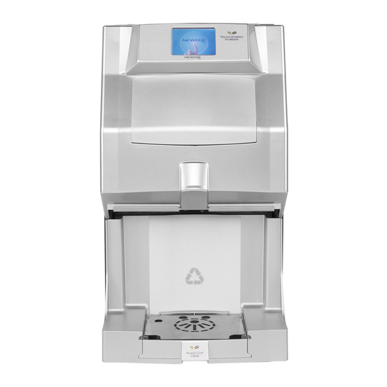
SINGLE SERVING AUTOMATIC POD MACHINE
FKP-4T
NEWCO ENTERPRISES INC,
3650 NEW TOWN BLVD
SAINT CHARLES, MO 63301
1-800-325-7867
FAX 1-636-925-0029
Features/ Specifications
AUTOMATIC POD REMOVAL
•
TOUCHSCREEN OPERATION
•
FLOWMETER
•
• UP TO 20 OZ TRAVEL MUG
LARGE POD WASTE TRAY / THRU COUNTER OPTION
•
ADJUSTABLE DRINK STRENGTH
•
ADJUSTABLE DRINK VOLUME
•
•
USB INTERFACE
1
Advertisement
Table of Contents

Related Manuals for Newco FKP-4T


Summary of Contents for Newco FKP-4T
- Page 1 PN782164 REV 20170627 SINGLE SERVING AUTOMATIC POD MACHINE FKP-4T NEWCO ENTERPRISES INC, 3650 NEW TOWN BLVD SAINT CHARLES, MO 63301 1-800-325-7867 FAX 1-636-925-0029 Features/ Specifications AUTOMATIC POD REMOVAL • TOUCHSCREEN OPERATION • FLOWMETER • • UP TO 20 OZ TRAVEL MUG LARGE POD WASTE TRAY / THRU COUNTER OPTION •...
- Page 2 LEFT BLANK INTENTIONALLY...
-
Page 3: Table Of Contents
TABLE OF CONTENTS SPECIFICATIONS................... 4 NEWCO PRODUCT WARRANTY ..............5 MACHINE SET-UP..................6 MACHINE OPERATION.................. 8 MACHINE PROGRAMMING................. 10 USB INTERFACE……………………............. 18 DRAINING THE HOT WATER TANK ............22 SERVICING THE MACHINE ................ 23 REMOVING THE BREW MECHANISM............23 SIDE PANEL REMOVAL ................24 TANK REMOVAL &... -
Page 4: Specifications
SPECIFICATIONS TANK WATTAGES US 1700W 120V- CANADA 1400W 120V- INTERNATIONAL 1700W 220V TANK CAPACITY-1 US GALLON DRIP TRAY CAPACITY 8 OUNCES POD WASTE TRAY CAPACITY 40 PODS UP TO 20 OZ CUP SIZE... - Page 5 SHIPPING WT-APPROX 35 LBS...
-
Page 6: Newco Product Warranty
AT NEWCO’S SOLE OPTION AS SPECIFIED HEREIN, TO REPAIR, REPLACEMENT OR REFUND. In no event shall Newco be liable for any other damage or loss, including, but not limited to, lost profits, lost sales, loss of use of equipment, claims of Buyer’s customers, cost of capital, cost of down time, cost of... -
Page 7: Machine Set-Up
MACHINE SET-UP NOTE: The FRESH CUP machine weighs approximately 35 LBS. Use CAUTION when LIFT MACHINE FROM MACHINE BOTTOM ONLY. unpacking and lifting machine. DO NOT MOVE MACHINE UNLESS THE HOT WATER TANK IS DRAINED AND EMPTY. Open and install the drip tray grill and place drip tray into waste bin. 2. - Page 8 Turn the power switch to the “OFF” position and plug the machine into a properly installed and grounded electrical circuit. Turn on power switch to start the initial WATER FILL CYCLE. This screen will display momentarily with hardware and software revision levels. This will be displayed until water level reaches the liquid level probe.
-
Page 9: Machine Operation
MACHINE OPERATION To dispense a drink, place a cup under the brew nozzle, press a brew selection and place a pod flat side up (not necessary if the drink selection does not use a pod) Once a selection is made a Submenu for Drink Settings will appear. BREWER MESSAGE DISPLAY Coffee Drinks Espresso Drinks... - Page 10 DRINKS SUB-MENUS Cup Size Selections Highlighted Mug is SELECTED SIZE Small –Medium- Large Use to Change Cup Size Default 7-8-9 Cup Strength Selections Mild –Medium- Bold Use to Change Return Button Coffee Strength Returns to Previous Screen Brew Button Starts Brewing Cycle Cancel Button Stops Brewing...
-
Page 11: Machine Programming
MACHINE PROGRAMMING Fig 1: Program Settings To enter a programming setting, press and hold the upper right hand corner of the touch screen when powering up machine The Fresh Cup pod brewer has a programming menu that consists of eight icons. The current entries in the Main menu are as follows: Temperature Recipes... - Page 12 Set Temperature : In this entry the user may set the tank temperature in the range of 180 to 203 degrees Fahrenheit with the default at 200 degrees F. Pressing the green (+) and (-) buttons will change the set point, incrementing or decrementing by one. Pressing the Blue “Return”...
- Page 13 Set Pod Count : In this entry the user may set the number of pods the brewer will hold before signaling that the bin is full. The range is 10 to 100 pods, with the default at 30. Setting the pod count under 10 turns off the counter so the empty waste bin message will not display.
- Page 14 Recipe Settings : This entry takes the user into a sub menu to program the parameters unique to each recipe. There are six entries in the RECIPE Parameters sub menu: SET BREW VOLUME : This entry sets the volume in ounces for this key to dispense. The Range is from 2.0 to 16 ounces with the default set to 7 ounces for small, 8ounces for medium, and 9 ounces for large.
- Page 15 RECIPE GUIDE Step 2 – If desired, change Step 1 – Make Step 3 – If desired, change drink volume using the green drink selection recipe parameters using the buttons. Then, press NEXT green buttons. Then, press BACK NEXT BACK Note: For recipes other than Espresso, drink size and strength must be selected before access to recipe parameters will be allowed.
- Page 16 Select Water Filter : This entry allows the user to select the filter size for the filter used on the inlet for the water. Choices include OFF, 500 GAL UP TO 3000 GAL. These set the counter for the filter warning. Whenever water is dispensed the counter is incremented to account for the water dispensed.
- Page 17 Fig 2: Factory Programming Settings This menu is accessed by holding the lower right corner of the touchscreen when cycling power to the machine. Continue to hold until the Factory Programming Menu Appears Drain Water Lines Flowmeter Test Remove Excess Flow Meter Water in lines prior Diagnostic Test...
- Page 18 Machine Options : This Menu determines which items are displayed on the Main Program Menus. Green buttons indicates that the selection is active, grey buttons are inactive Cup Size Selection Drink Strength Selection Toggles which cup sizes appear on the Toggles which Drink Selection Strength Selections...
-
Page 19: Usb Interface
Drink Recipes. 3. Future Firmware Updates. Any future Firmware or Graphics updates will be e-mailed from Newco with instructions on how to load. The connection is located behind the waste bin, next to the waste bin detection switch, and is accessed by removing the waste bin assembly and protective plug from the USB socket. - Page 20 USER GRAPHICS USING THE USB HEADER INTERFACE User generated graphics files • Three Specific Bitmap files (BMP) can be loaded directly from a USB Flash Drive into the Fresh Cup 4 Display. These files must be 8 bit 320 x 240 pixel format and Landscape oriented, and output as a Window Bitmap file.
- Page 21 To load the file into the Fresh Cup 4 Touch, turn off the power switch, insert the Flash drive into the USB outlet, and switch the power back on. The screen will remain blank and the Blue Cup light will begin to flash. A message will then be displayed that indicates the new file has been transferred as displayed by the green status bar.
- Page 22 NOTE: IF A PHONE NUMBER HAS BEEN ENTERED UNDER THE CALL FOR SERVICE MENU OPTION IT WILL BE DISPLAYED ON THE ESERVICE SCREEN. Custom Splash Screen Graphic—this graphic image is displayed when the power to the machine is cycled on. This is the only place this graphic is seen.
-
Page 23: Draining The Hot Water Tank
saved as filename, recipes. When viewed in a file browser the filename should appear as recipes.txt and saved or transferred to the USB flash storage device. Recipe selection Screen from the Application Recipes.exe Note—use the Utils Menu to reset the recipe values to the Factory Defaults. DRAINING THE HOT WATER TANK THE DRAIN TUBE IS CLIPPED TO THE TANK PLATE IN FRONT OF THE TANK. -
Page 24: Servicing The Machine
SERVICING THE MACHINE The Fresh Cup machine has a modular Water Tank Assembly and Brew Mechanism. These assemblies can be easily removed from the machine by removing or loosening Machine nuts as noted in drawings below: REMOVING THE BREW MECHANISM BREW MECHANISM ACCESS... -
Page 25: Side Panel Removal
SIDE PANEL REMOVAL 3. SLIDE PANEL 1. LOOSEN (2) TO THE SCREWS THEN REAR OF REMOVE COVER PANEL MACHINE 2. REMOVE (2) SCREWS FROM REAR OF SIDE PANEL 5. SLIDE PANEL DOWN 4. LIFT PANEL UP AND RELEASE TOP FLANGE 6. -
Page 26: Tank Removal & Access Areas
TANK REMOVAL & ACCESS AREAS REMOVE (3) 8-32 NUTS TO PREPARE TANK FOR REMOVAL (TWO ON TOP OF TANK & ONE ON BOTTOM OF PUMP BRACKET LOOSEN SCREWS BOTH SIDES TO REMOVE TOP & BACK COVERS REMOVE (2) 6-32 SCREWS LOOSEN BUT DO NOT TO REMOVE SIDE PANEL REMOVE THESE 2... -
Page 27: Pod Brewing Mechanism
POD BREWING MECHANISM 780585-UNIV 2 ITEM # PART NUMBER DESCRIPTION QTY/EA 780230 BREW MECH MOTOR 780231 DELTROL SOLENOID 780587 LOWER BREW CHAMBER UNIVERSAL 2 773246 U-CUP SEAL RING 780539 UPPER BREW CHAMBER 780554 EJECT SLOPE CAM ASS’Y 780588 MOLDED BUMP DISC PAD 780546 KICKER SLIDE WASHER 780536... -
Page 28: Tank Ass'y
TANK ASS’Y 780609 ITEM # PART NUMBER DESCRIPTION QTY/EA 110958 RELAY, 12 VDC SPST 30A 111593 HI-LIMIT THERMOSTAT 109937 GEAR PUMP ASS’Y 781772 PUMP ASS’Y W/ELBOW (HOT WATER) 780253 TANK ONLY 773056 AIR PUMP, POD 500396 LIQUID LEVEL PROBE& BUSHING 151677 DUAL TEMP THERM PROBE 100149... -
Page 29: Electrical Components
ELECTRICAL COMPONENTS ITEM # NEWCO PN DESCRIPT QTY/EA 7821 CONTROL BOARD & BRACKET 1106 SWITCH, DPST, ON/OFF 1023 SOLENOID FILL VALVE 1051 TRANSFORMER 120VAC-24VAC 7821 TOUCH SCREEN DISPLAY BOARD... -
Page 30: Error Messages
ERROR MESSAGES THERMISTOR IS OPEN – REPLACE PN 151677 THERMISTOR IS SHORTED – REPLACE PN 151677 NO FLOWMETER SIGNAL. CHECK CONNECTIONS. RUN FLOWMETER TEST – COUNT SHOULD BE 200 - 215 BREW CHAMBER DRIVE MOTOR ERROR- CHECK FOR JAM OR OBSTRUCTION IN BREW CHAMBER BREW CHAMBER DRIVE MOTOR ERROR- CHECK FOR JAM OR OBSTRUCTION IN... -
Page 31: Wiring Diagram
WIRING DIAGRAM...