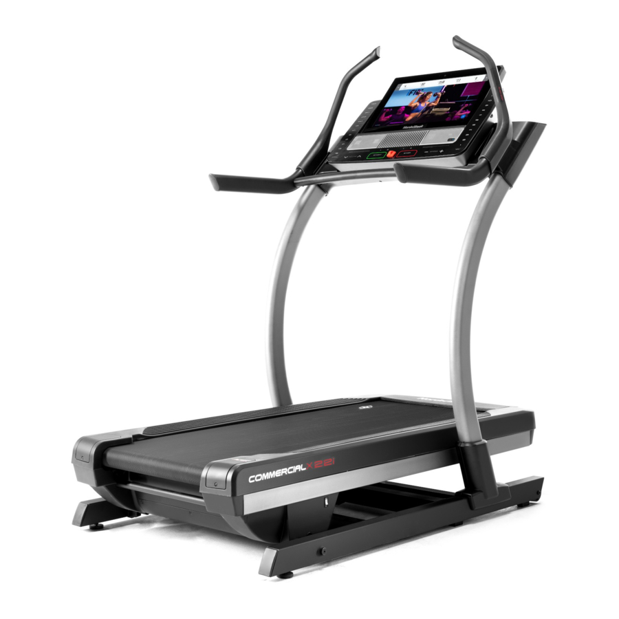
NordicTrack Commercial X22i User Manual
Hide thumbs
Also See for Commercial X22i:
- User manual (44 pages) ,
- User manual (36 pages) ,
- User manual (40 pages)
Table of Contents
Advertisement
Model No. NETL27719.0
Serial No.
Write the serial number in the space
above for reference.
CUSTOMER SERVICE
UNITED KINGDOM
Call: 0330 123 1045
From Ireland: 053 92 36102
Website: iconsupport.eu
E-mail: csuk@iconeurope.com
Write:
ICON Health & Fitness, Ltd.
Unit 4, Westgate Court
Silkwood Park
OSSETT
WF5 9TT
UNITED KINGDOM
AUSTRALIA
Call: 1800 993 770
E-mail: australiacc@iconfitness.com
Write:
ICON Health & Fitness
PO Box 635
WINSTON HILLS NSW 2153
AUSTRALIA
CAUTION
Read all precautions and
instructions in this manual before
using this equipment. Save this
manual for future reference.
Serial
Number
Decal
USER'S MANUAL
iconeurope.eu
Advertisement
Table of Contents

Related Manuals for NordicTrack Commercial X22i


Summary of Contents for NordicTrack Commercial X22i
- Page 1 Model No. NETL27719.0 USER’S MANUAL Serial No. Write the serial number in the space above for reference. Serial Number Decal CUSTOMER SERVICE UNITED KINGDOM Call: 0330 123 1045 From Ireland: 053 92 36102 Website: iconsupport.eu E-mail: csuk@iconeurope.com Write: ICON Health & Fitness, Ltd. Unit 4, Westgate Court Silkwood Park OSSETT...
-
Page 2: Table Of Contents
Apply the decal in the location shown. Note: The decals may not be shown at actual size. NORDICTRACK and IFIT are registered trademarks of ICON Health & Fitness, Inc. Google Maps is a trademark of Google LLC. The Bluetooth ®... -
Page 3: Important Precautions
IMPORTANT PRECAUTIONS WARNING: To reduce the risk of burns, fire, electric shock, or injury to persons, read all important precautions and instructions in this manual and all warnings on your incline trainer before using your incline trainer. ICON assumes no responsibility for personal injury or property damage sustained by or through the use of this product. - Page 4 20. Keep fingers, hair, and clothing away from be able to safely lift 20 kg (45 lbs.) to raise, the moving walking belt. lower, or move the incline trainer. 21. The incline trainer is capable of high speeds. 25. Never insert any object into any opening on Adjust the speed in small increments to the incline trainer.
-
Page 5: Before You Begin
COMMERCIAL X22I incline trainer. manual. To help us assist you, note the product model ® The COMMERCIAL X22I offers a selection of features number and serial number before contacting us. The designed to make your workouts at home more effec- model number and the location of the serial number tive and enjoyable. -
Page 6: Part Identification Chart
PART IDENTIFICATION CHART Use the drawings below to identify small parts used for assembly. The number in parentheses below each draw- ing is the key number of the part, from the PART LIST near the end of this manual. The number following the key number is the quantity used for assembly. -
Page 7: Assembly
ASSEMBLY • Assembly requires two persons. • To identify small parts, see page 6. • Place all parts in a cleared area and remove the • Assembly requires the following tools: packing materials. Do not dispose of the packing materials until you fi nish all assembly steps. the included hex keys •... - Page 8 2. Make sure that the power cord is unplugged. Remove the four 3/8" x 3 1/4" Screws (18) from the Base (74) (only one side is shown). Save the Screws. 3. Remove the four 3/8" x 2 3/4" Screws (22) from the Uprights (83).
- Page 9 4. Set the Uprights (83) on the Base (74). Make sure that the hole with the Upright Wire (75) is on the right side. Attach the right Upright (83) with two of the 3/8" x 3 1/4" Screws (18) and two of the 3/8" x 2 3/4"...
- Page 10 6. Remove the 5/16" x 1" Screws (87) and the 5/16" Star Washers (65) from the brackets (C) on the right and left handrail assemblies (D, E). With the help of a second person, position the right and left handrail assemblies (D, E) upside down as shown.
- Page 11 8. Slide the Right Inside Upright Cover (70) against the lower end of the right Upright (83). Then, press the Right Outside Upright Cover (71) against the Right Inside Upright Cover until it snaps into place. Make sure that the wires (G) are not pinched.
-
Page 12: The Chest Heart Rate Monitor
THE CHEST HEART RATE MONITOR HOW TO PUT ON THE HEART RATE MONITOR • Store the heart rate monitor in a warm, dry place. Do not store the heart rate monitor in a plastic bag or If the heart rate monitor looks like the one shown other container that may trap moisture. -
Page 13: How To Use The Incline Trainer
HOW TO USE THE INCLINE TRAINER HOW TO PLUG IN THE POWER CORD Follow the steps below to plug in the power cord. This product must be earthed. If it should malfunc- 1. Plug the indicated end of the power cord (A) into the tion or break down, earthing provides a path of least socket (B) on the Incline Trainer. - Page 14 CONSOLE DIAGRAM FEATURES OF THE CONSOLE In addition, the console features a selection of workouts. Each workout automatically controls the The advanced incline trainer console offers a selec- speed and incline of the incline trainer as it guides you tion of features designed to make your workouts more through an effective exercise session.
- Page 15 HOW TO TURN ON THE POWER HOW TO USE THE TOUCH SCREEN IMPORTANT: If the incline trainer has been The console features a tablet with a full-color touch exposed to cold temperatures, allow it to warm to screen. The following information will help you become room temperature before you turn on the power.
- Page 16 HOW TO SET UP THE CONSOLE 6. Calibrate the incline system. Before using the incline trainer for the first time, set up First, touch your name on the screen. Next, select the console. the settings main menu. Then, select the mainte- nance section, touch the Calibrate Incline button, 1.
- Page 17 HOW TO USE THE MANUAL MODE Note: If the walking belt is moving at a high speed and you adjust the incline below 0% or 1. Insert the key into the console. above 15.5%, the speed of the walking belt may automatically decrease.
- Page 18 • The average speed of the walking belt HOW TO USE A MAP WORKOUT • A track representing 400 m (1/4 mile) Note: To use a map workout, the console must be con- nected to a wireless network (see HOW TO USE THE If desired, adjust the volume by pressing the WIRELESS NETWORK MODE on page 23).
- Page 19 5. Monitor your progress with the display modes. If you make a mistake, you can use the Undo button on the left side of the screen. See step 5 on page 17. The screen will display the elevation and distance 6.
- Page 20 HOW TO USE A DISTANCE OR TIME WORKOUT 5. Select a distance or time workout that you have previously added to your schedule on iFit.com. Note: To use a distance or time workout, the console must be connected to a wireless network (see HOW Touch the calendar icon to download a distance or TO USE THE WIRELESS NETWORK MODE on time workout from your schedule.
- Page 21 HOW TO USE THE SLED PUSH FEATURE HOW TO CHANGE CONSOLE SETTINGS 1. Insert the key into the console. IMPORTANT: Some of the settings and features described may not be enabled. Occasionally, a See HOW TO TURN ON THE POWER on page 15. firmware update may cause your console to function slightly differently.
- Page 22 3. Customize the unit of measurement and other Note: Occasionally, a firmware update may cause settings. the console to function slightly differently. These updates are always designed to improve your To customize the unit of measurement, the time exercise experience. zone, or other settings, touch Equipment Settings, and then touch the desired settings.
- Page 23 HOW TO USE THE WIRELESS NETWORK MODE An information box will ask if you want to connect to the wireless network. Touch the Connect button The console features a wireless network mode that to connect to the network or touch the Cancel but- allows you to set up a wireless network connection.
- Page 24 HOW TO USE THE SOUND SYSTEM WITH A HOW TO USE THE SOUND SYSTEM WITH AN BLUETOOTH DEVICE AUDIO CABLE 1. Place or hold your Bluetooth-enabled device To play music or audio books through the console near the console. sound system while you exercise, plug a 3.5 mm male to 3.5 mm male audio cable (not included) into the 2.
-
Page 25: How To Move The Incline Trainer
HOW TO MOVE THE INCLINE TRAINER Before moving the incline trainer, insert the key Carefully roll the incline trainer on the wheels to the into the console (A), raise the incline to the maxi- desired location, and then lower it to the level position. mum incline level, remove the key, and unplug the CAUTION: To reduce the risk of injury, use extreme power cord. -
Page 26: Maintenance And Troubleshooting
MAINTENANCE AND TROUBLESHOOTING MAINTENANCE b. After the power cord has been plugged in, make sure that the key is inserted into the console. Regular maintenance is important for optimal performance and to reduce wear. Inspect and properly c. Check the power switch located on the incline tighten all parts each time the incline trainer is used. - Page 27 SYMPTOM: The console does not display speed SYMPTOM: The walking belt slows when walked on and distance correctly a. If an extension cord is needed, use only a 3-conduc- a. Remove the key from the console and UNPLUG tor, 14-gauge (2 mm²) cord that is no longer than THE POWER CORD.
- Page 28 SYMPTOM: The walking belt is not centred SYMPTOM: The walking belt slips when walked on between the foot rails a. First, adjust the incline to 40 percent. Next, remove The walking belt should be kept centred between the the key and UNPLUG THE POWER CORD. Using foot rails (D) (see the drawing below).
- Page 29 SYMPTOM: The console does not stay in place SYMPTOM: The displays of the console do not function properly a. If the console will not stay in the desired position because it is too loose, use a hex key to slightly a.
-
Page 30: Exercise Guidelines
EXERCISE GUIDELINES Burning Fat—To burn fat effectively, you must exer- WARNING: cise at a low intensity level for a sustained period of Before beginning this time. During the first few minutes of exercise, your or any exercise program, consult your physi- body uses carbohydrate calories for energy. - Page 31 SUGGESTED STRETCHES The correct form for several basic stretches is shown at the right. Move slowly as you stretch —never bounce. 1. Toe Touch Stretch Stand with your knees bent slightly and slowly bend forward from your hips. Allow your back and shoulders to relax as you reach down toward your toes as far as possible.
- Page 32 NOTES...
-
Page 33: Part List
PART LIST Model No. NETL27719.0 R0819A Key No. Qty. Description Key No. Qty. Description 3/8" x 5 1/2" Screw Cushion #8 x 1 1/4" Screw Base Wire 3/8" Star Washer Rubber Cushion #8 x 3/4" Pan Head Tek Screw Large Pivot Bushing #8 x 3/4"... - Page 34 Key No. Qty. Description Key No. Qty. Description #8 x 3/4" Machine Screw 5/16" Washer 5/16" x 3/4" Screw #8 Nut Reed Switch Filter Reed Switch Clip Magnet #8 x 3/4" Clip Screw Ferrite Box Motor Isolator – User’s Manual Motor Bushing Note: Specifications are subject to change without notice.
-
Page 35: Exploded Drawing
EXPLODED DRAWING A Model No. NETL27719.0 R0819A... - Page 36 EXPLODED DRAWING B Model No. NETL27719.0 R0819A...
- Page 37 EXPLODED DRAWING C Model No. NETL27719.0 R0819A...
- Page 38 EXPLODED DRAWING D Model No. NETL27719.0 R0819A...
- Page 39 EXPLODED DRAWING E Model No. NETL27719.0 R0819A...
-
Page 40: Ordering Replacement Parts
ORDERING REPLACEMENT PARTS To order replacement parts, please see the front cover of this manual. To help us assist you, be prepared to provide the following information when contacting us: • the model number and serial number of the product (see the front cover of this manual) •...