Table of Contents
Advertisement
Quick Links
nordictrack.com
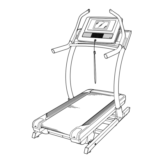
Model No. NTL22019.2
Serial No.
Write the serial number in the space
above for reference.
ACTIVATE YOUR
WARRANTY
To register your product and
activate your warranty today,
go to my.nordictrack.com
CUSTOMER CARE
For service at any time, go to
support.nordictrack.com.
Or call 1-800-TO-BE-FIT
(1-800-862-3348)
Mon.–Fri. 6 a.m.–6 p.m. MT
Sat. 8 a.m.–12 p.m. MT
Please do not contact the store.
CAUTION
Read all precautions and
instructions in this manual before
using this equipment. Save this
manual for future reference.
Serial
Number
Decal
USER'S MANUAL
Advertisement
Table of Contents

Related Manuals for NordicTrack NTL22019.2


Summary of Contents for NordicTrack NTL22019.2
- Page 1 USER’S MANUAL Model No. NTL22019.2 Serial No. Write the serial number in the space above for reference. Serial Number Decal ACTIVATE YOUR WARRANTY To register your product and activate your warranty today, go to my.nordictrack.com CUSTOMER CARE For service at any time, go to support.nordictrack.com.
-
Page 2: Table Of Contents
Note: The decals may not be shown at actual size. NORDICTRACK and IFIT are registered trademarks of ICON Health & Fitness, Inc. Google Maps is a trademark of Google LLC. The Bluetooth word mark and logos are registered trademarks of Bluetooth SIG, Inc. and are ®... -
Page 3: Important Precautions
Do not put the incline purchase a surge suppressor, see your local trainer in a garage or covered patio, or near NORDICTRACK dealer, call the telephone water. number on the front cover of this manual, or see your local electronics store. - Page 4 18. Read, understand, and test the emergency the power switch), and unplug the power cord stop procedure before using the incline when the incline trainer is not in use. trainer. (See HOW TO TURN ON THE POWER on page 17.) Always wear the clip while using 25.
- Page 6 STANDARD SERVICE PLANS...
-
Page 7: Before You Begin
BEFORE YOU BEGIN Thank you for selecting the revolutionary reading this manual, please see the front cover of this NORDICTRACK COMMERCIAL X11I Incline Trainer. manual. To help us assist you, note the product model ® The COMMERCIAL X11I Incline Trainer offers a selec- number and serial number before contacting us. -
Page 8: Part Identification Chart
PART IDENTIFICATION CHART Use the drawings below to identify small parts used for assembly. The number in parentheses below each draw- ing is the key number of the part, from the PART LIST near the end of this manual. The number following the key number is the quantity used for assembly. -
Page 9: Assembly
If there is an oily substance on the incline trainer, wipe it off with a soft cloth and a mild, non-abra- sive cleaner. 1. Go to my.nordictrack.com on your computer and register your product. • documents your ownership • activates your warranty •... - Page 10 2. Make sure that the power cord is unplugged. Remove the four 3/8" x 3 1/4" Screws (18) from the Base (74) (only one side is shown). Save the Screws. 3. Remove the four 3/8" x 2 3/4" Screws (22) from the Uprights (83).
- Page 11 4. Set the Uprights (83) on the Base (74). Make sure that the hole with the Upright Wire (75) is on the right side. Attach the right Upright (83) with two of the 3/8" x 3 1/4" Screws (18) and two of the 3/8" x 2 3/4"...
- Page 12 6. Remove the 5/16" x 1" Screws (87) and the 5/16" Star Washers (65) from the brackets (C) on the right and left handrail assemblies (D, E). With the help of a second person, position the right and left handrail assemblies (D, E) upside down as shown.
- Page 13 8. Slide the Right Inside Upright Cover (70) against the lower end of the right Upright (83). Then, press the Right Outside Upright Cover (71) against the Right Inside Upright Cover until it snaps into place. Make sure that the wires (G) are not pinched.
-
Page 14: The Chest Heart Rate Monitor
THE CHEST HEART RATE MONITOR HOW TO PUT ON THE HEART RATE MONITOR • Store the heart rate monitor in a warm, dry place. Do not store the heart rate monitor in a plastic bag or If the heart rate monitor looks like the one shown other container that may trap moisture. -
Page 15: How To Use The Incline Trainer
HOW TO USE THE INCLINE TRAINER HOW TO CONNECT THE POWER CORD The outlet must be on a nominal 120-volt circuit capable of carrying 15 or more amps. To avoid Use a Surge Suppressor overloading the circuit, do not plug other electrical devices, except for low-power devices such as cell Your incline trainer, like other electronic equipment, phone chargers, into the surge suppressor or into... - Page 16 CONSOLE DIAGRAM FEATURES OF THE CONSOLE In addition, the console features a selection of workouts. Each workout automatically controls the The advanced incline trainer console offers a selec- speed and incline of the incline trainer as it guides you tion of features designed to make your workouts more through an effective exercise session.
- Page 17 HOW TO TURN ON THE POWER HOW TO USE THE TOUCH SCREEN IMPORTANT: If the incline trainer has been The console features a tablet with a full-color touch exposed to cold temperatures, allow it to warm to screen. The following information will help you become room temperature before you turn on the power.
- Page 18 HOW TO SET UP THE CONSOLE 6. Calibrate the incline system. Before using the incline trainer for the first time, set up First, touch your name or Hello on the screen. the console. Next, select the settings main menu. Then, select the maintenance section, touch Calibrate Incline, 1.
- Page 19 HOW TO USE THE MANUAL MODE Note: If the walking belt is moving at a high speed and you adjust the incline below 0% or 1. Insert the key into the console. above 15.5%, the speed of the walking belt may automatically decrease.
- Page 20 HOW TO USE A MAP WORKOUT • The average speed of the walking belt • A track representing 1/4 mile (400 m) Note: To use a map workout, the console must be con- nected to a wireless network (see HOW TO USE THE If desired, adjust the volume by pressing the WIRELESS NETWORK MODE on page 25).
- Page 21 5. Monitor your progress with the display modes. If you make a mistake, you can use the Undo button on the left side of the screen. See step 5 on page 19. The screen will display the elevation and distance 6.
- Page 22 HOW TO USE A DISTANCE OR TIME WORKOUT 5. Select a distance or time workout that you have previously added to your schedule on iFit.com. Note: To use a distance or time workout, the console must be connected to a wireless network (see HOW Touch the calendar icon to download a distance or TO USE THE WIRELESS NETWORK MODE on time workout from your schedule.
- Page 23 HOW TO USE THE SLED PUSH FEATURE HOW TO CHANGE CONSOLE SETTINGS 1. Insert the key into the console. IMPORTANT: Some of the settings and features described may not be enabled. Occasionally, a See HOW TO TURN ON THE POWER on firmware update may cause your console to function page 17.
- Page 24 3. Customize the unit of measurement and other Note: Occasionally, a firmware update may cause settings. the console to function slightly differently. These updates are always designed to improve your To customize the unit of measurement, the time exercise experience. zone, or other settings, touch Equipment Settings, and then touch the desired settings.
- Page 25 HOW TO USE THE WIRELESS NETWORK MODE An information box will ask if you want to connect to the wireless network. Touch the Connect button The console features a wireless network mode that to connect to the network or touch the Cancel but- allows you to set up a wireless network connection.
- Page 26 HOW TO USE THE SOUND SYSTEM WITH A HOW TO USE THE SOUND SYSTEM WITH AN BLUETOOTH DEVICE AUDIO CABLE 1. Place or hold your Bluetooth-enabled device To play music or audio books through the console near the console. sound system while you exercise, plug a 3.5 mm male to 3.5 mm male audio cable (not included) into the jack 2.
-
Page 27: How To Move The Incline Trainer
HOW TO MOVE THE INCLINE TRAINER Before moving the incline trainer, insert the key Carefully roll the incline trainer on the wheels to the into the console (A), adjust the incline to the maxi- desired location, and then lower it to the level position. mum incline level, remove the key, and unplug the CAUTION: To reduce the risk of injury, use extreme power cord. -
Page 28: Maintenance And Troubleshooting
MAINTENANCE AND TROUBLESHOOTING MAINTENANCE b. After the power cord has been plugged in, make sure that the key is inserted into the console. Regular maintenance is important for optimal performance and to reduce wear. Inspect and properly c. Check the power switch located on the incline tighten all parts each time the incline trainer is used. - Page 29 SYMPTOM: The walking belt slows when walked on SYMPTOM: The walking belt is off-center or slips when walked on a. Use only a surge suppressor that meets all of the a. If the walking belt is off-center, first adjust the specifications described on page 15.
- Page 30 SYMPTOM: The incline trainer will not connect to SYMPTOM: The displays of the console do not the wireless network function properly a. Make sure that the wireless settings on the console a. If the console does not boot up properly, or are correct (see page 25).
-
Page 31: Exercise Guidelines
EXERCISE GUIDELINES Burning Fat—To burn fat effectively, you must exer- WARNING: cise at a low intensity level for a sustained period of Before beginning this time. During the first few minutes of exercise, your or any exercise program, consult your physi- body uses carbohydrate calories for energy. - Page 32 SUGGESTED STRETCHES The correct form for several basic stretches is shown at the right. Move slowly as you stretch —never bounce. 1. Toe Touch Stretch Stand with your knees bent slightly and slowly bend forward from your hips. Allow your back and shoulders to relax as you reach down toward your toes as far as possible.
-
Page 33: Part List
PART LIST Model No. NTL22019.2 R0520A Key No. Qty. Description Key No. Qty. Description 3/8" x 5 1/2" Screw Cushion Cap #8 x 1 1/4" Screw Spring 3/8" Star Washer Cushion #8 x 3/4" Pan Head Tek Screw Base Wire #8 x 3/4"... - Page 34 Key No. Qty. Description Key No. Qty. Description Right Handrail Left Handrail Bottom 1/4" Flat Washer Right Handrail Bottom – User’s Manual 3/8" x 3/4" Screw Note: Specifications are subject to change without notice. For information about ordering replacement parts, see the back cover of this manual.
-
Page 35: Exploded Drawing
EXPLODED DRAWING A Model No. NTL22019.2 R0520A... - Page 36 EXPLODED DRAWING B Model No. NTL22019.2 R0520A...
- Page 37 EXPLODED DRAWING C Model No. NTL22019.2 R0520A...
- Page 38 EXPLODED DRAWING D Model No. NTL22019.2 R0520A...
- Page 39 EXPLODED DRAWING E Model No. NTL22019.2 R0520A...