NordicTrack Commercial X22i User Manual
Hide thumbs
Also See for Commercial X22i:
- User manual (44 pages) ,
- User manual (39 pages) ,
- User manual (40 pages)
Table of Contents
Advertisement
nordictrack.com
Model No. NTL29221.2
Serial No.
Write the serial number in the space
above for reference.
ACTIVATE YOUR
WARRANTY
To register your product and
activate your warranty today,
go to my.nordictrack.com
CUSTOMER CARE
For service at any time, go to
support.nordictrack.com.
Or call 1-800-TO-BE-FIT
(1-800-862-3348)
Mon.–Fri. 6 a.m.–6 p.m. MT
Sat. 8 a.m.–12 p.m. MT
Please do not contact the store.
CAUTION
Read all precautions and
instructions in this manual before
using this equipment. Save this
manual for future reference.
Serial
Number
Decal
USER'S MANUAL
Advertisement
Table of Contents

Related Manuals for NordicTrack Commercial X22i


Summary of Contents for NordicTrack Commercial X22i
- Page 1 Serial Number Decal ACTIVATE YOUR WARRANTY To register your product and activate your warranty today, go to my.nordictrack.com CUSTOMER CARE For service at any time, go to support.nordictrack.com. Or call 1-800-TO-BE-FIT (1-800-862-3348) Mon.–Fri. 6 a.m.–6 p.m. MT Sat. 8 a.m.–12 p.m. MT Please do not contact the store.
-
Page 2: Table Of Contents
Apply the decal in the location shown. Note: The decals may not be shown at actual size. NORDICTRACK and IFIT are registered trademarks of ICON Health & Fitness, Inc. Google Maps is a trademark of Google LLC. The Bluetooth ®... -
Page 3: Important Precautions
14. To commercial, rental, or institutional setting. purchase a surge suppressor, see your local NORDICTRACK dealer, call the telephone 6. Keep the incline trainer indoors, away from number on the front cover of this manual, or moisture and dust. - Page 4 18. Read, understand, and test the emergency 24. Do not attempt to move the incline trainer stop procedure before using the incline until it is properly assembled. (See trainer. (See HOW TO TURN ON THE POWER ASSEMBLY on page 9, and HOW TO MOVE on page 16.) Always wear the clip while using THE INCLINE TRAINER on page 26.) You must the incline trainer.
- Page 6 STANDARD SERVICE PLANS...
-
Page 7: Before You Begin
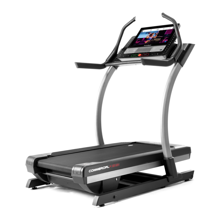
COMMERCIAL X22I. The manual. To help us assist you, note the product model ® COMMERCIAL X22I offers a selection of features number and serial number before contacting us. The designed to make your workouts at home more effec- model number and the location of the serial number tive and enjoyable. -
Page 8: Part Identification Chart
PART IDENTIFICATION CHART Use the drawings below to identify small parts used for assembly. The number in parentheses below each draw- ing is the key number of the part, from the PART LIST near the end of this manual. The number following the key number is the quantity used for assembly. -
Page 9: Assembly
If there is an oily substance on the incline trainer, wipe it off with a soft cloth and a mild, non-abra- sive cleaner. 1. Go to my.nordictrack.com on your computer and register your product. • documents your ownership • activates your warranty •... - Page 10 2. Make sure that the power cord is unplugged. Remove the four 3/8" x 3 1/4" Screws (18) from the Base (74) (only one side is shown). Save the Screws. 3. Remove the four 3/8" x 2 3/4" Screws (22) from the Uprights (83).
- Page 11 4. Set the Uprights (83) on the Base (74). Make sure that the hole with the Upright Wire (75) is on the right side. Attach the right Upright (83) with two of the 3/8" x 3 1/4" Screws (18) and two of the 3/8" x 2 3/4"...
- Page 12 6. Remove the 5/16" x 1" Screws (87) and the 5/16" Star Washers (57) from the brackets (C) on the right and left handrail assemblies (D, E). With the help of a second person, position the right and left handrail assemblies (D, E) upside down as shown.
- Page 13 8. Slide the Right Inside Upright Cover (70) against the lower end of the right Upright (83). Then, press the Right Outside Upright Cover (71) against the Right Inside Upright Cover until it snaps into place. Make sure that the wires (G) are not pinched, pulled tightly, or resting across the indicated screw (H).
-
Page 14: How To Use The Incline Trainer
HOW TO USE THE INCLINE TRAINER HOW TO CONNECT THE POWER CORD The outlet must be on a nominal 120-volt circuit capable of carrying 15 or more amps. To avoid Use a Surge Suppressor overloading the circuit, do not plug other electrical devices, except for low-power devices such as cell Your incline trainer, like other electronic equipment, phone chargers, into the surge suppressor or into... - Page 15 CONSOLE DIAGRAM FEATURES OF THE CONSOLE When you use the manual mode, you can change the speed and incline of the incline trainer with the touch The advanced incline trainer console offers a selec- of a button. As you exercise, the console will display tion of features designed to make your workouts more instant exercise feedback.
- Page 16 HOW TO TURN ON THE POWER HOW TO USE THE TOUCH SCREEN IMPORTANT: If the incline trainer has been The console features a tablet with a full-color touch exposed to cold temperatures, allow it to warm to screen. The following information will help you become room temperature before you turn on the power.
- Page 17 HOW TO SET UP THE CONSOLE 5. Calibrate the incline system. Before using the incline trainer for the first time, set up First, touch your name or Hello on the screen. the console. Next, select the settings main menu. Then, select the maintenance section, touch Calibrate Incline, 1.
- Page 18 HOW TO USE THE MANUAL MODE Note: If the walking belt is moving at a high speed and you adjust the incline below 0% or 1. Insert the key into the console. above 15.5%, the speed of the walking belt may automatically decrease.
- Page 19 7. When you are finished exercising, remove the 3. Select a map workout. key from the console. To select a map workout, touch the desired button Step onto the foot rails and press the Stop button on the screen. Note: The featured map workouts on the console or tap on the screen.
- Page 20 HOW TO USE A DRAW YOUR OWN MAP 4. Save your workout. WORKOUT Touch Save New Workout on the screen. If desired, Note: To use a draw your own map workout, the change the title of the workout or add a description, console must be connected to a wireless network (see and then press the >...
- Page 21 HOW TO USE A DISTANCE OR TIME WORKOUT 6. Start the workout. Note: To use a distance or time workout, the console See step 4 on page 19. Note: During a distance or must be connected to a wireless network (see HOW time workout, the display will not show a map.
- Page 22 HOW TO CHANGE CONSOLE SETTINGS 4. View machine information. IMPORTANT: Some of the settings and features Touch Equipment Info, and then touch Machine described may not be enabled. Occasionally, a Info to view information about your incline trainer. firmware update may cause your console to function slightly differently.
- Page 23 HOW TO CONNECT TO A WIRELESS NETWORK An information box will ask if you want to connect to the wireless network. Touch the Connect button The console is Wi-Fi enabled, allowing you to set up a to connect to the network or touch the Cancel but- wireless network connection.
- Page 24 HOW TO USE THE SOUND SYSTEM THE OPTIONAL HEART RATE MONITOR To play music or audio books through the console Whether your sound system while you exercise, you can connect goal is to a personal audio device to the console with an audio burn fat or to cable, or you can connect wirelessly if your device is strengthen your...
-
Page 25: Fcc Information
FCC INFORMATION This equipment has been tested and found to comply with the limits for a Class B digital device, pursuant to Part 15 of the FCC Rules. These limits are designed to provide reasonable protection against harmful interference in a residential installation. This equipment generates, uses, and can radiate radio frequency energy and, if not installed and used in accordance with the instructions, may cause harmful interference to radio communications. -
Page 26: How To Move The Incline Trainer
HOW TO MOVE THE INCLINE TRAINER Before moving the incline trainer, insert the key Carefully roll the incline trainer on the wheels to the into the console (A), raise the incline to the maxi- desired location, and then lower it to the level position. mum incline level, remove the key, and unplug the CAUTION: To reduce the risk of injury, use extreme power cord. -
Page 27: Maintenance And Troubleshooting
MAINTENANCE AND TROUBLESHOOTING MAINTENANCE SYMPTOM: The power turns off during use Regular maintenance is important for optimal a. Check the power switch (see drawing c). If the performance and to reduce wear. Inspect and properly switch has tripped, wait for five minutes and then tighten all parts each time the incline trainer is used. - Page 28 SYMPTOM: The walking belt slows when walked on SYMPTOM: The walking belt is off-center or slips when walked on a. Use only a surge suppressor that meets all of the specifications described on page 14. a. If the walking belt is off-center, first adjust the incline to 40 percent.
- Page 29 SYMPTOM: The incline trainer will not connect to SYMPTOM: The displays of the console do not the wireless network function properly a. Make sure that the wireless settings on the console a. If the console does not boot up properly, or are correct (see page 23).
-
Page 30: Exercise Guidelines
EXERCISE GUIDELINES Aerobic Exercise—If your goal is to strengthen your WARNING: cardiovascular system, you must perform aerobic Before beginning this exercise, which is activity that requires large amounts or any exercise program, consult your physi- of oxygen for prolonged periods of time. For aerobic cian. - Page 31 SUGGESTED STRETCHES The correct form for several basic stretches is shown at the right. Move slowly as you stretch —never bounce. 1. Toe Touch Stretch Stand with your knees bent slightly and slowly bend forward from your hips. Allow your back and shoulders to relax as you reach down toward your toes as far as possible.
- Page 32 NOTES...
-
Page 33: Part List
PART LIST Model No. NTL29221.2 R1120A Key No. Qty. Description Key No. Qty. Description 3/8" x 5 1/2" Screw Belt #8 x 1 1/4" Screw Front Hood Cover 3/8" Star Washer Front Hood #8 x 3/4" Pan Head Tek Screw Cushion Cap #8 x 3/4"... - Page 34 Key No. Qty. Description Key No. Qty. Description Left Tray 3/8" x 3/4" Screw Console Base #8 x 3/4" Machine Screw Console M3 x 12mm Screw Right Tray Power Supply #8 x 1" Screw Incline Motor Controller #8 x 3/4" Console Screw Standoff Right Handrail Left Handrail Bottom...
-
Page 35: Exploded Drawing
EXPLODED DRAWING A Model No. NTL29221.2 R1120A... - Page 36 EXPLODED DRAWING B Model No. NTL29221.2 R1120A...
- Page 37 EXPLODED DRAWING C Model No. NTL29221.2 R1120A...
- Page 38 EXPLODED DRAWING D Model No. NTL29221.2 R1120A...
- Page 39 EXPLODED DRAWING E Model No. NTL29221.2 R1120A...
-
Page 40: Ordering Replacement Parts
ORDERING REPLACEMENT PARTS To order replacement parts, please see the front cover of this manual. To help us assist you, be prepared to provide the following information when contacting us: • the model number and serial number of the product (see the front cover of this manual) •...