SATO S84-ex Operator's Manual
Hide thumbs
Also See for S84-ex:
- Programming reference manual (452 pages) ,
- Operator's manual (380 pages) ,
- Configuration manual (2 pages)
Table of Contents
Advertisement
Quick Links
Advertisement
Table of Contents
Troubleshooting

Related Manuals for SATO S84-ex


Summary of Contents for SATO S84-ex
- Page 1 Operator Manual For printer model:...
- Page 2 Specifications and contents in this document are subject to change without notice. Be sure to perform a virus check on the USB memory or SD card before connecting it to the product. SATO Corporation shall not be held responsible for any product malfunctions caused by a virus spread via USB memory or SD card.
-
Page 3: Table Of Contents
2.2 Installation Space....................26 2.2.1 Front View (S84-ex/S86-ex) ..................26 2.2.2 Rear View (S84-ex/S86-ex) ..................27 2.2.3 Media Dispensed View (S84-ex) ................27 2.2.4 Top View (S84-ex) ....................28 2.2.5 Media Dispensed View (S86-ex) ................29 2.2.6 Top View (S86-ex) ....................30 2.3 Installing the Product onto a Support Structure/Applicator ...... - Page 4 4.2.17 Test Print Mode ....................190 4.2.18 Default Setting Mode ................... 193 4.2.19 Download Mode....................196 4.2.20 Upload Mode ....................... 201 4.2.21 Hidden Setting Mode ................... 203 4.2.22 Wireless LAN Certificate Download Mode............204 4.2.23 Site Survey Mode ....................206 S84-ex/S86-ex Operator Manual...
- Page 5 6.1.4 More about the Media Stop Position ..............264 6.1.5 Limitation on Base Reference Point Adjustment ........... 265 6.2 Adjusting the Print Quality................266 6.2.1 Adjusting the Print Darkness ................. 266 6.2.2 Adjusting the Print Speed ..................267 S84-ex/S86-ex Operator Manual...
- Page 6 8.4 Troubleshooting Table ................... 312 8.4.1 No Power/Nothing on the Screen ................312 8.4.2 Cannot Feed the Media ..................312 8.4.3 Can Feed the Media but Cannot Print ..............313 8.4.4 Bad Print Quality....................314 8.4.5 Incorrect Print Position ..................314 S84-ex/S86-ex Operator Manual...
- Page 7 9.6 Notification Function ..................345 9.7 Media Motion of the Product Operation ............347 9.7.1 Feed Motion......................347 9.7.2 Paper End......................347 9.7.3 Sensor Error ......................351 9.7.4 Ribbon Error ......................352 9.8 Print Speed and Media Size ................353 S84-ex/S86-ex Operator Manual...
- Page 8 9.12.1 USB Interface ...................... 379 9.12.2 LAN Ethernet Interface ..................380 9.12.3 RS-232C Interface....................382 9.12.4 IEEE1284 Interface ..................... 384 9.12.5 External Signal Interface (EXT) ................386 9.12.6 Bluetooth Interface ....................399 9.12.7 Wireless LAN Interface..................400 S84-ex/S86-ex Operator Manual...
-
Page 9: Before You Start
• New designed sensor cover with nonstick surface that can be easily removed and cleaned without any tools. • Easily upload/download data to/from an SD card or USB memory, or by using the SATO All-In-One Tool application. • Supports remote product setting through the SATO All-In-One Tool application or a Web browser. - Page 10 Do not set on an unstable area your SATO reseller or technical support. • Do not set the product on an unstable Using the product in one of these...
- Page 11 Doing so could result in a fire or electric immediately power it off, and contact shock. your SATO reseller or technical support. • Do not splash water on the power cord or Using the product in this condition could get it wet. Doing so could result in result in a fire or electric shock.
- Page 12 If a child accidentally drinks the fluid, product. Doing so could result in a fire or immediately consult with a physician. electric shock. Ask your SATO reseller or technical support to conduct internal inspections, adjustments, and repairs. S84-ex/S86-ex Operator Manual...
- Page 13 Operator Manual does not contain this procedure, avoid trying to replace it on Do not place the product in areas with high your own terms, and contact your SATO humidity reseller or technical support. • Do not place this product in an area with •...
- Page 14 (the combination of media and ribbon), and the product settings (the print speed, the print darkness, etc.). Please sufficiently test the product in your usage environment, and use it with the optimal combination. If anything is unclear, or if you have any questions, contact your SATO reseller or technical support center. S84-ex/S86-ex Operator Manual...
- Page 15 • Remove the certificate label (serial number seal) affixed to this product. Use of this product near microwave and/or other wireless LAN equipment, or where static electricity or radio interference is present, may shorten the communication distance, or even disable communication. S84-ex/S86-ex Operator Manual...
- Page 16 Diese Einrichtung kann im Wohnbereich Funkstörungen verursachen. In diesem Fall kann vom Betreiber verlangt werden, angemessene Maßnahmen durchzuführen. Das Gerät ist nicht für die Benutzung im unmittelbaren Gesichtsfeld am Bildschirmarbeitsplatz vorgesehen. Um störende Reflexionen am Bildschirmarbeitsplatz zu vermeiden, darf dieses Produkt nicht im unmittelbaren Gesichtsfeld platziert werden. S84-ex/S86-ex Operator Manual...
- Page 17 Before You Start (Pb) (Hg) (Cd) (Cr6+) (PBB) (PBDE) ABS PC SJ/T 11364 GB/T 26572 GB/T 26572 2006 2 28 SJ/T11364 S84-ex/S86-ex Operator Manual...
- Page 18 Access the following site and select your country from the list. Check the information on the shown page. www.satoworldwide.com/service-and-support.aspx Warranty Period for Consumables For information on the warranty period for print heads and platen rollers, refer to the SATO Global Warranty Program. www.satoworldwide.com/global-warranty-program.aspx...
-
Page 19: Basic Information
Basic Information 1.1 Checking the Bundled Accessories After unpacking the product, make sure that you have all the bundled accessories. If there are missing items, contact the SATO reseller where you purchased the product. User documents (Quick guide, Safety instructions, Global Warranty Program leaflet, etc.) -
Page 20: Product Orientation
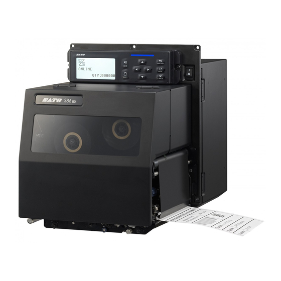
Europe/Asia: Left Hand Europe/Asia: Right Hand Note The pictures in this manual show the S84-ex (Americas: Standard/Right Hand, Europe/Asia: Left Hand), unless otherwise stated. When using the right hand (Americas: Opposite/Left Hand, Europe/Asia: Right Hand) model, the picture on the right shows a symmetrical opposite view of your product. -
Page 21: Parts Identification Of The Product
1.3 Parts Identification of the Product 1.3.1 Front View Operator panel Top cover Power (I/O) switch Press this switch to power on (I) or power off (O) the product. Media discharge outlet S84-ex/S86-ex Operator Manual... -
Page 22: Rear View
Be sure to perform a virus check on the SD card AC input terminal before connecting it to the product. SATO Supplies power to the product through the Corporation shall not be held responsible for any inserted power cord. -
Page 23: Internal View
Pressure roller release tab CAUTION Used to release the pressure plate. Be sure to perform a virus check on the USB memory before connecting it to the product. SATO Ribbon rewind spindle Corporation shall not be held responsible for any ... -
Page 24: Parts On The Operator Panel
Returns to the setting mode menu from the product is in normal mode. setting screens. ENTER button Enter the setting mode menu when the product is in offline mode. Confirm the selected item or setting value when the product is in setting mode. S84-ex/S86-ex Operator Manual... -
Page 25: Led Indicator
Error detected (For example, when a machine error is detected) Error detected (For example, when the ribbon runs out) Flashes at intervals of two seconds. Blue and Error detected (For example, when a communication error has occurred) Alternately flashes blue and red. S84-ex/S86-ex Operator Manual... - Page 26 1 Basic Information This page is intentionally left blank. S84-ex/S86-ex Operator Manual...
-
Page 27: Installing The Product
• A location with high temperature and humidity. • A dusty location. • A location exposed to direct sunlight. • A location with a lot of electrical noise. • A location with a large fluctuation in power. S84-ex/S86-ex Operator Manual... -
Page 28: Installation Space
The illustrations in this section show the product from different angles, providing dimensions and spatial requirements. 2.2.1 Front View (S84-ex/S86-ex) 245 mm (9.6”) 117.5 mm 117.5 mm (4.6”) (4.6”) -
Page 29: Mm (1.7")
5 positions 11 mm (0.4”) 223 mm (8.8”) 11 mm (0.4”) Americas: Standard/Right Hand Europe/Asia: Left Hand 2.2.3 Media Dispensed View (S84-ex) 43 mm (1.7”) Americas: Standard/Right Hand Europe/Asia: Left Hand 150 mm (5.9”) 131 mm (5.15”) 189 mm (7.4”) -
Page 30: Top View (S84-Ex)
2 Installing the Product 2.2.4 Top View (S84-ex) 150 mm (5.9”) 174 mm (6.85”) 223 mm (8.8”) 174 mm (6.85”) 150 mm (5.9”) 10 mm (0.4”) Americas: Standard/Right Hand 230 mm (9.1”) Europe/Asia: Left Hand S84-ex/S86-ex Operator Manual... - Page 31 2 Installing the Product 2.2.5 Media Dispensed View (S86-ex) 43 mm (1.7”) Americas: Standard/Right Hand Europe/Asia: Left Hand 150 mm (5.9”) 131 mm (5.15”) 243 mm (9.6”) S84-ex/S86-ex Operator Manual...
-
Page 32: Americas: Standard/Right Hand
2 Installing the Product 2.2.6 Top View (S86-ex) 150 mm (5.9”) 174 mm (6.85”) 223 mm (8.8”) 174 mm (6.85”) 150 mm (5.9”) 10 mm (0.4”) Americas: Standard/Right Hand Europe/Asia: Left Hand 230 mm (9.1”) S84-ex/S86-ex Operator Manual... -
Page 33: Installing The Product Onto A Support Structure/Applicator
If you do not install the product correctly, it could fall out of the support structure. This may cause injury. The picture below shows the installation of the product onto the support structure. Note This picture is for an instructional display purpose only and is not to be interpreted as a precise example. S84-ex/S86-ex Operator Manual... -
Page 34: Connecting The Interface Cable
Connect the product to a host computer with one or more of the available interface connections. Use a cable that is compatible with the standard of the interface board as stated in Section 9.12 Interface Specifications. Check the orientation of the connector before you make the connection. S84-ex/S86-ex Operator Manual... -
Page 35: Interface Settings
* You cannot select the interface that has already been set for the DATA PORT. Note The main port and sub port cannot simultaneously use the same interface. Data port - SBPL command (Print data) - Product status Sub port - Product status S84-ex/S86-ex Operator Manual... -
Page 36: Interface Combination
LAN adapter, the configured interface setting is changed from WLAN to USB. When USB is configured as the data port or sub port, but the wireless LAN adapter is connected, the configured interface setting is changed from USB to WLAN. S84-ex/S86-ex Operator Manual... -
Page 37: Connecting The Power Cord
AC 100-240 V, 50-60 Hz. If your local voltage is not in the stated range, contact your SATO reseller or technical support center. *The shape of the power plug varies depending on the region in which it was purchased. -
Page 38: Power On/Off The Product
Make sure that the product is in offline mode before you power off. If ONLINE shows on the screen, press the LINE button to change to offline mode. Press the power switch on the operator panel to “O” position. S84-ex/S86-ex Operator Manual... -
Page 39: Installing Optional Memory Storage
Contact your SATO reseller or service center for the recommended SD card or USB memory. CAUTION Be sure to perform a virus check on the USB memory or SD card before connecting it to the product. SATO Corporation shall not be held responsible for any product malfunctions caused by a virus spread via USB memory or SD card. -
Page 40: Removing The Optional Sd Card
Open the top cover. Insert the optional USB memory into the USB connector (Type A) on the front of the product. Contact your SATO reseller for the recommended USB memory. Close the top cover. To remove the USB memory from the... -
Page 41: Loading The Ribbon And Media
If there is a mark on the media, the ink is coated on the outer side of the ribbon. The ink is coated on the inner side. (Face-in ribbon) The ink is coated on the outer side. (Face-out ribbon) S84-ex/S86-ex Operator Manual... -
Page 42: Loading The Ribbon
Note You can also refer to the routing path sticker located on the inner side of the top cover. Open the top cover . CAUTION Open the top cover fully to prevent accidental drop of the cover. S84-ex/S86-ex Operator Manual... - Page 43 Make sure that the ink side of the ribbon is facing down when passing it below the print head. Load an empty ribbon core onto the ribbon rewind spindle . Insert the core all the way in. S84-ex/S86-ex Operator Manual...
- Page 44 If the media is already loaded, turn the head lock lever counterclockwise to lock the print head. If the media is not loaded, continue with Section 3.5 Loading Media. Close the top cover. S84-ex/S86-ex Operator Manual...
-
Page 45: Removing The Ribbon
. Pull to remove the empty core from the ribbon supply spindle . You can use this empty core again when you load a new ribbon roll. Load this empty core onto the ribbon rewind spindle. S84-ex/S86-ex Operator Manual... -
Page 46: Usable Media
The position of the gap sensor is adjustable. You can adjust the gap sensor position in the following range. S84-ex: 5 mm to 66 mm (0.2” to 2.6”) measured from the product’s center frame. S86-ex: 5 mm to 81 mm (0.2” to 3.2”) measured from the product’s center frame. -
Page 47: Loading Media
When loading the media, make sure that the print side is facing Platen roller Label Feed roller and media sensor assembly. Pressure Media shaft roller Label Liner Media shaft Open the top cover. CAUTION Open the top cover fully to prevent accidental drop of the cover. S84-ex/S86-ex Operator Manual... - Page 48 Push the media until the innermost edge of the media lightly touches the product’s center frame. Pull the label out from the discharge outlet. Remove about 30 cm (11.8”) of labels from the liner . S84-ex/S86-ex Operator Manual...
- Page 49 Refer to Section 4.2.17 Test Print Mode for details on how to perform a test print. CAUTION When closing the top cover, be careful not to pinch your fingers. S84-ex/S86-ex Operator Manual...
-
Page 50: Loading Media Without Using Dispenser
Refer to Section 4.2.17 Test Print Mode for details on how to perform a test print. CAUTION When closing the top cover, be careful not to pinch your fingers. S84-ex/S86-ex Operator Manual... -
Page 51: Display And Operation
Shows when the product is in test print mode and hex dump print mode. Shows when the product is in download mode. Shows when the product is in upload mode. Shows when the product is in memory mode. S84-ex/S86-ex Operator Manual... -
Page 52: Operation And Configuration
Always shows when the product is not connected. Shows when the product is not connected to an access point. Not used • Bluetooth connection status Icon Description Shows when Bluetooth is connected. Shows when Bluetooth is disconnected. S84-ex/S86-ex Operator Manual... - Page 53 Shows when a label “near end” is detected. Shows when a command error is detected. Shows when a receive buffer “near full” is detected. Shows when print head damage is detected. Shows when an incompatible print head is detected. S84-ex/S86-ex Operator Manual...
- Page 54 • These icons do not show when the product is in an error mode. • These icons do not show when the trace mode is enabled. • These icons do not show when the ESC+IM command (for specifying LCD display) is in use. S84-ex/S86-ex Operator Manual...
-
Page 55: Setting Mode Menu And Icons
* Shows only if you have installed the optional RFID kit and enabled the RFID mode. The product enters the product information mode. The product enters the loaded emulation mode. * Shows only if you have loaded with the selected emulation firmware module. S84-ex/S86-ex Operator Manual... -
Page 56: Error Display And Icons
Receive buffer over is detected. Item No. error or BCC error is detected. Memory card is not accessible or there is no free space in the memory card. Writing to the ROM failed or kanji data error is detected. S84-ex/S86-ex Operator Manual... -
Page 57: Setting Display
Save the setting and go to the next screen. Returns to the previous screen Setting item Setting contents Valid arrow Select an item using the without saving display display buttons display the setting. buttons. S84-ex/S86-ex Operator Manual... - Page 58 Returns to the previous screen without saving Setting item Setting contents Valid arrow Move the cursor Change the value of the setting. display display buttons the highlighted cursor using the display buttons. using the buttons. S84-ex/S86-ex Operator Manual...
-
Page 59: Operating Modes
Hex Dump Mode • RFID User Mode • Information Mode • Test Print Mode • Default Setting Mode • Download Mode • Upload Mode • Hidden Setting Mode • Wireless LAN Certificate Download Mode • Site Survey Mode S84-ex/S86-ex Operator Manual... - Page 60 * Shows only if you have button RFID User installed the optional RFID RFID user Mode kit and enabled RFID mode. mode button button Information Information Mode mode More operations are shown on the next page. S84-ex/S86-ex Operator Manual...
- Page 61 Power on Download Mode mode Upload Power on Upload Mode mode Power on Hidden Hidden setting Setting Mode mode Wireless LAN Power on WLAN certificate Certificate download mode Download Mode Site Survey Power on Site survey Mode mode S84-ex/S86-ex Operator Manual...
-
Page 62: Online Mode/Pause Mode/Offline Mode
Enters the setting mode menu. Cancel the print job. Shows the remaining Enters online Feed a Adjust the Press simultaneously print job. mode or pause piece of display for one second to enter mode. media. brightness. adjustment mode. S84-ex/S86-ex Operator Manual... -
Page 63: Adjusting The Display Brightness
The buzzer volume icon is shown on the top right corner of the screen. Pressing the button will cycle through the volume level and the buzzer will beep according to the volume. S84-ex/S86-ex Operator Manual... -
Page 64: Canceling The Print Job
• ALL: Cancel all the print jobs in product’s memory. Press the ENTER button to confirm. CANCEL PRINT JOB COMPLETED shows and three beeps will sound. The product will then enter offline mode. The selected print jobs will be cleared from memory. S84-ex/S86-ex Operator Manual... -
Page 65: Adjustment Mode
'-' to move the stop position in the feed direction. The setting value is adjustable by 0.25 mm (0.01”) regardless of the print resolution. The setting range is from -3.75 mm (-0.15”) to +3.75 mm (+0.15”). S84-ex/S86-ex Operator Manual... - Page 66 CANCEL button before pressing the ENTER button will not save the adjustment. Perform a test print after completing the adjustments to make sure that the settings are correct. Refer to Section 4.2.17 Test Print Mode for details. S84-ex/S86-ex Operator Manual...
-
Page 67: Work Shift Setting Mode
Select the work shift number to store the work shift setting. You can select the work shift number from 1 to 3. Note If you select EXIT and press the ENTER button, the product returns to the online screen. S84-ex/S86-ex Operator Manual... - Page 68 The number of characters you can enter depends on the character size set in the HOW MANY CHR? screen. Press the buttons to shift the cursor and press the buttons to set the character. Press the ENTER button to save the work shift name. S84-ex/S86-ex Operator Manual...
-
Page 69: Simple Standalone Mode
Select NO + button button Shows only if there is variable data. button button button Select YES button button Shows only if there is sequential data. button button button button button button S84-ex/S86-ex Operator Manual... - Page 70 4 Operation and Configuration CAUTION Be sure to perform a virus check on the USB memory or SD card before connecting it to the product. SATO Corporation shall not be held responsible for any product malfunctions caused by a virus spread via USB memory or SD card.
- Page 71 Three beeps will sound if the product fails to copy the received data. The product returns to the STANDALONE MODE screen. SAVE COMPLETED. This screen shows when the received data is saved to a specified file. Press the ENTER button to return to the STANDALONE MODE screen. S84-ex/S86-ex Operator Manual...
- Page 72 DIGIT is the digit number of the selected cursor. The screen may be decimal or hexadecimal according to the read data. The maximum number of DIGIT is 99. Note Shows only if there is sequential data. S84-ex/S86-ex Operator Manual...
- Page 73 4 Operation and Configuration OUTPUT LABEL This screen allows you to specify the print number. Move the cursor using the buttons, change the value using buttons and then press the ENTER button. S84-ex/S86-ex Operator Manual...
-
Page 74: Setting Mode Menu
The product changes to the setting mode menu. Select the setting mode using the buttons. The selected setting mode shows on the screen and the icon is highlighted by inverting its colors. Press the ENTER button to enter the selected mode. S84-ex/S86-ex Operator Manual... - Page 75 The functions of the buttons in the setting mode menu are shown as below. Enters offline mode. Enters the selected setting mode. Enters offline mode. Selected Selected icon Navigate to Valid arrow buttons setting highlighted select the for selection. mode. with inverted setting mode. colors. S84-ex/S86-ex Operator Manual...
-
Page 76: User Mode
Shows only if the PASSWORD input is enabled button button button/ button button button button button button button button button button button button button button button button button button Shows only if GB18030 is selected button button Proceed to S84-ex/S86-ex Operator Manual... - Page 77 The setting values of the adjustment mode are shown. • PITCH: Shows the print position offset value. • OFFSET: Shows the stop position offset value. • DARKNESS: Shows the darkness setting value. You can change these values in Adjustment Mode Test Print Mode. S84-ex/S86-ex Operator Manual...
- Page 78 4 Operation and Configuration PRINT SPEED The setting range varies depending on the model. • S84-ex (203 dpi): 4 to 16 ips (inches/sec) • S86-ex (203 dpi): 4 to 14 ips (inches/sec) • S84-ex (305 dpi): 4 to 14 ips (inches/sec) •...
- Page 79 • CHANGE HEAD: Notify when to perform replacement of the print head. • CHANGE BELT (G): Notify when to perform replacement of the gear box timing belt. • CHANGE BELT (R): Notify when to perform replacement of the ribbon timing belt. S84-ex/S86-ex Operator Manual...
- Page 80 CHANGE TIMING BELT (GEAR BOX) Set the notification distance for changing the gear box timing belt. The setting range is from 000 to 300 km. Note The notification function will be disabled if the distance is set to 0. S84-ex/S86-ex Operator Manual...
- Page 81 The notification function will be disabled if the distance is set to 0. SETTING FINISH? Confirm to complete the setting. • YES: Returns to the user mode screen. • NO: Returns to the NOTICE FUNCTION screen to select an item. S84-ex/S86-ex Operator Manual...
-
Page 82: Interface Mode
Select “USB”/ “LAN”/ “RS-232C”/ “IEEE1284” /“Bluetooth”/“WLAN”+ button Setting contents vary depending on the interface. To the USB setting To the IEEE1284 setting To the LAN/WLAN setting To the Bluetooth setting To the RS-232C setting Proceed to S84-ex/S86-ex Operator Manual... - Page 83 Select DISABLE + button Shows only for LAN button interface if SNTP Select IPv6 FUNCTION is enabled. button Select IPv4 button button button button button button (IPv4) button (IPv6) button button button Proceed to S84-ex/S86-ex Operator Manual...
- Page 84 SNMP FUNCTION is enabled. button SNMP TRAP SET+ button SNMP SETTING+ button button button button button To the SNMP v1/v2c button To the SNMP v3 Proceed to NO + button YES + button button button button button S84-ex/S86-ex Operator Manual...
- Page 85 INTERFACE MODE menu. button button button button button button NONE + button button MD5/SHA-1 + button button button button NONE + button DES/AES + button button button button button S84-ex/S86-ex Operator Manual...
- Page 86 TYPE SELECT is set to SNMPv1/SNMPv2c. to SNMPv3. button button button button NONE+ (SNMPv1/v2c) button button (SNMPv3) MD5/SHA-1 + button button button button NONE+ button DES/AES + button button button IPv6+ button IPv4+ button button button button button S84-ex/S86-ex Operator Manual...
- Page 87 • NO: Enter the IGNORE CR/LF screen. PORT SELECT Select the port used for the connected interface. • DATA PORT: For receiving various SBPL commands and executing print operations. • SUB PORT: For monitoring the product status and connecting to external devices. S84-ex/S86-ex Operator Manual...
- Page 88 • The setting will be effective after you power on the product again. IGNORE CR/LF Ignore or acknowledge the CR/LF code of the received data. • YES: Ignore the CR/LF code. • NO: Do not ignore the CR/LF code. Note Shows only if the DATA PORT is selected. S84-ex/S86-ex Operator Manual...
- Page 89 Shows only if LAN interface is selected and the SNTP function is enabled. NTP IPv4 ADDRESS Set the IPv4 address for NTP server. The setting range is from 0.0.0.0 to 255.255.255.255. Note Shows only if LAN interface is selected and the SNTP function is enabled. S84-ex/S86-ex Operator Manual...
- Page 90 Set the SNMP function. • ENABLE: Enables the SNMP function and goes to “SNMP setting select” screen. • DISABLE: Disables the SNMP function and goes to “Interface select screen. Note Shows only if LAN or wireless LAN interface is selected. S84-ex/S86-ex Operator Manual...
- Page 91 Select the trap number of SNMP from 1 to 3. • TRAP [1] • TRAP [2] • TRAP [3] TRAP TYPE SELECT Select SNMP trap type. • SNMPv1 • SNMPv2c • SNMPv3 Note The setting will be effective after you power on the product again. S84-ex/S86-ex Operator Manual...
- Page 92 Note • Up to 32 alphanumeric characters and symbols (from 20H to 7EH) can be set. • Specify “ ” to input a space. • The setting will be effective after you power on the product again. S84-ex/S86-ex Operator Manual...
- Page 93 • The setting will be effective after you power on the product again. PRIVACY PROTOCOL Select SNMP privacy protocol. The options are as follows: • NONE • DES • AES Note The setting will be effective after you power on the product again. S84-ex/S86-ex Operator Manual...
- Page 94 Writing possible OID are sysContact, sysName, and sysLocation. TRAP Set the SNMP trap. • ENABLE: Allows the SNMP trap. • DISABLE: Does not allow the SNMP trap. Note The setting will be effective after you power on the product again. S84-ex/S86-ex Operator Manual...
- Page 95 • The setting will be effective after you power on the product again. AUTH PROTOCOL Select SNMP trap authentication protocol. The options are as follows: • NONE • MD5 • SHA-1 Note The setting will be effective after you power on the product again. S84-ex/S86-ex Operator Manual...
- Page 96 • Up to 32 alphanumeric characters and symbols (from 20H to 7EH) can be set. • Specify “ ” to input a space. • The setting will be effective after you power on the product again. S84-ex/S86-ex Operator Manual...
- Page 97 • ENABLE: Enable the FTP function. • DISABLE: Disable the FTP function. Note • Shows only if the LAN or wireless LAN interface is selected. • The setting will be effective after you power on the product again. S84-ex/S86-ex Operator Manual...
- Page 98 • ENABLE: Enable the TELNET function. • DISABLE: Disable the TELNET function. Note • Shows only if the LAN or wireless LAN interface is selected. • The setting will be effective after you power on the product again. S84-ex/S86-ex Operator Manual...
- Page 99 • STATUS5: When selected, the product will proceed to the ITEM NO. CHECK screen. ITEM NO. CHECK Set the item number check function. • ENABLE: Enable the item number check function. • DISABLE: Disable the item number check function. Note Shows only if PROTOCOL is set to STATUS5. S84-ex/S86-ex Operator Manual...
- Page 100 4 Operation and Configuration BCC CHECK Set the BCC check function. • ENABLE: Enable the BCC check function. • DISABLE: Disable the BCC check function. Note Shows only if PROTOCOL is set to STATUS5. S84-ex/S86-ex Operator Manual...
- Page 101 (DHCP DISABLE) (DHCP ENABLE) button Shows only if LAN interface is selected. Select “DHCP” or “AUTO” + button button (“DHCP” or “AUTO” selected) Select “MANUAL” button button button button button button button button button Proceed to S84-ex/S86-ex Operator Manual...
- Page 102 Shows only if wireless LAN interface is selected. button button button button button button button button Shows only if STATUS5 is selected. button button button button Shows only if STATUS4 is selected. button button button Proceed to S84-ex/S86-ex Operator Manual...
- Page 103 Set the IPv4 gateway address. The setting range is from 0.0.0.0 to 255.255.255.255. The default value is 000.000.000.000 for LAN and 192.168.001.002 for WLAN. Note The setting will be effective after you power on the product again. S84-ex/S86-ex Operator Manual...
- Page 104 Shows only if LAN interface is selected and “MANUAL” is selected at “IPv6 RESOLUTION” screen. DEFAULT ROUTER Set the default router of IPv6. Note Shows only if LAN interface is selected and “MANUAL” is selected at “IPv6 RESOLUTION” screen. S84-ex/S86-ex Operator Manual...
- Page 105 You can enter a maximum of thirty-two characters including alphabet (upper case and lower case), numbers and symbols. Note • Shows only if wireless LAN interface is selected. • The setting will be effective after you power on the product again. S84-ex/S86-ex Operator Manual...
- Page 106 Shows only if PROTOCOL is set to STATUS5. BCC CHECK Set the BCC check function. • ENABLE: Enable the BCC check function. • DISABLE: Disable the BCC check function. Note Shows only if PROTOCOL is set to STATUS5. S84-ex/S86-ex Operator Manual...
- Page 107 • ENQ: Returns a status after receiving a Status Request (ENQ), which has been sent from the host. • CYCLE: Returns a status from the product to the host at an interval of 500 ms. Note Shows only if PROTOCOL is set to STATUS4. S84-ex/S86-ex Operator Manual...
- Page 108 00H 00H 00H 1CH 00H 00H 1CH Status5 ENABLE DISABLE (Default) ENQ (05H) prefix: 4 bytes prefix: 0 byte response 00H 00H 00H 16H Note This setting does not have to be changed when using the S84-ex/S86-ex printer driver. S84-ex/S86-ex Operator Manual...
- Page 109 Select READY/BUSY or XON/XOFF button Select STATUS2, STATUS3 or STATUS4 button Select STATUS5 button button button Shows only if Shows only if READY/BUSY STATUS5 is or XON/XOFF is selected selected button button button button Proceed to S84-ex/S86-ex Operator Manual...
- Page 110 Set the RS-232C stop bit. The following options are available: • 1BIT • 2BIT Note • Shows only if the RS-232C interface is selected. • The setting will be effective after you power on the product again. S84-ex/S86-ex Operator Manual...
- Page 111 The setting will be effective after you power on the product again. ITEM NO. CHECK Set the item number check function. • ENABLE: Enable the item number check function. • DISABLE: Disable the item number check function. Note Shows only if PROTOCOL is set to STATUS5. S84-ex/S86-ex Operator Manual...
- Page 112 Shows only if PROTOCOL is set to STATUS5. RECEIVE BUFFER Set the receive buffer type. • MULTI: Multiple receive buffers. • 1ITEM: A single receive buffer. Note Shows only if PROTOCOL is set to READY/BUSY or XON/XOFF. S84-ex/S86-ex Operator Manual...
- Page 113 INTERFACE MODE menu. button button Shows only if STATUS5 is selected button button button button Shows only if STATUS4 is selected button button Shows only if RECEIVE BUFFER is set to 1ITEM. button Proceed to S84-ex/S86-ex Operator Manual...
- Page 114 • DISABLE: Disable the BCC check function. Note Shows only if PROTOCOL is set to STATUS5. RECEIVE BUFFER Set the receive buffer type. • MULTI: Multiple receive buffers. • 1ITEM: A single receive buffer. Note Shows only if PROTOCOL is set to STATUS4. S84-ex/S86-ex Operator Manual...
- Page 115 Set the width of the IEEE1284 ACK signal. The setting range is from 00.5 µs to 12.0 µs, and is adjustable in 0.1 µs steps. Note Shows only if the IEEE1284 interface is selected and RECEIVE BUFFER is set to 1ITEM. S84-ex/S86-ex Operator Manual...
- Page 116 INTERFACE MODE menu. button button button button button button button button Shows only if ENABLE is selected button button button button button button button button button button button Proceed to S84-ex/S86-ex Operator Manual...
- Page 117 • ENABLE: Enable the Bluetooth detection response. • DISABLE: Disable the Bluetooth detection response. Note • Shows only if the Bluetooth interface is selected. • The setting will be effective after you power on the product again. S84-ex/S86-ex Operator Manual...
- Page 118 • Shows only if the Bluetooth interface is selected. • You cannot set the PSW value if it is greater than the PSI value. • The setting will be effective after you power on the product again. S84-ex/S86-ex Operator Manual...
- Page 119 The following options are available: • STATUS3 • STATUS4 CRC CHECK Set the CRC check function. • ENABLE: Enable the CRC check function. • DISABLE: Disable the CRC check function. Note Shows only if the Bluetooth interface is selected. S84-ex/S86-ex Operator Manual...
-
Page 120: Memory Mode
CAUTION Be sure to perform a virus check on the USB memory or SD card before connecting it to the product. SATO Corporation shall not be held responsible for any product malfunctions caused by a virus spread via USB memory or SD card. - Page 121 Select “FORMAT” CONTENT” + button button Select “MEMORY SIZE” button button button button button button button button button button Select “NO” button Select “YES” button or Select “NO” + button button Select “YES” button button button button S84-ex/S86-ex Operator Manual...
- Page 122 Select whether or not to set the memory storage allocation for use with the Memory card command <CC>. • YES: Proceed to change the storage allocation for the memory slot. • NO: No change to the memory slot. Note Refer to the Programming Reference for details on the command. S84-ex/S86-ex Operator Manual...
- Page 123 Select the memory you want to perform the settings. The following options are available: • SD CARD • USB MEMORY • ROM Note Shows only if MEMORY MODE is set to MEMORY SIZE, STORED CONTENTS or FORMAT. S84-ex/S86-ex Operator Manual...
- Page 124 • FORMAT • GRAPHIC • BMP FILE • TTF FILE MEMORY INFORMATION Shows the number of files and total size of the selected type of information registered in the memory. The maximum number of files is 999. S84-ex/S86-ex Operator Manual...
- Page 125 ENTER button, the screen returns to PLEASE SELECT MEMORY. MEMORY FORMAT Select whether or not to format the memory. • YES: Format the memory. • NO: Do not format the memory. Note If you select NO, the screen returns to MEMORY CARD MODE. S84-ex/S86-ex Operator Manual...
- Page 126 The following options are available: • SD CARD • USB MEMORY Note • Shows only if MEMORY MODE is set to SETTING SAVE. • The setting information of the wireless LAN is saved only if the wireless LAN is connected. S84-ex/S86-ex Operator Manual...
- Page 127 After three beeps, the screen returns to MEMORY CARD MODE. SELECT MEMORY ORIGIN Select the memory to copy the setting information. The following options are available: • SD CARD • USB MEMORY Note Shows only if MEMORY MODE is set to SETTING UPLOAD. S84-ex/S86-ex Operator Manual...
- Page 128 PRINTER SETTING COMPLETED Shows when the setting information has been uploaded to the product. Note • Three beeps will sound when the upload is completed. • The setting will be effective after you power on the product again. S84-ex/S86-ex Operator Manual...
-
Page 129: Service Mode
PASSWORD input is enabled button SERVICE MODE Select one from the three service setting modes. • SENSOR LEVEL: Adjust the sensor level. • SETTING: Set the various function settings of the product. • COUNTER CLEAR: Clear various counter value. S84-ex/S86-ex Operator Manual... - Page 130 When I-MARK is selected When GAP is selected button button button Calibration succeed. Calibration failed. button button button Select RETRY button button button Select EXIT CALIBRATION button button button button S84-ex/S86-ex Operator Manual...
- Page 131 This screen shows the instruction to place the media for I-mark sensor adjustment. Shows only if GAP is selected in the SENSOR SELECT screen. After placing the media, press the ENTER button to start the automatic sensor adjustment. S84-ex/S86-ex Operator Manual...
- Page 132 Shows the current level (Reception) of the I-mark sensor on the upper part of the screen. This offset determines how soon the sensor will respond to an incoming I-mark. The adjustment range is from 0 to 127 and is shown on the bottom line of the screen. S84-ex/S86-ex Operator Manual...
- Page 133 0.1 V) Note • The slice level is set automatically by the firmware when the value is set to 0.0 V. • In the case of automatic calculation, the calculated value will be shown automatically after printing. S84-ex/S86-ex Operator Manual...
- Page 134 REPRINT, or CONTINUOUS PRINT is set to ENABLE. button button button button button button Shows only if EXT 9PIN SELECT is set to MODE3. button button Shows only if you have installed the optional RFID kit and enabled the RFID mode. button Proceed to S84-ex/S86-ex Operator Manual...
- Page 135 Shows for the thermal transfer model only. button button button button Select ON button button button Select OFF button button button button Shows for the S86-ex series models only. 203 dpi: NORMAL/M8460Se/M8485Se 305 dpi: NORMAL/M8465Se button Proceed to S84-ex/S86-ex Operator Manual...
- Page 136 Shows only if SAVE PRINT LOG is set to ENABLE. button button button button button button Shows only for the thermal transfer model. button button button Proceed to S84-ex/S86-ex Operator Manual...
- Page 137 305 dpi Shows for the S86-ex series models only. button button button button Select YES + button and when there are changes in printer settings. button button Select NO + button button Waiting to be powered off. S84-ex/S86-ex Operator Manual...
- Page 138 Enable or disable the reprint function using the FEED button. If this function is enabled, you can reprint the last print job by pressing the FEED button in online mode. • YES: Enable the reprint function. • NO: Disable the reprint function. S84-ex/S86-ex Operator Manual...
- Page 139 ONLINE pin: Outputs the signal whether if the product is in online or offline mode. PRN READY pin: Outputs the signal whether if the product has remaining print data or not. Note Refer to the Timing Chart of the EXT Output Signal (Online) for details. S84-ex/S86-ex Operator Manual...
- Page 140 Shows only if you have installed the optional RFID kit and enabled the RFID mode. BACKFEED SPEED Specify the backfeed speed. • FAST: Set to a speed of six inches per second. • NORMAL: Set to a speed of four inches per second. S84-ex/S86-ex Operator Manual...
- Page 141 Enable or disable the detection of the ribbon near end. • ENABLE: Detect and notify when the ribbon is about to run out. • DISABLE: Do not detect the ribbon near end. Note Shows for the thermal transfer model only. S84-ex/S86-ex Operator Manual...
- Page 142 • ON: Keep the compatibility with the product operation of existing models. • OFF: Disable the compatibility with the product operation of existing models. Note For details on the legacy command support, refer to Section 9.3 About Legacy Command Support. S84-ex/S86-ex Operator Manual...
- Page 143 Section 9.3.2 Compatible Mode - Print Head Width (only for S86-ex) for details on the affected items. COMPATIBLE MODE DARKNESS Enable or disable the system command Print Darkness <#E>. • ENABLE: Enable you to execute the Print Darkness <#E>. • DISABLE: Ignore the Print Darkness <#E>. S84-ex/S86-ex Operator Manual...
- Page 144 • Shows only if COMPATIBLE MODE DARKNESS is set to ENABLE. • This table explains that the system accepts the legacy Print Darkness setting command and does not guarantee that the printed darkness of the succeeding model will be the same as the older model. S84-ex/S86-ex Operator Manual...
- Page 145 The setting range varies depending on the following models: Model Name Setting Range Default (mm) Value (mm) S84-ex (203 dpi) 0 - 2500 2500 S84-ex (305 dpi) 0 - 1500 1500 S84-ex (609 dpi) 0 - 400...
- Page 146 CAUTION Be sure to perform a virus check on the USB memory or SD card before connecting it to the product. SATO Corporation shall not be held responsible for any product malfunctions caused by a virus spread via USB memory or SD card.
- Page 147 The product may not operate with the FAST setting, depending on the operating environment. FEED OFFSET Set the feed distance in LINERLESS mode. The setting range is from 000 to 250 mm. Note Shows only if PRINTER TYPE in ADVANCED MODE is set to LINERLESS. S84-ex/S86-ex Operator Manual...
- Page 148 Enable or disable the Plug and play function of the product. • ENABLE: Enable the Plug and play function. • DISABLE: Disable the Plug and play function. Note This function will affect the IEEE1284 interface connectivity because it uses the DEVICE ID response of the IEEE1284. S84-ex/S86-ex Operator Manual...
- Page 149 • If “0000ms” is selected, the product sends an ENQ response with no delay. • If status 4 is set as the cyclic response mode, the product sends an ENQ response with no delay for cycle response or ENQ command. S84-ex/S86-ex Operator Manual...
- Page 150 The printable maximum size of the TrueType font varies depending on the following settings: GB18030 BIG5 KSX1001 Available TrueType font size (MB) 10.6 10.7 10.8 11.7 Note When the product tries to print a TrueType font that is bigger than the maximum size, a command error occurs. S84-ex/S86-ex Operator Manual...
- Page 151 The product can be initialized to this setting at a later time. Refer to Section 4.2.18 Default Setting Mode. DEFAULT SETTING COMPLETED Shows when the product settings have been saved completely. Note The setting will be effective after you power on the product again. S84-ex/S86-ex Operator Manual...
- Page 152 • BELT (RIBBON): Clear the counter of ribbon timing belt. CONFIRM COUNTER CLEAR HEAD Select whether to clear the head counter or not. • YES: Clear the head counter. • NO: Does not clear the head counter. S84-ex/S86-ex Operator Manual...
- Page 153 CONFIRM COUNTER CLEAR BELT (R) Select whether to clear the counter of ribbon timing belt or not. • YES: Clear the counter of ribbon timing belt. • NO: Does not clear the counter of ribbon timing belt. S84-ex/S86-ex Operator Manual...
-
Page 154: Advanced Mode
PASSWORD input is enabled button button DISPENSER + button button (CONTINUOUS or LINERLESS) button button button (CONTINUOUS) button (DISPENSER) button button (DISPENSER) button (LINERLESS) ENABLE + DISABLE + button (CONTINUOUS) button (LINERLESS) (CONTINUOUS) (DISPENSER) button button Proceed to S84-ex/S86-ex Operator Manual... - Page 155 “CHECK PAGE”. button button YES + button NO + Shows only if CONTINUOUS is DISABLE + selected. button button button button button button button button Shows only if EXTERNAL REPRINT is enabled. button Proceed to Proceed to S84-ex/S86-ex Operator Manual...
- Page 156 “MODE3” is selected in “EXT 9PIN SELECT” in Service mode. button button Power on the product again . YES + NO + NO + button button YES + Power on the product again. button Proceed to S84-ex/S86-ex Operator Manual...
- Page 157 12 dots/mm and legacy command support is selected. button button Shows only if the button YES + calendar IC is installed button button NO + button button NO + YES + button button button button button button button button Proceed to S84-ex/S86-ex Operator Manual...
- Page 158 Select 0 button button button (0) button button (other than 0) button button button button Shows only if button PAPER END is GAP. button button button button button button Returns to the ADVANCED button MODE screen. S84-ex/S86-ex Operator Manual...
- Page 159 • DIRECT: Print using direct thermal paper. PITCH SENSOR Enable or disable the pitch sensor. • ENABLE: Enable the pitch sensor. • DISABLE: Disable the pitch sensor. Note Shows only if PRINTER TYPE is set to CONTINUOUS. S84-ex/S86-ex Operator Manual...
- Page 160 CAUTION Head check is a reference for checking for a filament disconnection of the print head. This function does not guarantee barcode readability. Note Shows only if the head check function is enabled. S84-ex/S86-ex Operator Manual...
- Page 161 • NO: Proceed to the ZERO SLASH screen. EXTERNAL SIGNAL Enable or disable the external signal (EXT) function. • ENABLE: Enable the external signal (EXT) function. • DISABLE: Disable the external signal (EXT) function. Note Shows only if PRINTER TYPE is set to CONTINUOUS. S84-ex/S86-ex Operator Manual...
- Page 162 The product will not reprint if a command error occurs. CONTINUOUS PRINT Set the reprint function by the print start signal (PRIN) from an external signal. • ENABLE: Enable the continuous print when no print quantity is remaining. • DISABLE: Disable the continuous print. S84-ex/S86-ex Operator Manual...
- Page 163 Shows only if EXTERNAL REPRINT is enabled. I/O SIGNAL SETTING Select whether or not to set the pin number for the input/output signal. • YES: Proceed to the INPUT SIGNAL screen. • NO: Proceed to the I/O SIGNALS INITIALIZE screen. S84-ex/S86-ex Operator Manual...
- Page 164 MODE3 is selected. Note • DISPENSE IN and HOME POS. are available only if CONTROLED is selected in BACKFEED MOTION. • For details, refer to Section 9.5 Input/Output Signal of the External Signal. S84-ex/S86-ex Operator Manual...
- Page 165 Refer to the default value of the pin number in INPUT SIGNAL/OUTPUT SIGNAL. INITIALIZED SETTING This screen shows that the pin number for the input/output signal has been initialized. Power on the product again to make the setting effective. S84-ex/S86-ex Operator Manual...
- Page 166 ‘-’ to move to the right side of the product (when facing the front of the product). The setting range varies depending on the following models: Model Name V (dot) H (dot) S84-ex (203 dpi) ±0-9999 ±0-832 S84-ex (305 dpi) ±0-9999 ±0-1248 S84-ex (609 dpi) ±0-9999...
- Page 167 Toggle the head dot density from 12 dots/mm to 6 dots/mm and vice versa. The following options are available: • 100: Approximately four inches. Effective for S84-ex only. • 150: Approximately six inches. Effective for S84-ex and S86-ex. • 300: Approximately twelve inches. Effective for S84-ex and S86-ex. Note...
- Page 168 MAY, F-JUNE, G-JULY, H-AUGUST, J-SEPTEMBER, K-OCTOBER, L-NOVEMBER, M-DECEMBER. Select the month using the buttons, select the month code using buttons, then press the ENTER button to confirm the month code. Note Shows only if YES is selected in the SET CALENDAR screen. S84-ex/S86-ex Operator Manual...
- Page 169 • STANDARD: Use a standard code. • NON-STANDARD: Use a non-standard code. Note To set the non-standard code, send the user download command <LD> in normal mode. For more details on the <LD> command, refer to the Programming Reference. S84-ex/S86-ex Operator Manual...
- Page 170 MODE SELECT Set the communication command mode for analysis. • XML: Use for supporting Oracle and SAP mode. • SBPL: Use SBPL (SATO Barcode Printer Language) for the printer commands. Note The setting will be effective after you power on the product again.
- Page 171 Specify the width of the label for rotation. The setting range varies depending on the following models: Model Name Setting Range Default Value Step (dot) (dot) S84-ex (203 dpi) 0000-0832 0832 S84-ex (305 dpi) 0000-1248 1248 S84-ex (609 dpi) 0000-2496...
- Page 172 LABEL SIZE ADJ HEIGHT Specify the height of the label for rotation. The setting range varies depending on the following models: Model Name Setting Range Default Value (dot) (dot) S84-ex (203 dpi) 00000-20000 20000 S84-ex (305 dpi) 00000-18000 18000 S84-ex (609 dpi)
- Page 173 • OFF: The LED indicator is always off. ERROR INDICATION Set the LCD backlight for indicating an error. • NONE: No change to the LCD backlight. • ON: The LCD backlight lights orange. • BLINKS: The LCD backlight flashes orange. S84-ex/S86-ex Operator Manual...
-
Page 174: Hex Dump Mode
CAUTION Be sure to perform a virus check on the USB memory or SD card before connecting it to the product. SATO Corporation shall not be held responsible for any product malfunctions caused by a virus spread via USB memory or SD card. - Page 175 For internal buffer Hex dump icon is shown if INTERNAL printing and internal buffer data DATA is selected. printing, the screen automatically icon is shown if RECEIVE changes to normal mode after BUFFER is selected. issuing the media. S84-ex/S86-ex Operator Manual...
- Page 176 • SAVE: Save and print the received data. HEX DUMP Set the print width of the hex dump. • NORMAL: Print the received data with sixteen bytes in one line. • HALF: Print the received data with eight bytes in one line. S84-ex/S86-ex Operator Manual...
- Page 177 ONLINE This screen shows an online status icon if RECEIVE DATA is selected. HEX DUMP PRINT HEX DUMP SAVE OFFLINE This screen shows an offline status icon if RECEIVE DATA or INTERNAL DATA is selected. S84-ex/S86-ex Operator Manual...
- Page 178 This screen shows while the product is transmitting the “SEND BACK DATA”. SEND BACK DATA COMPLETED This screen shows that the product has completed the transmission of “SEND BACK DATA”. Note The product returns to the HEX DUMP MODE screen after three beeps. S84-ex/S86-ex Operator Manual...
-
Page 179: Rfid User Mode
USER MODE menu. button button Shows only if the PASSWORD input is enabled button button button button button button button button button button button button button Select LEVEL button Select PULSE button button button button button Proceed to S84-ex/S86-ex Operator Manual... - Page 180 USER MODE menu. button When reading is When reading collected error occurs Select YES button Select CONTINUE button Select RETRY button or Select NO button button button button button button button button button button button button button button S84-ex/S86-ex Operator Manual...
- Page 181 • YES: Proceed to clear the RFID write numbers (SUCCESS, FAILURE and TOTAL). • NO: Do not clear the RFID counter. Note The total accumulated number of RFID write in the RFID LIFE COUNT is not cleared. S84-ex/S86-ex Operator Manual...
- Page 182 Select whether or not to print a slash on a tag when an RFID tag error occurred. • YES: Prints a slash at the time of RFID tag error. • NO: Do not print a slash at the time of RFID tag error. Only RFID TAG ERROR is printed. S84-ex/S86-ex Operator Manual...
- Page 183 Press the buttons to select the reading area from EPC, TID, USER and PC. • YES: The product reads and shows the data. • NO: Do not read the data and proceed to the next screen. S84-ex/S86-ex Operator Manual...
- Page 184 The setting range is from 0 to 240 mm. To release this function, set the value to 0 mm. WRITE POWER Set the write power of the antenna, referring to the “S84-ex UHF Inlay Placement & Configuration Table” in the S84-ex UHF RFID Configuration Guide.
- Page 185 4 Operation and Configuration READ POWER Set the read power of the antenna, referring to the “S84-ex UHF Inlay Placement & Configuration Table” in the S84-ex UHF RFID Configuration Guide. The measurement unit is in dBm, and it is adjustable with 0.1 dBm.
-
Page 186: Information Mode
Shows only if the PASSWORD input is enabled button button button button button Select Select Select Select LIFE Select HEAD DISPENSE BELT BELT button button button (GEAR BOX) (RIBBON) Select button button button Select NONE button button Proceed to S84-ex/S86-ex Operator Manual... - Page 187 Manual setting: DISABLE Auto settings (not confirmed): ----- button Auto settings (confirmed): IEEE1284/RS-232C/LAN/ USB/WLAN/Bluetooth Version Shows the model name and firmware version of this product. SERIAL NO. Shows the serial number of the control board in this product. S84-ex/S86-ex Operator Manual...
- Page 188 The default selection is NONE. LIFE COUNTER Shows the life count value saved in the product. HEAD COUNTER Shows the head count value saved in the product. DISPENSE COUNTER Shows the dispense count value saved in the product. S84-ex/S86-ex Operator Manual...
- Page 189 LAN IPv6 ADDRESS Shows the IPv6 address of the LAN. Note If the IP address is not acquired from DHCP, it will be shown as “----:----:----:----:----:----:----:----”. LAN IPv6 ROUTER Shows the IPv6 router information for the LAN. S84-ex/S86-ex Operator Manual...
- Page 190 • When the product fails to acquire the IP address or DHCP is disabled, the static IP address will be shown. WLAN MAC ADDRESS Shows the MAC address of the wireless LAN. Note This screen shows only if a wireless LAN unit is installed. BD ADDRESS Shows the BD address. S84-ex/S86-ex Operator Manual...
- Page 191 Shows the interface auto detection status. Note • “-----” shows when the interface is not detected. • DISABLE shows that the INTERFACE AUTO SELECT function is disabled (manual setting). • IEEE1284, RS-232C, LAN, USB, WLAN or Bluetooth shows the detected interface. S84-ex/S86-ex Operator Manual...
-
Page 192: Test Print Mode
Make sure that the EXTERNAL SIGNAL is set to DISABLE before perform test print. • When RFID mode is enabled, RFID related information is printed on the second page of the CONFIGURATION test print. S84-ex/S86-ex Operator Manual... - Page 193 Select the width of the test print from LARGE or SMALL. The available width varies depending on the following models: Model Name LARGE (cm) SMALL (cm) S84-ex S86-ex Note Shows only if TEST PRINT MODE is set to FACTORY or WLAN. S84-ex/S86-ex Operator Manual...
- Page 194 ENTER button to start the test print. TEST PRINT PRESS ENTER KEY The test print is in progress. Press the ENTER button while printing to pause the test print operation. Press the ENTER button again to continue. S84-ex/S86-ex Operator Manual...
-
Page 195: Default Setting Mode
Select the item to be initialized. • PRINTER SETTING: Initialize the settings of the product. • ALT. PROTOCOL: Initialize the protocol code. • WLAN SETTING: Initialize the WLAN setting. Note WLAN SETTING shows only if a wireless LAN unit is installed. S84-ex/S86-ex Operator Manual... - Page 196 DEFAULT WLAN SETTING Select whether or not to initialize the WLAN setting. • YES: Initialize the WLAN setting. • NO: Cancel and return to the DEFAULT MODE screen. Note Shows only if DEFAULT MODE is set to WLAN SETTING. S84-ex/S86-ex Operator Manual...
- Page 197 4 Operation and Configuration DEFAULT SETTING COMPLETED Shows when the initialization has been completed. Note The setting will be effective after you power on the product again. S84-ex/S86-ex Operator Manual...
-
Page 198: Download Mode
CAUTION Be sure to perform a virus check on the USB memory or SD card before connecting it to the product. SATO Corporation shall not be held responsible for any product malfunctions caused by a virus spread via USB memory or SD card. - Page 199 When downloading the font for the first time, it goes to the RECEIVING… screen. When overwriting or deleting existing font data, it goes to the DELETING… screen. Note Shows only if INTERFACE SELECT is set to INTERFACE. S84-ex/S86-ex Operator Manual...
- Page 200 The bar on the lower portion of the screen indicates the data verification progress. After verifying the firmware data, it goes to the PROGRAM DOWNLOAD COMPLETED screen. Note Shows only if INTERFACE SELECT is set to INTERFACE. S84-ex/S86-ex Operator Manual...
- Page 201 • 2 BYTE FONTS: Download “2 byte fonts” and “Outline font”. • CONFIG: Download product configurations. • FONT/LOGO: Download font/logo data. • ALL: Download all data. Note Shows only if INTERFACE SELECT is set to SD CARD or USB MEMORY. S84-ex/S86-ex Operator Manual...
- Page 202 XX/XX shows the file number being verified and total number of files. After verifying the data, it goes to the PROGRAM DOWNLOAD COMPLETED screen. Note Shows only if INTERFACE SELECT is set to SD CARD or USB MEMORY. S84-ex/S86-ex Operator Manual...
-
Page 203: Upload Mode
CAUTION Be sure to perform a virus check on the USB memory or SD card before connecting it to the product. SATO Corporation shall not be held responsible for any product malfunctions caused by a virus spread via USB memory or SD card. - Page 204 WRITING. . . XX/XX (UPLOAD) The product is writing the uploaded data. The bar on the lower portion of the screen indicates the data writing progress. XX/XX shows the file number being written and total number of files. S84-ex/S86-ex Operator Manual...
-
Page 205: Hidden Setting Mode
Enable or disable the work shift setting mode. • YES: Enable the work shift setting mode. • NO: Disable the work shift setting mode. Note For details on the work shift setting mode, refer to Section 4.2.6 Work Shift Setting Mode. S84-ex/S86-ex Operator Manual... -
Page 206: Wireless Lan Certificate Download Mode
The table describes each setting screen in detail. CAUTION Be sure to perform a virus check on the USB memory or SD card before connecting it to the product. SATO Corporation shall not be held responsible for any product malfunctions caused by a virus spread via USB memory or SD card. - Page 207 The setting will be effective after you power on the product again. CERT DOWNLOAD FAILED This screen shows when the certification data download has failed. Power on the product and try again. Note Make sure that there are certification files in the SD card or USB memory. S84-ex/S86-ex Operator Manual...
-
Page 208: Site Survey Mode
* In Site survey mode, the product prints only one label. After the print completion or error release, the Print completion product returns to the list screen. Site survey mode stops when powered off. S84-ex/S86-ex Operator Manual... - Page 209 Infrastructure. Ad Hoc mode NO SEARCHING This is a warning screen when the site survey mode is started if the WIRELESS MODE of the WLAN interface setting is set to Ad Hoc. Power on the product again. S84-ex/S86-ex Operator Manual...
- Page 210 • LARGE: Print the information with a width of 10 cm. • SMALL: Print the information with a width of 4 cm. AP PRINT PRESS ENTER KEY The product is ready to perform printing. Press the ENTER button to start the test print of the site survey. S84-ex/S86-ex Operator Manual...
- Page 211 AP PRINT PRINTING The test print of the site survey is in progress. Note In site survey mode, the product prints only one label. After the print completion or error release, the product returns to the list screen. S84-ex/S86-ex Operator Manual...
-
Page 212: Web Configuration
However, login is required to view Printer Configuration pages such as Adjustment mode and etc. 4.3.1 Information Information is the default page of Web configuration. The Information page is shown as follows. Refer to Section 4.2.16 Information Mode. S84-ex/S86-ex Operator Manual... -
Page 213: External Signal Status
4 Operation and Configuration 4.3.2 External Signal Status The External signal Status page is shown as follows. Refer to Section 9.5 Input/Output Signal of the External Signal. S84-ex/S86-ex Operator Manual... -
Page 214: Sensor Level
4 Operation and Configuration 4.3.3 Sensor Level The Sensor level page is shown as follows. Refer to Sensor Level Adjustments on page 128. S84-ex/S86-ex Operator Manual... -
Page 215: Adjustment Mode
Login is required to view this page. Enter the correct user name and password to log in. The default user name and password are as follows: User Name:admin Password:admin After logging in, the Adjustment mode page is shown as follows. Refer to Section 4.2.5 Adjustment Mode. S84-ex/S86-ex Operator Manual... -
Page 216: User Mode
Login is required to view this page. Enter the correct user name and password to log in as shown in Section 4.3.4 Adjustment Mode. After logging in, the User mode page is shown as follows. Refer to Section 4.2.9 User Mode. S84-ex/S86-ex Operator Manual... -
Page 217: Interface Mode
Login is required to view this page. Enter the correct user name and password to log in as shown in Section 4.3.4 Adjustment Mode. After logging in, the Interface mode page is shown as follows. Refer to Section 4.2.10 Interface Mode. S84-ex/S86-ex Operator Manual... -
Page 218: Interface Mode (Snmp)
Login is required to view this page. Enter the correct user name and password to log in as shown in Section 4.3.4 Adjustment Mode. After logging in, the Interface mode (SNMP) page is shown as follows (continued to the next page). Refer to SNMP FUNCTION on page S84-ex/S86-ex Operator Manual... - Page 219 4 Operation and Configuration S84-ex/S86-ex Operator Manual...
-
Page 220: Wlan Setting
Login is required to view this page. Enter the correct user name and password to log in as shown in Section 4.3.4 Adjustment Mode. After logging in, the WLAN Setting page is shown as follows (continued to the next page). Refer to Section 9.1.14 Wireless LAN Setting. S84-ex/S86-ex Operator Manual... - Page 221 4 Operation and Configuration S84-ex/S86-ex Operator Manual...
-
Page 222: Wlan Certificate
Login is required to view this page. Enter the correct user name and password to log in as shown in Section 4.3.4 Adjustment Mode. After logging in, the WLAN Certificate page is shown as follows. Refer to Section 4.2.22 Wireless LAN Certificate Download Mode. S84-ex/S86-ex Operator Manual... -
Page 223: Memory Mode
Login is required to view this page. Enter the correct user name and password to log in as shown in Section 4.3.4 Adjustment Mode. After logging in, the Memory mode page is shown as follows. Refer to Section 4.2.11 Memory Mode. S84-ex/S86-ex Operator Manual... -
Page 224: Service Mode
Login is required to view this page. Enter the correct user name and password to log in as shown in Section 4.3.4 Adjustment Mode. After logging in, the Service mode page is shown as follows (continued to the next page). Refer to Section 4.2.12 Service Mode. S84-ex/S86-ex Operator Manual... - Page 225 4 Operation and Configuration S84-ex/S86-ex Operator Manual...
-
Page 226: Advanced Mode
Login is required to view this page. Enter the correct user name and password to log in as shown in Section 4.3.4 Adjustment Mode. After logging in, the Advanced mode page is shown as follows (continued to the next two pages). Refer to Section 4.2.13 Advanced Mode. S84-ex/S86-ex Operator Manual... - Page 227 4 Operation and Configuration S84-ex/S86-ex Operator Manual...
- Page 228 4 Operation and Configuration S84-ex/S86-ex Operator Manual...
-
Page 229: Rfid Mode
Login is required to view this page. Enter the correct user name and password to log in as shown in Section 4.3.4 Adjustment Mode. After logging in, the RFID mode page is shown as follows. Refer to Section 2.1.4 RFID Mode of the S84-ex/S86-ex service manual. S84-ex/S86-ex Operator Manual... -
Page 230: Emulation Mode
Section 4.3.4 Adjustment Mode. After logging in, the Emulation mode page is shown as follows (continued to the next page). Refer to Section 5.2 SZPL Emulation Mode, Section 5.3 SDPL Emulation Mode Section 5.4 SIPL Emulation Mode. S84-ex/S86-ex Operator Manual... - Page 231 4 Operation and Configuration S84-ex/S86-ex Operator Manual...
-
Page 232: Printer Configuration (Read)
Click reload button to refresh the data in the text box. To export the current product configurations, select all the text in the text box and save it as text file. S84-ex/S86-ex Operator Manual... -
Page 233: Printer Configuration (Write)
Click Choose file button and select a product configuration file. Then click Submit button to import the selected product configuration to the product. Note While writing is in progress, do not switch to other pages. The page shows “Setting Successfully Completed” when the setting is completed. S84-ex/S86-ex Operator Manual... -
Page 234: Firmware Download
4.3.17 Firmware Download Login is required to view this page. Enter the correct user name and password to log in as shown in Section 4.3.4 Adjustment Mode. After logging in, the Firmware Download page is shown as follows. S84-ex/S86-ex Operator Manual... -
Page 235: System/Others
4 Operation and Configuration 4.3.18 System/Others Login is required to view this page. Enter the correct user name and password to log in as shown in Section 4.3.4 Adjustment Mode. After logging in, the System/Others page is shown as follows. S84-ex/S86-ex Operator Manual... -
Page 236: Test Print
4 Operation and Configuration 4.3.19 Test Print Login is required to view this page. Enter the correct user name and password to log in as shown in Section 4.3.4 Adjustment Mode. After logging in, the page is shown as follows. S84-ex/S86-ex Operator Manual... -
Page 237: Restart Product
4 Operation and Configuration 4.3.20 Restart Product Login is required to view this page. Enter the correct user name and password to log in as shown in Section 4.3.4 Adjustment Mode. After logging in, the page is shown as follows. S84-ex/S86-ex Operator Manual... - Page 238 4 Operation and Configuration This page is intentionally left blank. S84-ex/S86-ex Operator Manual...
-
Page 239: Emulation Mode
• LOAD: Load the standard firmware or emulation firmware. • DELETE: Delete the selected emulation module. • DOWNLOAD: Download the emulation firmware to the product. Note If there is no emulation module downloaded to the memory of product you cannot select the DELETE function. S84-ex/S86-ex Operator Manual... -
Page 240: Loading The Emulation Module
• STD FIRMWARE: Load the standard firmware. • SZPL (XX.XXX): Load the downloaded SZPL emulation firmware. • SDPL (XX.XXX): Load the downloaded SDPL emulation firmware. • SIPL (XX.XXX): Load the downloaded SIPL emulation firmware. Note The XX.XXX is the module version information. S84-ex/S86-ex Operator Manual... - Page 241 MODULE SETTING SAVE COMPLETED This screen shows the completion of saving the module setting and three beeps will sound. REBOOT PRINTER NOW... This screen shows the product starts rebooting and start up the product with the selected firmware loaded. S84-ex/S86-ex Operator Manual...
-
Page 242: Deleting The Emulation Module
• ALL: Delete all the downloaded emulation firmware. • SZPL (XX.XXX): Delete the downloaded SZPL emulation firmware. • SDPL (XX.XXX): Delete the downloaded SDPL emulation firmware. • SIPL (XX.XXX): Delete the downloaded SIPL emulation firmware. Note The XX.XXX is the module version information. S84-ex/S86-ex Operator Manual... - Page 243 If there is emulation module in the memory of product, the product shows the MODULE DELETE menu. If all the emulation module has been deleted, the product shows the MODULE SETTING menu. S84-ex/S86-ex Operator Manual...
-
Page 244: Downloading The Emulation Module
CAUTION Be sure to perform a virus check on the USB memory or SD card before connecting it to the product. SATO Corporation shall not be held responsible for any product malfunctions caused by a virus spread via USB memory or SD card. - Page 245 The product is writing the module data. The bar on the lower portion of the screen indicates the data writing progress. After writing the module data, it goes to the VERIFYING… screen. Note Shows only if INTERFACE SELECT is set to INTERFACE. S84-ex/S86-ex Operator Manual...
- Page 246 XX/XX shows the file number being read and total number of files. After writing the module data, it goes to the VERIFYING… screen. Note Shows only if INTERFACE SELECT is set to SD CARD or USB MEMORY. S84-ex/S86-ex Operator Manual...
-
Page 247: Emulation Module Error
• Module header error. • Not enough memory space or the module size is too big. When the module download error occurred, • Check the module header information. • Delete the old module. • Delete the unused module. S84-ex/S86-ex Operator Manual... -
Page 248: Szpl Emulation Mode
Shows only if the PASSWORD input is enabled button button button button button button button button button button button Shows only if the LCD is selected in SIZE MODE. button button button button button button button button S84-ex/S86-ex Operator Manual... - Page 249 LABEL SIZE ADJ WIDTH Set the width of the media. The setting range varies depending on the following model: Model Setting Range (dot) S84-ex (203 dpi) 0000 to 0832 S84-ex (305 dpi) 0000 to 1248 S84-ex (609 dpi) 0000 to 2496...
- Page 250 LABEL SIZE ADJ HEIGHT Set the height of the media. The setting range varies depending on the following model: Model Setting Range (dot) S84-ex (203 dpi) 00000 to 20000 S84-ex (305 dpi) 00000 to 18000 S84-ex (609 dpi) 00000 to 09600...
- Page 251 The network is not in used when the ID is set to 000. CONTROL HEADER Set the control header character. The setting range is from 000 (00H) to 255 (FFH). COMMAND HEADER Set the command header character. The setting range is from 000 (00H) to 255 (FFH). S84-ex/S86-ex Operator Manual...
-
Page 252: Auto Emulation Mode Switching Function
The auto emulation mode switching function can be disabled by using the <EMU> command. Note Due to the S84-ex/S86-ex emulation module design, the standard SBPL functionality have been removed and the firmware only support minimum set of commands such as ENQ, SOH commands or Test print commands to work with the AIOT printer management tool continuously. -
Page 253: Sdpl Emulation Mode
Shows only if button CUSTOM is selected in button CTRL CODE TYPE. S84-ex/S86-ex Operator Manual... - Page 254 The setting range is from 00 to FF (hexadecimal). Three beeps will sound, indicating error, if the value is identical with other codes (SOH, STX, CNTBY). Note Shows only if CTRL CODE TYPE is set to CUSTOM. S84-ex/S86-ex Operator Manual...
- Page 255 Set whether to allow the use of TrueType font compatible mode. • ENABLE: Allow the use of TrueType fonts. • DISABLE: Do not allow the use of TrueType fonts. By enabling the TrueType font compatible mode, the bold TrueType font will be printed in smaller pitch. S84-ex/S86-ex Operator Manual...
- Page 256 • DISABLE: Do not ignore <SOH> commands. FORMAT ATTRIBUTE PRIORITY Set the priority of the format attribute. Two options can be selected as follows: • COMMAND: The setting is according to SDPL command. • LCD: The setting is according to FORMAT ATTRIBUTE screen. S84-ex/S86-ex Operator Manual...
- Page 257 Shows only if PAUSE MODE PRIORITY is set to LCD. 1-BYTE CODEPAGE PRIORITY Set the priority of the 1-byte codepage. Two options can be selected as follows: • COMMAND: The setting is according to SDPL command. • LCD: The setting is according to 1-BYTE CODEPAGE screen. S84-ex/S86-ex Operator Manual...
- Page 258 TTF STYLE PRIORITY Set the priority of the TrueType font style. Two options can be selected as follows: • COMMAND: The setting is according to SDPL command. • LCD: The setting is according to BOLD STYLE screen. S84-ex/S86-ex Operator Manual...
- Page 259 Set the priority of printer feedback. Two options can be selected as follows: • COMMAND: The setting is according to <STX>a command. This command is effective until you restart the product • LCD: The setting is according to PRINTER FEEDBACK screen. S84-ex/S86-ex Operator Manual...
- Page 260 • ENABLE: Always send the printer feedback characters to the host. • DISABLE: Do not send the printer feedback characters to the host other than the power reset signal. Note Shows only if PRINTER FEEDBACK PRIORITY is set to LCD. S84-ex/S86-ex Operator Manual...
-
Page 261: Sipl Emulation Mode
The active arrow icons are shown on the screen. * Pressing the button on each screen will revert to the button EMULATION MODE menu. button Shows only if the PASSWORD input is enabled button button button button button button button button button S84-ex/S86-ex Operator Manual... - Page 262 • PROP: Print each character with proportional pitch spacing. CODEPAGE Select the code page to be used from the list. The options are as follows: • 1252 • 1253 • 1254 • 1255 • 1256 • 1257 • 850 • 1250 • 1251 S84-ex/S86-ex Operator Manual...
-
Page 263: Adjusting The Product
The base reference point differs depending on the operation mode or media sensor you use. Continuous Mode I-mark Label Gap Label Print and Print and stop position stop position Dispenser Mode I-mark Label Gap Label Print and Print and dispensing dispensing position position S84-ex/S86-ex Operator Manual... -
Page 264: Adjusting The Print Position
Adjust the print position using the following procedure: Make sure that the product is in online mode or offline mode. Press the buttons for one second to enter the adjustment mode. PITCH POSITION shows on the screen. S84-ex/S86-ex Operator Manual... -
Page 265: Adjusting The Media Stop Position
Adjustment for “+” value adjustment Adjustment for “-” value -3.75 mm (-0.15”) ~ +3.75 mm (+0.15”) Note The above dispensing position for printing indicates the label stop position when the media sensor is set to Gap sensor. S84-ex/S86-ex Operator Manual... -
Page 266: More About The Media Stop Position
6.1.4 More about the Media Stop Position Stop position of the label in dispenser mode. The regular position is to let the label stay about 1 mm (0.04") on the liner. Stop position S84-ex/S86-ex Operator Manual... -
Page 267: Limitation On Base Reference Point Adjustment
Adjusted distance (Max.) Adjustment range of the distance between the print position and the stop position for options: Adjusted Distance Adjusted Distance Types of Options Initial Distance (Min.) (Max.) Dispenser 7.5 mm (0.3”) 15.0 mm (0.6”) 22.5 mm (0.9”) S84-ex/S86-ex Operator Manual... -
Page 268: Adjusting The Print Quality
Press the ENTER button to enter the user mode. OFFSET VOLUME shows on the screen. Note If password function is enabled, PASSWORD is shown on the screen instead. In this case, enter the password first. S84-ex/S86-ex Operator Manual... -
Page 269: Adjusting The Print Speed
LINE button to change the product to offline mode. Press the ENTER button. The product changes to the setting mode menu. Select the USER MODE using the buttons. USER MODE shows on the screen and the icon is highlighted in reverse. S84-ex/S86-ex Operator Manual... - Page 270 Press the ENTER button again until PRINT SPEED shows on the screen. Press the buttons to select a value. Press the ENTER button to save the setting. Press the FUNCTION button to return to the setting mode menu. S84-ex/S86-ex Operator Manual...
-
Page 271: Adjusting The Media Sensors
Enter the password to continue. Select the SENSOR LEVEL using the buttons and then press the ENTER button. SENSOR LEVEL shows on the screen. Select AUTO using the buttons and then press the ENTER button. SENSOR SELECT shows on the screen. S84-ex/S86-ex Operator Manual... - Page 272 Press the media feed and media sensor assembly down to lock it. To get the correct adjustment result, perform the adjustment after you have closed the media sensor assembly. Press the ENTER button to start the sensor adjustment. S84-ex/S86-ex Operator Manual...
- Page 273 If CALIBRATION FAILED shows in step 11, clean the media sensor and repeat the above steps for auto adjustment. Select RETRY in step 13. If the problem persists, adjust the media sensor sensitivity level manually. Refer to the following procedures for manual adjustment. S84-ex/S86-ex Operator Manual...
-
Page 274: Adjusting The I-Mark Sensor Level Manually
I-mark resting over the I-mark sensor I-mark sensor. Press the media feed and media sensor assembly down to lock it. To get the correct adjustment result, close the media sensor assembly before performing the adjustment. S84-ex/S86-ex Operator Manual... - Page 275 If the difference between the “High” and the “Low” level values is less than 1.0 V, repeat the procedure from steps 4 through 12. Criteria for Adjustment: Low level (portion without I-mark): ≤ +1.0 V High level (I-mark position) - Low level: ≥ +1.0 V S84-ex/S86-ex Operator Manual...
- Page 276 Note If you are having difficulties in adjusting the sensor level properly, clean the media sensor portion. If the problem persists, contact your SATO reseller or technical support center to replace the media sensor. Press the buttons to change the SLICE LEVEL and then press the ENTER button.
-
Page 277: Adjusting The Gap Sensor Level Manually
The adjustment range of ADJUST LEVEL is from 0 to 127. Note The ADJUST LEVEL manipulates the potentiometer that will be, therefore, reset to 90, the default value when replacing the PCB or initializing the settings. S84-ex/S86-ex Operator Manual... - Page 278 Note If you are having difficulties in adjusting the sensor level properly, clean the media sensor portion. If the problem persists, contact your SATO reseller or technical support center to replace the media sensor. Press the buttons to change the SLICE LEVEL and then press the ENTER button.
-
Page 279: Adjusting The Paper End Sensor
Check if the I-MARK(R) value is 2.0 V or I-MARK(R) level: ≤ +2.0V lower. If not, change ADJUST LEVEL using the buttons until the I-MARK(R) value is 2.0 V or lower. S84-ex/S86-ex Operator Manual... - Page 280 Criteria for Adjustment: I-MARK(R) value (liner without label): ≤ +2.0 V I-MARK(R) value (without any media): ≥ +2.2 V Press the ENTER button to confirm the setting. Press the FUNCTION button to return to the SERVICE MODE menu. S84-ex/S86-ex Operator Manual...
-
Page 281: Adjusting The Head Pressure Balance
Turn the head lock lever clockwise to unlock the print head. Then, turn the head lock lever back before it locks. You can find the adjustment dial beside the head lock lever as shown. Shows the actual set balance. S84-ex/S86-ex Operator Manual... - Page 282 (3.15” to 6.97”) (2.01” to <3.15”) (3.15” to 6.97”) (2.01” to <3.15”) Pressure Balance Adjustment Dial Note • The factory default setting is • The thickness of the media includes the liner. S84-ex/S86-ex Operator Manual...
-
Page 283: Adjusting The Head Position
• Rotate the adjust collar clockwise to increase the head pressure on the opposite side. Note If the product orientation is opposite from the photo, the adjustment direction is reversed. Hold the adjust collar in the set position and tighten the screw . S84-ex/S86-ex Operator Manual... -
Page 284: Front - Rear Head Alignment
Insert the slotted screwdriver into the regulation apertures on the left and right sides. Adjust the head position by turning the slotted screwdriver in the relevant direction. • Direction A: Print head position moves forward. • Direction B: Print head position moves backward. Tighten two screws . S84-ex/S86-ex Operator Manual... -
Page 285: Adjusting The Ribbon Tension Balance
Hold the ribbon adjustment plate in the set position and tighten two screws . Perform a test print to check the printing quality. The ribbon must not be wrinkled or meander. Repeat the procedure from steps 1 through 6 until the ribbon tension is even on both sides. S84-ex/S86-ex Operator Manual... -
Page 286: Adjusting The Media Feed Roller Balance
The media must not meander. Adjust the same screw in step 4 again until the media feed without meandering. When the desired outcome is achieved, hold the adjusted screw in position while tightening the relative locknut . S84-ex/S86-ex Operator Manual... -
Page 287: Maintenance
• Use a cotton swab or cotton cloth from a cleaning kit to clean. Do not clean with a hard object. Doing so could cause damage. • Remove the media and ribbon before cleaning. Note The cleaning kit and cleaning sheet are optional. Contact your SATO reseller or technical support center to purchase the options. S84-ex/S86-ex Operator Manual... -
Page 288: Cleaning The Print Head And Platen Roller
Never use organic solvents, such as thinner and benzene to clean the product. Note The cleaning kit is optional. Contact your SATO reseller or technical support center to purchase the options. For details on the cleaning kit, refer to the manual attached to the cleaning kit. - Page 289 using a cotton swab/ cloth dabbed with cleaning liquid. Clean the dirt on the media shafts , feed roller , media sensor and ribbon roller using a cotton swab/ cloth dabbed with cleaning liquid. S84-ex/S86-ex Operator Manual...
- Page 290 Then, attach the media sensor cover using the thumbscrew . Turn the head lock lever counterclockwise to lock the print head. Press the feed roller and media sensor assembly down until the feed lock latch is locked. S84-ex/S86-ex Operator Manual...
-
Page 291: Cleaning Using The Cleaning Sheet
The cleaning procedure using the cleaning sheet is as follows: Note The cleaning sheet is optional. Contact your SATO reseller or technical support center to purchase the options. For details on the cleaning sheet, refer to the manual attached to the cleaning sheet. - Page 292 Turn the head lock lever clockwise to unlock the print head. Use a cotton swab/cloth dabbed with cleaning liquid to clean the dirt on the print head . S84-ex/S86-ex Operator Manual...
-
Page 293: Replacing Consumable Parts
Note • Use only SATO genuine consumable parts for replacement. Contact your SATO reseller or technical support center for parts ordering information. • Regular cleaning may extend the life span of some print heads and platen rollers. Refer to Section 7.2 Cleaning the Print Head and Platen Roller for details. - Page 294 Pull out the print head and remove all the connectors from the defective print head . Connect the connectors to the new print head. Note Handle the print head with care. Do not contaminate or scratch the sensitive print head surface. S84-ex/S86-ex Operator Manual...
-
Page 295: Replacing The Platen Roller
You can easily remove and replace a damaged or worn platen roller. Make sure that the product is in power off mode, then disconnect the power cord from the AC outlet. Open the top cover. CAUTION Open the top cover fully to prevent accidental drop of the cover. S84-ex/S86-ex Operator Manual... - Page 296 Place the bearing back to the chassis and the shaft of the platen roller. Rotate the bearing clamp onto the bearing and attach it with the screw . After replacement • Adjust the print darkness. S84-ex/S86-ex Operator Manual...
-
Page 297: Replacing The Pressure Roller
Do not remove the screw. Remove the bearing from the chassis and the shaft of the pressure roller . Pull out the pressure roller from the product and replace it with a new pressure roller. S84-ex/S86-ex Operator Manual... - Page 298 Place the bearing back to the chassis and the shaft of the pressure roller. Rotate the bearing clamp onto the bearing and attach it with the screw . Push the center of the pressure roller plate to latch it in place. S84-ex/S86-ex Operator Manual...
-
Page 299: Replacing The Media Feed Roller
Do not remove the screw. Remove the bearing from the chassis and the shaft of the media feed roller . Pull out the media feed roller from the product and replace it with a new media feed roller. S84-ex/S86-ex Operator Manual... -
Page 300: Replacing The Fan Filter
Clean the product to remove any adhesive residue on the surface. Note You can purchase a cleaning kit from a SATO reseller or technical service center. Remove the backing paper from the new fan filter and paste the fan filter ... -
Page 301: Troubleshooting
The error message and the countermeasure message alternate every three seconds. These screens can be switched using the buttons. CAUTION Where parts replacement is concerned, contact your SATO reseller or technical support center to perform internal inspections and repairs. Check the cause and countermeasure, then take appropriate action. Error... - Page 302 Three short beeps. The communication Set the communication settings between the between the product and To clear the error: product and the host are the host correctly. Power off the incorrect. product. S84-ex/S86-ex Operator Manual...
- Page 303 Adjust the media sensor incorrect. level. Three short beeps. The sensor type is Use the correct sensor incorrect. type. To clear the error: Open and close the Meandering media. Clean and adjust the print head. media path. S84-ex/S86-ex Operator Manual...
- Page 304 Replace the SD card. fails. The SD card is not Format the SD card in the formatted. memory mode. Refer to Section 4.2.11 Memory Mode for details. The SD card is write- Release the write-protect protected. of the SD card. S84-ex/S86-ex Operator Manual...
- Page 305 Press the LINE where the Item No. error button or cancel the occurred. print job. Send the SUB command: Clear the Item No. error and continue printing from where it stopped. S84-ex/S86-ex Operator Manual...
- Page 306 The number of failed Discard this tag. RFID writes exceeded the Three short beeps. specified MAX ERR COUNT. To clear the error: Press the LINE FEED button. Press the CANCEL button or send the CAN command to cancel the job. S84-ex/S86-ex Operator Manual...
- Page 307 Change the wireless LAN To clear the error: connect to the wireless unit. Power off the LAN unit. *When you change the product. wireless LAN, the data port and sub port in the communication settings change depending on the settings. S84-ex/S86-ex Operator Manual...
- Page 308 Three short beeps. The sensor for sensing Contact your SATO the open/close status of reseller or technical To clear the error: the sensor cover is support center to replace Close the sensor defective. the sensor. cover. S84-ex/S86-ex Operator Manual...
-
Page 309: More Information About Command Error
Number specified by registration command has already been taken. Exceeded the registration area. (Memory full). Data is not registered. The specified print start position is outside the printable area. The printing image is outside the printable area. (Barcode only). S84-ex/S86-ex Operator Manual... -
Page 310: More Information About Head Check Function
Check the printed media to make sure the output is usable in spite of the head error. As soon as possible, stop using the print head to prevent further damage. If necessary, replace the print head. S84-ex/S86-ex Operator Manual... -
Page 311: When A Warning Message Appears
Replace the print head. detected when Refer to Section 7.3.1 No beep. “NORMAL” has been Replacing the Print selected for the HEAD Head for details. CHECK setting screen. Change the HEAD CHECK setting to “BARCODE” and continue the print job. S84-ex/S86-ex Operator Manual... - Page 312 Change timing belt Lights blue. The set notification Contact your SATO (ribbon) interval has been reseller or technical One short beep. reached. support center to replace the timing belt. To clear the error: Press the ENTER button. S84-ex/S86-ex Operator Manual...
-
Page 313: When The Led Lights Red/Blue
Lights blue. The product is in online mode. You can operate the product. Lights red/ An error has occurred. Clear the error according to the Flashes red/ message. Flashes blue and red alternately. S84-ex/S86-ex Operator Manual... -
Page 314: Troubleshooting Table
• Disconnect the power cord from the AC outlet before you perform the cleaning. Note You can purchase a cleaning kit or cleaning sheet from a SATO reseller or technical service center. 8.4.1 No Power/Nothing on the Screen... -
Page 315: Can Feed The Media But Cannot Print
Check the data sent from the computer and communication conditions. Is the main (CONT) PCB defective? Replace the main (CONT) PCB. Contact a SATO reseller or technical service center for replacement. 8.4.3 Can Feed the Media but Cannot Print What to check... -
Page 316: Bad Print Quality
Is the print head defective? Replace the print head and reset the counter. Is the main (CONT) PCB defective? Replace the main (CONT) PCB. Contact a SATO reseller or technical service center for replacement. 8.4.4 Bad Print Quality What to check... - Page 317 Cleaning the Print Head and Platen Roller. Is the data or signal sent from the computer Power on the product again. incorrect? Check the data sent from the computer and communication conditions. Is the platen roller damaged? Replace the platen roller. S84-ex/S86-ex Operator Manual...
-
Page 318: Interface Troubleshooting
Check that there is no obstacle such as a metal rack between the product and the host. Check the configuration of the product. Check the setting of the Bluetooth interface through the INTERFACE MODE menu. Power on the product and computer again. Install the Bluetooth driver again. S84-ex/S86-ex Operator Manual... -
Page 319: Rs-232C Interface
Check that the cable is not damaged. Check that the power of the external device is on. Check the configuration of the product. Check the setting of the external signal (EXT) interface. Power on the product and external device again. S84-ex/S86-ex Operator Manual... -
Page 320: Wireless Lan Interface (Optional)
Check that there is no obstacle such as a metal rack between the product and the host. Check the configuration of the product. Check the setting of the wireless LAN interface through the INTERFACE MODE menu. Power on the product again. S84-ex/S86-ex Operator Manual... -
Page 321: Appendix
24 dots/mm: 03 IPS S86-ex 8 dots/mm: 06 IPS 12 dots/mm: 06 IPS PRINT DARKNESS PITCH OFFSET +0.00 mm CHARACTER CODE UTF-8 2 BYTE FONTS GB18030 2 BYTE FONTS MINCHO NOTIFICATION FUNCTION SETTING NOTICE FUNCTION CLEAN PRINTER S84-ex/S86-ex Operator Manual... -
Page 322: Interface Mode
1025 PORT NUMBER3 9100 PROTOCOL STATUS5 ITEM NO. CHECK DISABLE (When STATUS5 is selected) BCC CHECK DISABLE (When STATUS5 is selected) STATUS REPLY TIMING ENQ (When STATUS4 is selected) LEGACY STATUS FOR PORT 9100 DISABLE IGNORE CR/LF S84-ex/S86-ex Operator Manual... - Page 323 DISABLE COMMUNITY NAME Null USER NAME Null AUTH PROTOCOL NONE AUTH KEY Null PRIVACY PROTOCOL NONE PRIVACY KEY Null IPv4/6 select IPv4 TRAP IPv4 ADR 000.000.000.000 TRAP IPv6 ADR 0000:0000:0000:0000: 0000:0000:0000:0000 FTP FUNCTION ENABLE TELNET FUNCTION ENABLE S84-ex/S86-ex Operator Manual...
- Page 324 00.5us (When 1ITEM is selected) IGNORE CR/LF IGNORE CAN/DLE NO (When STATUS4, MULTI is selected) RS-232C BAUDRATE 19200 PARITY BIT NONE STOP BIT 1 BIT CHARACTER BIT 8 BIT PROTOCOL STATUS5 ITEM NO. CHECK DISABLE (When STATUS5 is selected) S84-ex/S86-ex Operator Manual...
- Page 325 Authentication Level NONE PIN CODE 0000000000000000 DEVICE NAME SATO_PRINTER DISCOVERY SETTING ENABLE PARAMETER SETTING(ISI) 0800 PARAMETER SETTING(ISW) 0012 PARAMETER SETTING(PSI) 0800 PARAMETER SETTING(PSW) 0012 PROTOCOL STATUS4 CRC CHECK DISABLE IGNORE CR/LF IGNORE CAN/DLE NO (When STATUS4 is selected) S84-ex/S86-ex Operator Manual...
-
Page 326: Memory Mode
HEAD CHECK MODE ALL (When HEAD CHECK is enabled) HEAD CHECK PAGE NO. 000001 (When CHECK PAGE is selected) EXTERNAL SIGNAL SETTING EXTERNAL SIGNAL ENABLE EXTERNAL SIGNAL TYPE4 EXTERNAL REPRINT DISABLE CONTINUOUS PRINT DISABLE ENHANCED REPRINT DISABLE S84-ex/S86-ex Operator Manual... - Page 327 6Pin (When MODE3 is selected) DECIDE? I/O SIGNALS INITIALIZE ZERO SLASH AUTO ONLINE PRINT OFFSET V:+0000 H:+0000 HEAD DOT DENSITY 300, only for S84-ex/S86-ex (12 dots/mm) SET CALENDAR DATE 11/01/01 TIME 00:00 CONFIRM CALENDAR CALENDAR DAY OF WEEK CODE SUNDAY 1...
- Page 328 LABEL SIZE ADJ HEIGHT: S84-ex 8 dots/mm: 20000 12 dots/mm: 18000 24 dots/mm: 9600 S86-ex 8 dots/mm: 9992 12 dots/mm: 14988 IGNORE A1 PAPER END I-MARK PAPER END DISTANCE DEFAULT LCD POWER SAVING 00 MIN LED INDICATION ERROR INDICATION NONE S84-ex/S86-ex Operator Manual...
-
Page 329: Hex Dump Mode
LENGTH OF PULSE 100 msec VIEW EPC DATA/ VIEW TID DATA/ VIEW USER DATA/ VIEW PC DATA ANTENNA PITCH STANDARD RFID TAG OFFSET 0 mm WRITE POWER 10.0 dBm READ POWER 10.0 dBm DISABLE LOG Data EPC and TID S84-ex/S86-ex Operator Manual... -
Page 330: Test Print Mode
Default Setting Item Initial Value (User) (Shipping) TEST PRINT MODE CONFIGURATION TEST PRINT SIZE S84-ex: 10 cm S86-ex: 16 cm (When CONFIGURATION, BARCODE, HEAD CHECK is selected) LARGE (When FACTORY, WLAN is selected) LABEL LENGTH 100mm (When CONFIGURE LIST is selected) PITCH POSITION +0.00 mm... -
Page 331: Service Mode
MEDIA LENGTH S84-ex 8 dots/mm: 2500 mm 12 dots/mm: 1500 mm 24 dots/mm: 400 mm S86-ex: 1249 mm TRACE MODE DISABLE SAVE PRINT LOG DISABLE MEMORY SELECT SD CARD CLEAR PRINT LOG OUTPUT PRINT LOG FROM DISABLE SUBPORT S84-ex/S86-ex Operator Manual... -
Page 332: Hidden Setting Mode
Setting Item Initial Value (User) (Shipping) LABEL OUT SENSOR SHIFT CODE 9.1.12 Work Shift Setting Mode Default Default Setting Item Initial Value (User) (Shipping) SELECT SHIFT ENTER SHIFT TIME 24:00 HOW MANY CHR? ENTER SHIFT NAME <space> S84-ex/S86-ex Operator Manual... -
Page 333: Simple Standalone Mode
10 or 26 digits in hex 5 or 13 characters WEPKey4 WEP key 4 “B” 10 or 26 digits in hex WEPKeyIndex WEP Key Index 1 - 4 802.1x authentication 0: DISABLE EAPAuth DISABLE OFF/ON 1: ENABLE S84-ex/S86-ex Operator Manual... - Page 334 1: ON EAPCertKey File size of the secret key File size 0: specified value of the module (JP) 1: US 2: Canada 3: Europe WLANRegionCode Regional code 4: Malaysia 5: Singapore 6: Korea 7: China 8: Japan S84-ex/S86-ex Operator Manual...
- Page 335 1: English 0: DISABLE DebugMode Debug mode setting 1: ENABLE (log + print DISABLE data) Field intensity setting Absolute value from 00 to SignalLevel1 threshold 1 Field intensity setting Absolute value from 00 to SignalLevel2 threshold 2 S84-ex/S86-ex Operator Manual...
- Page 336 DISABLE Passive mode 1: ENABLE 0: ENABLE TelnetDisableService TELNET Function ENABLE 1: DISABLE 0: ENABLE FtpDisableService FTP Function ENABLE 1: DISABLE 0: DISABLE SntpEnableService SNTP Function DISABLE 1: ENABLE 0: DISABLE SnmpEnableService SNMP Function DISABLE 1: ENABLE S84-ex/S86-ex Operator Manual...
-
Page 337: Media Sensor Positions And Media Stop Positions
9 Appendix 9.2 Media Sensor Positions and Media Stop Positions The media sensor positions and the media stop position are as follows: S84-ex/S86-ex (Americas: Standard/Right Hand, Europe/Asia: Left Hand) Media stop position in dispenser mode 15 mm (0.6”) Print head... - Page 338 9 Appendix S84-ex/S86-ex (Americas: Opposite/Left Hand, Europe/Asia: Right Hand) Media stop position in dispenser mode 15 mm (0.6”) Print head Print head 120 mm 126 mm (4.7”) (4.9”) 5 mm (0.2”) I-mark sensor I-mark sensor Gap sensor Gap sensor S84-ex: 5 mm ~ 66 mm (0.2”...
-
Page 339: About Legacy Command Support
When EAN13/UPC-A is specified with No human readable Human readable characters barcode setting (ratio 2:5) <BD>, auto characters. are printed. human readable character is not printed with all bar ratio (only for 8 dots/mm). S84-ex/S86-ex Operator Manual... -
Page 340: Compatible Mode - Print Head Width (Only For S86-Ex)
White and black inverse printing setting <(> 1340 1216 1024 2010 1824 • The maximum value for the horizontal inverse area (dot) Copy within label <WD> 1340 1216 1024 2010 1824 • The maximum value for the horizontal direction (dot) S84-ex/S86-ex Operator Manual... - Page 341 • The maximum byte for the horizontal direction Print configuration request <SOH+MG> 1340 1216 1024 2010 1824 • The maximum label width (dot) Print configuration request <SOH+MG> 1340 1216 1024 2010 1824 • The maximum offset value for the horizontal base point (dot) S84-ex/S86-ex Operator Manual...
-
Page 342: Print Head Width And Printable Area Range
8 dots/mm (203 dpi) 167.9 mm 167.5 mm 152 mm 152 mm 128 mm 128 mm (6.61”) (6.59”) (5.98”) (5.98”) (5.04”) (5.04”) 12 dots/mm (305 dpi) 167.9 mm 167.5 mm 154.7 mm 152 mm (6.61”) (6.59”) (6.09”) (5.98”) S84-ex/S86-ex Operator Manual... - Page 343 9 Appendix S84-ex (Americas: Opposite/Left Hand, S84-ex (Americas: Standard/Right Hand, Europe/Asia: Right Hand) Europe/Asia: Left Hand) Printable area Printable area 112.0 mm 112.0 mm S84-ex S84-ex (203 dpi) (203 dpi) 112.0 mm 112.0 mm S8408 S8408 108.0 mm 108.0 mm...
-
Page 344: Lcd Power Saving Mode
Pressing any button while the LCD backlight is off will only light the LCD backlight back on. The function of the button is invalid. (For example, the product does not go offline by pressing the LINE button when the LCD backlight is off in online mode.) S84-ex/S86-ex Operator Manual... -
Page 345: Input/Output Signal Of The External Signal
• When multiple errors are allocated to one pin, the signal is output when one of the errors occurs. • All errors need to be released in order to switch the signal output back to normal. • DISPENSE IN and HOME POS. are available only if CONTROLED is selected in BACKFEED MOTION. S84-ex/S86-ex Operator Manual... - Page 346 Same PIN number is set. button button YES + YES + PIN number is overlapped. Warning display shows. Warning display shows Power off and then when multiple PIN power on the product numbers are overlapped. again . button S84-ex/S86-ex Operator Manual...
-
Page 347: Notification Function
(The warning is shown again while in standby mode.) • When the LINE button is pressed, the product enters online or offline mode from the warning screen. The same goes for other buttons, entering each screen. S84-ex/S86-ex Operator Manual... - Page 348 To release the warning, press the ENTER button at each screen. When the warning is released by pressing the ENTER button, the warning screen is deleted and the product goes to the next screen. Press the buttons. Press the buttons. S84-ex/S86-ex Operator Manual...
-
Page 349: Media Motion Of The Product Operation
When the Gap sensor level has changed to low and falls within the scope of the set distance (15 mm ~ 400mm (0.6” ~ 15.7”)), it will be considered as the paper end. Detection of paper end error 15 mm ~ 400 mm Slice level S84-ex/S86-ex Operator Manual... - Page 350 After the paper end is detected, the product stops the feed operation immediately and generates an error. The illustration below shows I-mark is used as paper end sensor. I-mark sensor Print head 15 mm (0.6”) Media feed direction S84-ex/S86-ex Operator Manual...
- Page 351 (0.6”) When the print content falls within this area Media feed direction • After completing the print of media (1), paper end error will occur. • After releasing the error, media (1) will not be printed again. S84-ex/S86-ex Operator Manual...
- Page 352 • Paper end error will occur while printing the media (1), right after detecting paper end. • If an error occurs while printing, media (1) will be printed again after releasing the error. If the print job is completed at the time an error occurs, media (1) will not be printed again. S84-ex/S86-ex Operator Manual...
-
Page 353: Sensor Error
1250 mm ≥ V > 510 mm 510 mm ≥ V 8 dots/mm (203 dpi) 2510 mm 1250 mm 510 mm 12 dots/mm (305 dpi) 1510 mm 1250 mm 510 mm 24 dots/mm (609 dpi) 1250 mm 1250 mm 510 mm S84-ex/S86-ex Operator Manual... -
Page 354: Ribbon Error
Note that the remaining ribbon length (15 m, 49.2 ft.) is a calculated value from the revolution speed of the ribbon on the supply side. The timing of the ribbon end varies according to the reading condition of the ribbon sensor and the ribbon thickness. S84-ex/S86-ex Operator Manual... -
Page 355: Print Speed And Media Size
• The above minimum media pitch sizes are valid only if the print position adjustment and offset adjustment are set to 0 mm. The minimum media pitch size changes when the print position adjustment and offset adjustment are set to the value other than 0 mm. S84-ex/S86-ex Operator Manual... -
Page 356: Optional Ribbon Saver
9.9 Optional Ribbon Saver Ribbon saver is a function to save on ribbon consumption by moving the print head up and down. This optional function is only available for the S84-ex thermal transfer printer if the ribbon saver kit is installed. -
Page 357: Ribbon Saver Timing Charts
Backfeed Backfeed Print 2nd label Print 1st label Operation • Normally the print head is in the down position during backfeed. However, the print head will be lifted up when the ribbon print position is not identified. S84-ex/S86-ex Operator Manual... -
Page 358: Ribbon Saver Operation And Ribbon Consumption
11.0 18.0 11.5 19.0 12.0 21.0 12.5 22.0 13.0 24.0 13.5 26.0 14.5 27.0 15.0 29.0 16.0 31.0 16.5 The ribbon consumption might be different from the value in the above table depending on the ribbon condition. S84-ex/S86-ex Operator Manual... - Page 359 13.5 18.0 15.0 19.0 15.0 21.0 15.5 22.0 16.0 24.0 17.5 26.0 19.0 27.0 20.0 29.0 22.0 31.0 26.0 The ribbon consumption might be different from the value in the above table depending on the ribbon condition. S84-ex/S86-ex Operator Manual...
- Page 360 (3) Print position Vertical print position is V001. (unit: mm) Print speed Ribbon Distance (A) (inches/sec) consumption (B) 11.0 13.0 11.0 The ribbon consumption might be different from the value in the above table depending on the ribbon condition. S84-ex/S86-ex Operator Manual...
-
Page 361: Ribbon Specification For The Ribbon Saver
9.9.5 Label Specification for the Ribbon Saver Label width 30 mm or more Label pitch Backfeed 25 mm or more No backfeed 60 mm or more S84-ex/S86-ex Operator Manual... -
Page 362: Optional Uhf Rfid Configuration
The RFID USER MODE screen shows. Press the buttons to select the item or set the value accordingly. The active arrow icons are shown on the screen. Refer to Section 4.2.15 RFID User Mode details on the configuration items. S84-ex/S86-ex Operator Manual... - Page 363 Load the media and ribbon. Refer to Section 3.2 Loading the Ribbon Section 3.5 Loading Media for details. Confirm the operation by printing/ encoding a media. Make sure that you read the data and check that it is correctly encoded. S84-ex/S86-ex Operator Manual...
-
Page 364: Printing Rfid Tag Errors
<A1>. The dump data will be in HEX when non-printable * (0,0): The origin of the range specified characters and control characters are included in the data. by the media size command <A1> S84-ex/S86-ex Operator Manual... - Page 365 Dump data in HEX for the first sixteen bytes of the write data, or the maximum thirty two characters in ASCII. The dump data will be in HEX when non-printable characters and control characters are included in the data. S84-ex/S86-ex Operator Manual...
- Page 366 Multiple tags captured at a time. Countermeasure Confirm the inlay operation and check the product/antenna configuration. READ ONLY ERROR Cause Succeeded to read but failed to write the tag. Countermeasure Confirm the inlay operation and check the product/antenna configuration. S84-ex/S86-ex Operator Manual...
-
Page 367: Rfid Error And Reset Timing
RFID tag error output Print end (Print done) (Type1) When the reprint count reaches the specified number, the RFID tag error and Machine error are output at a time. The machine error output is always a long pulse. S84-ex/S86-ex Operator Manual... - Page 368 RFID tag error 100 - 500 ms Machine Error RFID write error End of error print Print Print End TYPE1 (PREND) TYPE2 TYPE3 TYPE4 Paper End/ Ribbon End RFID tag error 100 - 500 ms Machine Error S84-ex/S86-ex Operator Manual...
- Page 369 (PREND) TYPE2 TYPE3 TYPE4 Paper End/ Ribbon End RFID tag error Machine Error RFID write error End of error print Print Print End TYPE1 (PREND) TYPE2 TYPE3 TYPE4 Paper End/ Ribbon End RFID tag error Machine Error S84-ex/S86-ex Operator Manual...
-
Page 370: External (Ext) Signal Interfaces When Rfid Module Is Enabled
Ribbon End RFID Tag Error Output Paper End Paper End + Ribbon End Output Ribbon Near End Ribbon Near End Output Print Start Signal (PRIN) Print Start Signal (PRIN) Input Label Feed Label Feed Input IN_COM IN_COM Input S84-ex/S86-ex Operator Manual... -
Page 371: Rfid Printing Tips
When gap sensor is used, the tag offset is adjusted from IC chip the tip of the label. Print object When I-mark sensor is used, the tag offset is adjusted from the position after the I-mark. I-mark S84-ex/S86-ex Operator Manual... -
Page 372: Product Specifications
Height 300 mm (11.81”) Depth S84-ex: 408 mm (16.06”) S86-ex: 463 mm (18.23”) Weight S84-ex: Approximately 13.7 kg (30.2 lbs.) S86-ex: Approximately 15.1 kg (33.3 lbs.) Power Supply Input Voltage AC 100 V - 240 V ±10% Frequency 50-60 Hz... - Page 373 S86-ex 203 dpi: 4 to 14 inches/sec (101.6 to 335.6 mm/sec) 305 dpi: 4 to 12 inches/sec (101.6 to 304.8 mm/sec) Resolution S84-ex: 203 dpi (8 dots/mm) 305 dpi (12 dots/mm) 609 dpi (24 dots/mm) S86-ex: 203 dpi (8 dots/mm)
-
Page 374: Ribbon And Media
305 dpi: 9 to 1252 mm (0.35” to 49.29”) Width S84-ex 10 to 128 mm (0.39” to 5.04”) S86-ex 51 to 177 mm (2.01” to 6.97”) (With Liner) S84-ex 13 to 131 mm (0.51” to 5.16”) S86-ex 54 to 180 mm (2.13” to 7.09”) S84-ex/S86-ex Operator Manual... -
Page 375: Interface
0.05 to 0.31 mm (0.002” to 0.012”) liner) 9.11.3 Interface Interface Standard USB Interface (Type B) LAN Interface RS-232C Interface IEEE1284 Interface External Signal Interface (EXT) SD card slot USB Interface (Type A) Optional Bluetooth Interface Wireless LAN Interface S84-ex/S86-ex Operator Manual... -
Page 376: Built-In Functions
EXT. Adjustment Functions Print Darkness Print Position Media Stop Position Buzzer Volume LCD Brightness Protective Functions Head overheating protection function Power supply temperature monitor function 9.11.5 Printer Languages Printer Languages SBPL SZPL SDPL SIPL S84-ex/S86-ex Operator Manual... -
Page 377: Fonts/Symbols/Barcodes
48 dots H x 48 dots W 48 dots H x 48 dots W OCR-A S84-ex/S86-ex 203 dpi: 22 dots H x 15 dots W S84-ex/S86-ex 305 dpi: 33 dots H x 22 dots W S84-ex 609 dpi: 66 dots H x 44 dots W... - Page 378 Barcode: Parallel 1 (0°), Parallel 2 (180°), Serial 1 (90°), Serial 2 (270°) Barcode Ratio 1:2, 1:3, 2:5, Any ratio is available Magnification Bitmap font: Vertical 1 to 36, Horizontal 1 to 36 Barcode: 1 to 36 S84-ex/S86-ex Operator Manual...
-
Page 379: Options
9.11.7 Options Options 1) Wireless LAN interface kit 2) Bluetooth kit 3) Linerless (Only for S84-ex) 4) RFID (UHF) kit (Only for S84-ex) 5) Ribbon saver (Only for S84-ex) 9.11.8 Accessories Accessories 1) AC power cord 2) Documentations (Quick Guide, Global Warranty Program leaflet, etc.) -
Page 380: Interface Specifications
This may cause damage to the interface circuitry in the product or host and is not covered by warranty. Note • Bluetooth and wireless LAN are optional interfaces. • You cannot use the wireless LAN interface and USB interface at a time. S84-ex/S86-ex Operator Manual... -
Page 381: Usb Interface
Power Supply BUS Power through cable Power Consumption +5 V at 80 mA Pin Assignments Pin No. Description VBus -Data +Data Cable Specifications Cable Connector USB Type B connector Cable Length 5 m (16.4 feet) or less S84-ex/S86-ex Operator Manual... -
Page 382: Lan Ethernet Interface
RJ-45 Receptacle Power Supply Powered from the product Protocol Status3 Status4 (Cyclic response mode) Status4 (ENQ response mode) Status5 IP Address 0000:0000:0000:0000:0000:0000:0000:0000 - FFFF:FFFF:FFFF:FFFF:FFFF:FFFF:FFFF:FFFF Initial: 0000:0000:0000:0000:0000:0000:0000:0000 Prefix 0 -128 Initial: 64 Default Router 0000:0000:0000:0000:0000:0000:0000:0000 - FFFF:FFFF:FFFF:FFFF:FFFF:FFFF:FFFF:FFFF Initial: 0000:0000:0000:0000:0000:0000:0000:0000 S84-ex/S86-ex Operator Manual... - Page 383 Cable Specifications Cable 10BASE-T/100BASE-TX Category 5 Cable Length 100 m (328 feet) or less Software Specifications Supported Protocol TCP/IP Network Layer ARP, IP, ICMP Session Layer TCP, UDP Application Layer LPD, FTP, TELNET, BOOTP, DHCP, HTTP, SNMP, SNTP S84-ex/S86-ex Operator Manual...
-
Page 384: Rs-232C Interface
When LEGACY COMMAND SUPPORT is ON: Status2 Connector Pin Specifications Pin No. Description Data Carrier Detect Input Receive Data Output Transmit Data Output Data Terminal Ready Reference Signal Ground Input Data Set Ready Output Request To Send Input Clear To Send Not connected S84-ex/S86-ex Operator Manual... - Page 385 (2.95 MB). Send data that is less than 2.95 MB while monitoring the status of the product. • A parity error will be detected if this error occurs after the reception of ESC+A. S84-ex/S86-ex Operator Manual...
-
Page 386: Ieee1284 Interface
Output Output BUSY Output PAPER EMPTY/PAPER ERROR Output SELECT Input AUTO FEED Not in use LOGIC Ground Frame Ground +5 V STROBE RETURN 20-27 DATA 1 - DATA 8 RETURN ACK RETURN BUSY RETURN PAPER EMPTY RETURN S84-ex/S86-ex Operator Manual... - Page 387 9 Appendix Connector Pin Specifications Pin No. Description Input INITIALIZE Output FAULT 33-35 Not in use Input SELECT INPUT Cable Specifications Cable Connector Amphenol 36 pins, male Cable Length 1.5 m (5 feet) or less S84-ex/S86-ex Operator Manual...
-
Page 388: External Signal Interface (Ext)
+4.2 to +5.0 V Low-level: +0.0 to +0.7 V DB 25 pins, female connector (product) Wiring chart of the 14-pin conversion cable 25 pins 14 pins DB 25 pins, male Amphenol 14 pins, connector female connector SHELL SHIELD SHELL S84-ex/S86-ex Operator Manual... - Page 389 Outputs a low signal when the paper end is detected. Output Ribbon Near End: Outputs a high signal when the ribbon near end is detected. Output Reserve Print Start Signal (PRIN): Input* Prints one media when a low signal is detected. S84-ex/S86-ex Operator Manual...
- Page 390 This is online output signal when MODE2 or MODE3 is selected in the EXT 9PIN SELECT screen of the service mode. The signal outputs the status of the remaining print existing when MODE1 is selected. • In addition to the signals mentioned above, CANCEL signal and ON/OFFLINE signal are also input signals. S84-ex/S86-ex Operator Manual...
- Page 391 User Product IN_COM +5V~+24V Transistor (NPN) EXT_I Photo coupler Photo Mos FET EXT_O Photo coupler OUT_COM [Power is supplied from the product] User Product IN_COM Transistor EXT_I (NPN) Photo coupler Photo Mos FET EXT_O Photo coupler OUT_COM S84-ex/S86-ex Operator Manual...
- Page 392 (PNP) +24V EXT_I Photo coupler Photo Mos FET EXT_O OUT_COM Photo coupler Input/Output circuit diagram of 14-pin external signal interface (Amphenol 14 pins, female connector) User Product Transistor (NPN) EXT_I Photo coupler Photo Mos FET EXT_O OUT_COM S84-ex/S86-ex Operator Manual...
- Page 393 Printed 1 piece Print Start (PRIN) Reprint (PRIN2) Print Print End TYPE1 20 ms (PREND) TYPE2 TYPE3 TYPE4 Printed 1 piece Print Start (PRIN) Reprint More than 10ms (PRIN2) Print TYPE1 Print End 20 ms (PREND) TYPE2 TYPE3 TYPE4 S84-ex/S86-ex Operator Manual...
- Page 394 When the label is removed from the dispense area, *When the product is set to Dispenser Input Mode the Dispenser Input is initiated by the applicator. it should backfeed upon recieving Print Start no matter the Dispense Input has been triggered or not. S84-ex/S86-ex Operator Manual...
- Page 395 (PREND) TYPE2 TYPE3, TYPE4 Printed 1 piece Print Start (PRIN) Reprint There is no problem to make the PRIN signal to High (PRIN2) during the dotted line with TYPE3 and TYPE4. Print TYPE3 Print End (PREND) TYPE4 S84-ex/S86-ex Operator Manual...
- Page 396 • The reprint signal is valid only from the time of the print operation end (QTY=0) until the next print data reception. Other than that, the product does not perform reprinting. S84-ex/S86-ex Operator Manual...
- Page 397 Cancel is not allowed when receiving print data. Cancel behavior is not guaranteed when receiving data. Item Input Waveform Online Offline Online/Offline (ON/OFFLINE) 100ms Online • You can switch between ON/OFFLINE signals only if Online/Offline can be switched via button operation. S84-ex/S86-ex Operator Manual...
- Page 398 Print End TYPE1 (PREND) TYPE2 TYPE3 TYPE4 Replace media Paper End Ribbon End Machine Error Head Open Head Close Ribbon End Print Print End TYPE1 (PREND) TYPE2 TYPE3 TYPE4 Paper End Replace ribbon Ribbon End Machine Error S84-ex/S86-ex Operator Manual...
- Page 399 Head Open Head Close Print TYPE1 Print End (PREND) TYPE2 TYPE3 TYPE4 Paper End Ribbon End Machine Error Head Open Head Close Ribbon Near End Print TYPE1 Print End (PREND) TYPE2 TYPE3 TYPE4 Paper End Ribbon Near End S84-ex/S86-ex Operator Manual...
- Page 400 Head Close Press LINE button Print Data Head Open Print Remaining labels to print Online MODE3 Print Ready (DATA READY) Print Ready (DATA PRESENT) Select MODE3 in the EXT 9PIN SELECT display of the SERVICE MODE menu. S84-ex/S86-ex Operator Manual...
-
Page 401: Bluetooth Interface
PIN code authentication, service level Level 2-2 PIN code authentication, service level Level 3 PIN code authentication, link level PIN Code 1 to 16 characters consisting of ASCII code (20H, 21H, 23H to 7EH) Disconnect Timeout 60 seconds (LMP layer) S84-ex/S86-ex Operator Manual... -
Page 402: Wireless Lan Interface
Any alphanumeric character (maximum 32) Default: SATO_PRINTER Authentication Open System Shared Key WPA/WPA2 Perform the RADIUS server authentication using 802.1x (EAP-TLS, LEAP, EAP-TTLS, EAP-PEAP, EAP-FAST protocol) Encryption None WEP (64 bits/128 bits) TKIP (WPA-PSK/WPA2-PSK, WPA-802.1x/WPA2-802.1x authentication) AES (WPA-PSK/WPA2-PSK, WPA-802.1x/WPA2-802.1x authentication) S84-ex/S86-ex Operator Manual... - Page 403 9 Appendix Basic Specifications Communication Mode Infrastructure Ad Hoc *In IEEE802.11n, only Infrastructure mode is available. Software Specifications Supported Protocol TCP/IP Network Layer ARP, IP, ICMP Session Layer TCP, UDP Application Layer LPD, FTP, BOOTP, DHCP, HTTP S84-ex/S86-ex Operator Manual...
- Page 404 Extensive contact information for worldwide SATO operations can be found on the Internet at www.satoworldwide.com...