Table of Contents
Advertisement
Advertisement
Chapters
Table of Contents

Related Manuals for NEC QX-S5526P


Summary of Contents for NEC QX-S5526P
- Page 1 GVT-007453-001-00 1.0 QX-S5500 Series Ethernet Switches Installation Guide...
- Page 2 Revision History Revision Date Reason for Change 2016/05 First Revision...
- Page 3 All Rights Reserved No part of this manual may be reproduced or transmitted in any form or by any means without prior written consent of NEC Corporation. Trademarks All other trademarks that may be mentioned in this manual are the property of their respective owners.
- Page 4 Preface Version This installation guide corresponds after software version 5.2.X. Documentation Set The Documentation Set of QX-S5500 Series Ethernet Switches includes the following documentations. Documentation Set Description QX-S5500 Series Ethernet This documentation describes installation. Switches Installation Guide Sections This installation guide includes the following 7 sections. Product overview ...
- Page 5 Conventions This section describes the conventions used in this documentation set. I. Command conventions Convention Description Boldface Bold text represents commands and keywords that you enter literally as shown. Italic text represents arguments that you replace with actual values. Italic Square brackets enclose syntax choices (keywords or arguments) that are optional.
- Page 6 IV. Mouse Operations Convention Description Push the button of the mouse one time quickly. Usually, push the Click left button. Double Click Push the left button of the mouse two times quickly. Drag Move the mouse while holding down the left button of the mouse. V.
- Page 7 This installation guide includes 6 sections. 01 - Product overview 02 - Preparing for installation 03 - Installing the switch 04 - Starting and Configuring the Switch 05 - Network connection of the switch 06 - Upgrading Software/Boot ROM 07 - Maintenance and Troubleshooting...
-
Page 8: Table Of Contents
Contents 1 Product overview ........................1-1 1.1 Overview ..........................1-1 1.2 Panel views ........................1-2 1.2.1 QX-S5526P panel views ..................1-2 1.2.2 QX-S5526P-D panel views ..................1-3 1.2.3 QX-S5550P panel views ..................1-4 1.2.4 QX-S5526T panel views ..................1-5 1.3 Ports ........................... 1-6 1.3.1 Console Port ...................... -
Page 9: Product Overview
QX-S5500 series include 4 models, and have the system specifications as shown in Table 1-1. Table 1-1 System specifications of the QX-S5500 series Item QX-S5526P-D QX-S5526P QX-S5550P QX-S5526T Physical dimensions (H 440 x 300 x 43.6... -
Page 10: Panel Views
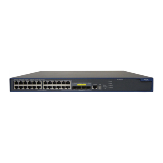
1.2 Panel views 1.2.1 QX-S5526P panel views I. Front panel Figure 1-1 QX-S5526P front panel (1) 10/100/1000BASE-T auto-sensing Ethernet port (2) 10/100/1000BASE-T auto-sensing Ethernet port status LED (3) 100/1000BASE-X SFP Combo port (4) 100/1000BASE-X SFP Combo port status LED... -
Page 11: Qx-S5526P-D Panel Views
(10) Interface module 1 status LED (MOD1) (11) Interface module 2 status LED (MOD2) (12) Port status LED mode switching button II. Rear panel Figure 1-2 QX-S5526P rear panel (1) AC power input (2) RPS power input (3) Grounding screw... -
Page 12: Qx-S5550P Panel Views
(10) Interface module 1 status LED (MOD1) (11) Interface module 2 status LED (MOD2) (12) Port status LED mode switching button II. Rear panel Figure 1-4 QX-S5526P-D rear panel (1) -48V DC power input (2) Grounding screw (3) Interface module slot 1 (MOD1) (4) Interface module slot 2 (MOD2) ... -
Page 13: Qx-S5526T Panel Views
Installation Guide 1 Product overview QX-S5500 Series Ethernet Switches II. Rear panel Figure 1-6 QX-S5550P rear panel (1) AC power input (2) RPS power input (3) Grounding screw (4) Interface module slot 1 (MOD1) (5) Interface module slot 2 (MOD2) ... -
Page 14: Ports
Installation Guide 1 Product overview QX-S5500 Series Ethernet Switches II. Rear panel Figure 1-8 QX-S5526T rear panel (1) Grounding screw (2) Hot swappable power module 1 (3) Hot swappable power module 2 (4) Interface module slot 1 (MOD1) (5) Interface module slot 2 (MOD2) ... -
Page 15: 10/100/1000Base-T Auto-Sensing Ethernet Port
Category-5 twisted pair 100m NOTE: To guarantee the functionality of the SFP+ ports, use only NEC SFP transceiver modules. The SFP transceiver modules available for this switch series are subject to change over time. For the most ... -
Page 16: Combo Port
Ethernet port can be used at a time. For details about the combo port mapping relationship, please refer to Table 1-5. Table 1-5 Combo port mapping relationship Model SFP ports 10/10/1000BASE-T ports GigabitEthernet1/0/25 GigabitEthernet1/0/22 QX-S5526P GigabitEthernet1/0/26 GigabitEthernet1/0/24 QX-S5526P-D GigabitEthernet1/0/27 GigabitEthernet1/0/21 GigabitEthernet1/0/28 GigabitEthernet1/0/23... -
Page 17: Hot Swappable Power Module Status Leds
Installation Guide 1 Product overview QX-S5500 Series Ethernet Switches 1.4.2 Hot Swappable Power Module Status LEDs The hot swappable power module status LEDs help you determine the working status of a hot swappable power module. Only the QX-S5526T supports this type of LEDs. Refer to Table 1-7 for details. -
Page 18: Seven-Segment Led
Installation Guide 1 Product overview QX-S5500 Series Ethernet Switches 1.4.5 Seven-Segment LED The seven-segment LED and the system status LED together indicate the operating status of the device. For details, refer to Table 1-10 Table 1-10 Seven-segment LED description Status Description SYS LED Seven-segment LED... -
Page 19: 100/1000Base-X Sfp Port Status Led
Installation Guide 1 Product overview QX-S5500 Series Ethernet Switches Ethernet port status Port mode LED Description The port is not up. Steady The port operates in full-duplex mode. green The data is being sent and/or received on Flashing the port. Steady yellow Steady The port operates in full-duplex mode. -
Page 20: Optional Interface Modules
A 2-port 10 GE CX4 interface module provides two 10 Gbps electrical ports and supports CX4 electrical and protocol standards. Only NEC's CX4 cables can be used for connecting the CX4 ports. A CX4 cable is hot swappable and its maximum transmission distance is 3 m, which is suitable for short-distance connections only. -
Page 21: 2-Port 10G Base-Xfp Interface Module (Ls-Sp2-T2)
Installation Guide 1 Product overview QX-S5500 Series Ethernet Switches Following CX4 cables supported by the 2-port 10 GE CX4 interface module 10GBASE-CX4 cable A(50cm) [CAB-CX4T2-50CM] 10GBASE-CX4 cable B(100cm) [CAB-CX4T2-100CM] 10GBASE-CX4 cable C(300cm) [CAB-CX4T2-300CM] Figure 1-11 CX4 cable Handle Handle Connector 1... - Page 22 A 2-port 10G BASE-XFP interface module provides two 10 Gbps SFP+ ports. You can insert an SFP+ transceiver into the port to connect it to another SFP+ port through an optical fiber, or an SFP+ cable provided by NEC. For details about the supported SFP+ transceivers and SFP+ cables, refer to Table 1-15.
-
Page 23: 2-Port 10G Base-Xfp Interface Module (Ls-Xp2-T2)
1550 nm optical fiber 40 km NOTE: You must use XFP transceivers of the QX series. The types of XFP transceivers may update with time. For information about transceivers, contact NEC technical support or marketing staff. 1-15... -
Page 24: 1-Port 10G Base-Xfp Interface Module (Ls-Xp1-T2)
Installation Guide 1 Product overview QX-S5500 Series Ethernet Switches 1.5.4 1-port 10G BASE-XFP interface module (LS-XP1-T2) Figure 1-17 1-port 10G BASE-XFP interface module (LS-XP1-T2) Port LED Figure 1-18 1-port 10G BASE-XFP interface module front panel (LS-XP1-T2) Port LED This module provides one 10 Gbps XFP optical interface. You can select the following XFP transceivers as required. - Page 25 Installation Guide 1 Product overview QX-S5500 Series Ethernet Switches Table 1-17 Description of LEDs on interface modules Mark Status Description Steady The port is normally connected. green Port LED of an interface — Flashing module The port is sending or receiving data. green The port is not up.
- Page 26 Installation Guide QX-S5500 Series Ethernet Switches Contents Contents 2 Preparing for installation ......................2-1 2.1 Safety recommendations ....................2-1 2.2 Connecting the RJ45 connector ..................2-1 2.3 Examining the installation site ................... 2-2 2.4 Temperature/humidity ......................2-2 2.5 Cleanness .......................... 2-3 2.6 EMI .............................
-
Page 27: Preparing For Installation
Installation Guide 2 Preparing for installation QX-S5500 Series Ethernet Switches 2 Preparing for installation 2.1 Safety recommendations To avoid any equipment damage or bodily injury caused by improper use, read the following safety recommendations before installation. Note that the recommendations do not cover every possible hazardous condition. -
Page 28: Examining The Installation Site
Installation Guide 2 Preparing for installation QX-S5500 Series Ethernet Switches Figure 2-1 Connecting the RJ45 connector 2.3 Examining the installation site The QX-S5500 Series switches must be used indoors. Mount your switch in a rack or on a workbench and make sure: Adequate clearance is reserved at the air inlet and exhaust vents for ventilation. -
Page 29: Cleanness
Installation Guide 2 Preparing for installation QX-S5500 Series Ethernet Switches 2.5 Cleanness Dust buildup on the chassis may result in electrostatic adsorption, which causes poor contact of metal components and contact points, especially when indoor relative humidity is low. In the worst case, electrostatic adsorption can cause communication failure. Table 2-1 Dust concentration limit in the equipment room Substance Concentration limit (particles/m³) -
Page 30: Installation Tools
Installation Guide 2 Preparing for installation QX-S5500 Series Ethernet Switches WARNING! Do not stare into any fiber port when the switch has power. The laser light emitted from the optical fiber may hurt your eyes. 2.8 Installation tools Flathead screwdriver ... - Page 31 Installation Guide QX-S5500 Series Ethernet Switches Contents Contents 3 Installing the Switch ........................3-1 3.1 Installation of hardware ...................... 3-1 3.1.1 Installing the Switch into a 19-Inch Rack Using Mounting Brackets ....... 3-1 3.1.2 Mounting the Switch on a Workbench..............3-2 3.2 Connecting the Power Cords and the Grounding Cable ...........
-
Page 32: Installing The Switch
Installation Guide 3 Installing the Switch QX-S5500 Series Ethernet Switches 3 Installing the Switch 3.1 Installation of hardware 3.1.1 Installing the Switch into a 19-Inch Rack Using Mounting Brackets An installation procedure is explained below. NOTE: Mounting brackets of this switch standard attachment, the EIA standard, it corresponds to 19-inch standard cabinet based. -
Page 33: Mounting The Switch On A Workbench
Installation Guide 3 Installing the Switch QX-S5500 Series Ethernet Switches I. Mounting method of bracket for fronts Figure 3-2 Mounting method of a front mounting bracket Front mounting bracket screw Front mounting bracket QX-S5500 Series Ethernet Switches has one front mounting position (near the network ports) and one rear mounting position (near the power modules). - Page 34 Installation Guide 3 Installing the Switch QX-S5500 Series Ethernet Switches Figure 3-3 Power socket (recommended) Neutral point Neutral point Live line Live line Zero line Zero line II. Connecting the AC Power Cable Connect one end of the grounding cable to the grounding screw on the rear of the chassis and the other end to the ground as near as possible.
-
Page 35: Connecting The -48V Dc Power Cord
CAUTION: Before connecting to DC power cord, disconnect the switch and a power supply. QX-S5526P-D and PSR150-D1 of the QX-S5526T have a –48 VDC power receptacle, allowing the use of the –48 VDC power supply in the equipment room. Follow these steps to connect a –48V DC power cord to the switch: Please install an appropriate ring terminal which matches the outside power supply in the DC power supply side terminal for power cord. -
Page 36: Grounding The Grounding Cable
Installation Guide 3 Installing the Switch QX-S5500 Series Ethernet Switches Figure 3-5 Connecting point of DC power cord (1) Power cable fixed screw (2) The power supply handle (3) Power module fixed screw (4) G : -48V Earth (5) -48 : -48 (6) NULL : Reserved 3.2.3 Grounding the Grounding Cable WARNING:... -
Page 37: Connection Procedure
Installation Guide 3 Installing the Switch QX-S5500 Series Ethernet Switches Figure 3-6 Console cable A side Pos.9 Main label B side Pos.1 RJ-45 Direction DB-9 Signal CTS(CS) DSR(DR) RXD(RD) GND(SG) - GND(SG) - TXD(SD) DTR(ER) RTS(RS) ... -
Page 38: Checklist After Installation
Installation Guide 3 Installing the Switch QX-S5500 Series Ethernet Switches 3.4 Checklist after installation After installation has been completed, please confirm the following thing. The used power supply matches label indication of the switch. The grounding cable is connected. ... - Page 39 Installation Guide QX-S5500 Series Ethernet Switches Contents Contents 4 Starting and Configuring the Switch ..................4-1 4.1 Setting up the Configuration Environment ................. 4-1 4.2 Connecting the Console Cable ..................4-1 4.3 Setting Terminal Parameters ..................... 4-1 4.4 Booting the Switch ......................4-5 4.4.1 Checking before Power-On ..................
-
Page 40: Starting And Configuring The Switch
Installation Guide 4 Starting and Configuring the Switch QX-S5500 Series Ethernet Switches 4 Starting and Configuring the Switch 4.1 Setting up the Configuration Environment Set up the configuration environment as follows: Connect a terminal (a PC in this example) to the console port on the switch with a console cable. - Page 41 Installation Guide 4 Starting and Configuring the Switch QX-S5500 Series Ethernet Switches On Windows 7, Windows Vista, or another operating system, obtain a third-party terminal control program first, and then follow the user guide or online help to log in to the device.
- Page 42 Installation Guide 4 Starting and Configuring the Switch QX-S5500 Series Ethernet Switches Figure 4-3 Set the serial port used by the HyperTerminal connection Click OK after selecting a serial port and the following interface pops up. On the interface, set Bits per second to 9600, Data bits to 8, Parity to None, Stop bits to 1, and Flow control to None.
- Page 43 Installation Guide 4 Starting and Configuring the Switch QX-S5500 Series Ethernet Switches Click OK after setting the serial port parameters and the system enters the following interface. Figure 4-5 HyperTerminal window Click Properties in the HyperTerminal window to enter the properties window. Click Settings to enter the following properties setting window, set the emulation to VT100, and then click OK.
-
Page 44: Booting The Switch
The QX-S5500 series have the same Boot ROM display style. This document uses the Boot ROM display of QX-S5526P as an example: NOTE: The indication message indicated below is different depending on the models and the versions a little. - Page 45 Installation Guide 4 Starting and Configuring the Switch QX-S5500 Series Ethernet Switches The last line asks whether you want to enter the Boot Menu. The system waits two seconds for your response. If you press <Ctrl + B> within two seconds, the Boot Menu is displayed: ...
-
Page 46: Changing The Boot Mode
Installation Guide 4 Starting and Configuring the Switch QX-S5500 Series Ethernet Switches Enter your choice(0-9): Software of Version 5.4.8 or previous version: BOOT MENU 1. Download application file to flash 2. Select application file to boot 3. Display all files in flash 4. - Page 47 Installation Guide 4 Starting and Configuring the Switch QX-S5500 Series Ethernet Switches BOOT MENU 1. Download application file to flash 2. Select application file to boot 3. Display all files in flash 4. Delete file from flash 5. Modify bootrom password 6.
- Page 48 4 Starting and Configuring the Switch QX-S5500 Series Ethernet Switches NEC QX-S5526P BOOTROM, Version 720 *********************************************************** Copyright (c) 2004-2013 NEC Corporation. All rights reserved. Creation date : Sep 25 2013, 23:19:08 CPU Clock Speed : 533MHz BUS Clock Speed : 133MHz...
- Page 49 Installation Guide 4 Starting and Configuring the Switch QX-S5500 Series Ethernet Switches Decompress Image........................................................................................................OK! Starting at 0x80100000... Initialize LS55LTSF......OK! SDRAM fast selftest......OK! Flash fast selftest......OK! CPLD selftest......OK! Switch chip selftest.......OK! Port 1 has no module Port 2 has no module Port 3 has no module Port 4 has no module...
- Page 50 Installation Guide QX-S5500 Series Ethernet Switches Contents Contents 5 Network connection of the switch .................... 5-1 5.1 Network connection by a twisted pair cable............... 5-1 5.1.1 Twisted pair cable ....................5-1 5.1.2 Connection by a twisted pair cable ................. 5-4 5.2 Network connection by a fiber-optic cable .................
-
Page 51: Network Connection Of The Switch
Installation Guide 5 Network connection of the switch QX-S5500 Series Ethernet Switches 5 Network connection of the switch NOTE: Before connecting a network, it's recommended to set it as the switch basically. ping or the tracert command can be used to make sure of the interoperability of the switch and the network ... - Page 52 Installation Guide 5 Network connection of the switch QX-S5500 Series Ethernet Switches Pin 1: white, orange, pin 2: orange, pin 3: white, green, pin 4: blue, pin 5: white, blue, pin 6: green, pin 7: white, brown and pin 8: brown III.
- Page 53 Installation Guide 5 Network connection of the switch QX-S5500 Series Ethernet Switches Figure 5-3 Crossing cable white/orange orange white/green blue white/blue green white/brown brown Crossover cable white/green green white/orange blue white/blue orange white/brown brown IV. Pin arrangement RJ-45 Ethernet interface is one of MDI (for routers and PCs) or MDI-X (for switches). Refer to Table 5-2 and Table 5-3 about pin-out of RJ-45 Ethernet interface.
-
Page 54: Connection By A Twisted Pair Cable
Installation Guide 5 Network connection of the switch QX-S5500 Series Ethernet Switches 10Base-T/100Base-TX 1000Base-T Signal Function Signal Function Reserve BIDC+ Line of bi-directional data C+ Reserve BIDC- Line of bi-directional data C- To establish normal communication, pin for transmission data has to make them match with pin for receive data in an opposite port. -
Page 55: Establishment Of A Sfp Module
Installation Guide 5 Network connection of the switch QX-S5500 Series Ethernet Switches 5.2.1 Establishment of a SFP module NOTE: This section describes establishment of a SFP module and an operational guideline. I. Installation procedure of a SFP module Wear an ESD-preventive wrist strap and make sure it makes good skin contact and is well grounded. - Page 56 Installation Guide 5 Network connection of the switch QX-S5500 Series Ethernet Switches in the switch. Connect the plug by which a connector is already the other to a module of opposite equipment. Confirm that an LED of optical interface is normal. When an LED doesn't light up, confirm whether the location where a fiber connector is connected (RX/TX) is right.
- Page 57 Installation Guide QX-S5500 Series Ethernet Switches Contents Contents 6 Upgrading Software/Boot ROM ....................6-1 6.1 Upgrade method ........................ 6-1 6.2 Upgrade of software by local ..................... 6-1 6.2.1 Boot menu ....................... 6-1 6.2.2 Upgrade of software by TFTP ................. 6-3 6.2.3 Upgrade of software by FTP ...................
-
Page 58: Upgrading Software/Boot Rom
Before loading the software, make sure that your terminal is correctly connected to the switch. 6.2.1 Boot menu It's indicated taking the QX-S5526P switch for instance. After turning on the power of the switch, a Boot Rom program is executed first. The following information is shown to a terminal display. - Page 59 Installation Guide 6 Upgrading Software QX-S5500 Series Ethernet Switches *********************************************************** NEC QX-S5526P BOOTROM, Version 509 *********************************************************** Copyright (c) 2004-2009 NEC Corporation. All rights reserved. Creation date : Jan 9 2009, 10:44:09 CPU Clock Speed : 533MHz BUS Clock Speed : 133MHz...
-
Page 60: Upgrade Of Software By Tftp
Installation Guide 6 Upgrading Software QX-S5500 Series Ethernet Switches 3. Display all files in flash 4. Delete file from flash 5. Modify bootrom password 6. Enter bootrom upgrade menu 7. Skip current configuration file 8. Set bootrom password recovery 9. Set switch startup mode 0. -
Page 61: Upgrade Of Software By Ftp
Installation Guide 6 Upgrading Software QX-S5500 Series Ethernet Switches Writing to flash..........done Enter "0" in the download program menu to restart the device. After that, the updated Boot ROM file becomes effective. NOTE: When making switch restart from the Boot menu, please choose "0" by the Boot menu. 6.2.3 Upgrade of software by FTP Choose Ethernet interface of QX-S5500 series switch for download. -
Page 62: Upgrade Of Software By Xmodem
Installation Guide 6 Upgrading Software QX-S5500 Series Ethernet Switches 6.2.4 Upgrade of software by Xmodem NOTE: When upgrading software by an Xmodem protocol, use a terminal emulation program which corresponds to an Xmodem protocol. A circuit band is small and Xmodem needs much time in software download work. It's explained about an operational example of Hyper Terminal in Windows XP by this document. - Page 63 Installation Guide 6 Upgrading Software QX-S5500 Series Ethernet Switches Figure 6-1 Send file dialog box Click Send. The following dialog box appears: Figure 6-2 Page for file sending After the program file is downloaded, the terminal displays the following information: Loading ...CCCCCCCCCC done! ## Total Size = 0x00055d40 = 351552 Bytes...
-
Page 64: Upgrade Of Software By Remote
Installation Guide 6 Upgrading Software QX-S5500 Series Ethernet Switches 6.3 Upgrade of software by remote When a terminal is connected to the switch by a network, software can be upgraded remotely. 6.3.1 Upgrade of software by FTP Carry out the FTP server as which the user name, a password and a file directory are set right on the local end. -
Page 65: Upgrade Of Boot Rom By Local
Before loading the Boot ROM, make sure that your terminal is correctly connected to the switch. 6.4.1 Boot menu It's indicated taking the QX-S5526P switch for instance. After turning on the power of the switch, a Boot Rom program is executed first. The following information is shown to a terminal display. - Page 66 Installation Guide 6 Upgrading Software QX-S5500 Series Ethernet Switches NOTE: To enter the Boot Menu, you must press <Ctrl+B> within two seconds after the information “Press Ctrl-B to enter Boot Menu...” appears. Otherwise, the system starts to decompress the program; and if you want to enter the Boot Menu at this time, you will have to restart the switch.
-
Page 67: Upgrade Of Boot Rom By Tftp
Installation Guide 6 Upgrading Software QX-S5500 Series Ethernet Switches 6.4.2 Upgrade of Boot ROM by TFTP Choose Ethernet interface of QX-S5500 series switch for download. Connect QX-S5500 series switch to the terminal where a downloaded file through an interface is put. (We assume that the IP address of a terminal is known.) At the same time, Connect QX-S5500 series switch to the terminal where a downloaded file through a console port is put. -
Page 68: Upgrade Of Boot Rom Software By Xmodem
Installation Guide 6 Upgrading Software QX-S5500 Series Ethernet Switches Connect QX-S5500 series switch to the terminal where a downloaded file through a console port is put. Execute a FTP server program on the terminal connected to QX-S5500 series switch through Ethernet interface for download. Specify a file pass of an upgrade program. Run the terminal emulation program on the PC connected with the switch’s console port. - Page 69 Installation Guide 6 Upgrading Software QX-S5500 Series Ethernet Switches 5. 115200 0. Return Enter your choice (0-5):5 Select an appropriate download baud rate. For example, if you select "5", the 115200 bps rate is chosen, and the system displays the following information: Download baudrate is 115200 bps.Please change the terminal's baudrate to 115200 bps, and select XMODEM protocol.
-
Page 70: Upgrade Of Boot Rom Software By Remote
Installation Guide 6 Upgrading Software QX-S5500 Series Ethernet Switches Figure 6-4 Page for file sending After the program file is downloaded, the terminal displays the following information: Loading ...CCCCCCCCCC done! ## Total Size = 0x00055d40 = 351552 Bytes Your baudrate should be set to 9600 bps again! Press enter key when ready. -
Page 71: Upgrade Of Software By Tftp
Installation Guide 6 Upgrading Software QX-S5500 Series Ethernet Switches 331 Give me your password, please Password: 230 Logged in successfully [ftp] get SWITCH.app [ftp] bye Specify the Boot ROM software used at next-startup. <QX> bootrom update file SWITCH.app slot 1 <QX>... -
Page 72: Upgrade Of Software By Tftp
Installation Guide 6 Upgrading Software QX-S5500 Series Ethernet Switches User(none):lyt 331 Give me your password, please Password: 230 Logged in successfully [ftp] get SWITCH.app [ftp] bye <QX>copy SWITCH.app slot2#flash:/ Specify the software for all member switches used at next-startup. <QX> boot-loader file SWITCH.app slot 1 main <QX>... -
Page 73: Upgrade Of Boot Rom Software By Tftp
Installation Guide 6 Upgrading Software QX-S5500 Series Ethernet Switches The Boot ROM software program is made SWITCH.app. After logging on to the switch using Telnet, follow the next procedure. Download the Boot ROM software to the switch using FTP. After downloading it in Master, copy a file in all member switches using the copy command. - Page 74 Installation Guide QX-S5500 Series Ethernet Switches Contents Contents 7 Maintenance and Troubleshooting ................... 7-1 7.1 Exchange of a power supply module ................. 7-1 7.2 Software Loading Failure ....................7-2 7.3 Password recovery ......................7-2 7.3.1 Password recovery of user password ..............7-2 7.3.2 Recovery of Boot ROM password.
-
Page 75: Maintenance And Troubleshooting
Installation Guide 7 Maintenance and Troubleshooting QX-S5500 Series Ethernet Switches 7 Maintenance and Troubleshooting 7.1 Exchange of a power supply module CAUTION: QX-S5526T has power supply module of the AC type and DC-type. You can select AC power module or DC power module for your switch as needed. -
Page 76: Software Loading Failure
Installation Guide 7 Maintenance and Troubleshooting QX-S5500 Series Ethernet Switches 7.2 Software Loading Failure When a software load was failed, system must start up by original software, or perform an update locally from the Boot menu. Check the following and download software once again. A physical port is connected right. -
Page 77: Recovery Of Boot Rom Password
Installation Guide 7 Maintenance and Troubleshooting QX-S5500 Series Ethernet Switches 4. Delete file from flash 5. Modify bootrom password 6. Enter bootrom upgrade menu 7. Skip current configuration file 8. Set bootrom password recovery 9. Set switch startup mode 0. Reboot Enter your choice(0-9): Step2: Select "7"... -
Page 78: Way Of Load Failure Of The Next-Startup Configuration File
Installation Guide 7 Maintenance and Troubleshooting QX-S5500 Series Ethernet Switches 7.3.3 Way of load failure of the next-startup configuration file Perform the following task, when failing in a load of the next startup configuration file. Please confirm whether the next startup configuration file is set. Step1: Execute dir commands in user view to verify the next-startup configuration file at Flash. - Page 79 Installation Guide 7 Maintenance and Troubleshooting QX-S5500 Series Ethernet Switches 8. Set bootrom password recovery 9. Set switch startup mode 0. Reboot Enter your choice(0-9): Select "7" in the Boot Menu, and then press <Enter> When indicating “The current setting is skipping configuration file when reboot.”, startup configuration file is default.
-
Page 80: Power Supply Failure
Installation Guide 7 Maintenance and Troubleshooting QX-S5500 Series Ethernet Switches 7.4 Power Supply Failure You can check whether the power system of the switch fails by viewing the PWR LED on the front panel. When the power supply system functions normally, the PWR LED should be ON.