
Related Manuals for NEC MM2000


Summary of Contents for NEC MM2000
- Page 1 ® Multimedia Switcher for DLP Cinema Projector MM2000 User’s Manual NEC Viewtechnology, Ltd.
-
Page 2: Important Information
Switcher and keep the manual handy for future reference. product may cause radio interference in which case the user Your serial number is located on the top of your MM2000 may be required to take adequate measures. Switcher. Record it here: CAUTION •... - Page 3 In Europe become heated while the switcher is turned on. NEC Europe, Ltd. / European Technical Centre • Do not eject a PC card or LAN card while its data is being Address: Unit G, Stafford Park 12, Telford TF3 3BJ, U.K.
-
Page 4: Informations Importantes
Veuillez lire ce manuel avec attention avant d’utiliser votre • Windows est une marque commerciale ou une marque commutateur MM2000 et gardez ce manuel à portée de main commerciale déposée de Microsoft Corporation aux Etats-Unis afin de pouvoir y recourir facilement. - Page 5 10 cm d’espace entre le commutateur et le mur. En Europe • Evitez de faire tomber dans le commutateur des objets NEC Europe, Ltd. / European Technical Centre étrangers comme des trombones ou des morceaux de Adresse : Unit G, Stafford Park 12, Telford TF3 3BJ, U.K.
- Page 6 Der höchste Schalldruckpegel beträgt 70 dB(A) oder weniger gemäß EN ISO 7779. Lesen Sie sich dieses Handbuch bitte sorgfältig durch, bevor Sie den MM2000 Switcher benutzen, und bewahren Sie das Wechselstrom-Netzkabel für Großbritannien Handbuch in greifbarer Nähe als spätere Referenz auf.
- Page 7 • Lassen Sie die PC-Karte oder LAN-Karte nicht auswerfen, In Europa während auf ihre Daten zugegriffen wird. Dies kann zu NEC Europe, Ltd. / European Technical Centre einer Beschädigung der PC-Karte oder LAN-Karte führen. Addresse: Unit G, Stafford Park 12, Telford TF3 3BJ, U.K.
- Page 8 Important Information (MEMO)
-
Page 9: Table Of Contents
Table of Contents 1.Introduction ................. 2 1-1. Features ..................................2 1-2. What’s in the Box? ..............................3 1-3. Getting to Know Your Switcher ..........................4 2.Installation ................. 10 2-1. Making Connections .............................. 10 2-2. Connecting Your Projector ............................ 11 2-3. Connecting to the Image Input Terminals ......................12 2-4. -
Page 10: Introduction
Introduction 1-1. Features • 3D Motion Adaptive I/P Conversion Supports a Multi-directional Filter for HDTV Differing from the conventional 3D Motion Adaptive interpolation method, this provides optimum interpolation even in oblique directions of the moving image. Therefore, image quality performance of image contents are drawn out to the maximum limit when converting to progressive signals. -
Page 11: What's In The Box
1. Introduction 1-2. What’s in the Box? The accessory contents are as follows: • Multimedia Switcher (MM2000) • Ferrite clamp core • Power cable x3 • Power cable for Japan (for Power cable / RGB cables) x2 AC100V • Band x2 •... -
Page 12: Getting To Know Your Switcher
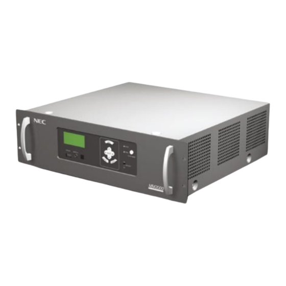
1. Introduction 1-3. Getting to Know Your Switcher 1-3-1. Front of the Switcher Control panel (See page 5) Ventilation (inlet) Handles 1-3-2. Rear of the Switcher Main power switch (See page 16) AC INPUT (See page 15) Ventilation (outlet) Image input terminals Control terminals / (See page 7) Image output terminals... -
Page 13: Control Panel
1. Introduction 1-3-3. Control Panel 1. LCD Screen 7. POWER Indicator The liquid crystal display screen shows the condition or When this indicator is green, the Switcher is on; when this the error message of the Switcher. indicator is orange, it is in standby mode. 2. - Page 14 1. Introduction 1-3-4. Control Terminals/Image Output Terminals 1. LAN port (RJ-45) This port is used for linked control from the NC series projector or for control of this unit from a PC. Use a commercially available LAN cross cable 10Base-T/100Base-T) for connection. 2.
- Page 15 1. Introduction 1-3-5. Image Input terminals You can mount various interface boards to any position you want among slots 1 to 4. For removal and installation of the interface board, see page 13. 1.SLOT 1 (MM-VIDEO) 2. SLOT 2 (MM-RGB) MM-VIDEO interface board is standard equipment.
-
Page 16: Option Boards
1. Introduction 1-3-6. Option Boards MM-SDI Interface Board (Option) The SDI signal input board is available as an option. (1) STATUS Indicator Steady green light ..Shows that a signal is present. Steady red light ... Shows that there is no signal or an error occurs. Steady orange light .. - Page 17 1. Introduction MM-DVI Interface Board (Option) The DVI signal input board is available as an option. (1) DVI-D Input Connector (DVI-D 24 Pin) Use a DVI-D Signal cable and connect it to the DVI output connector of a computer. (2) ACT Indicator Steady green light ..
-
Page 18: Installation
Installation 2-1. Making Connections When using with a notebook PC, be sure to connect between the Switcher and the notebook PC before turning NOTE on the power to the notebook PC. In most cases signal cannot be output from RGB output unless the notebook PC is turned on after connecting with the Switcher. -
Page 19: Connecting Your Projector
DVI-D signal cables. Alternatively, when a mode to control this unit from the projector (linked mode) is used, connect this unit with the projector using a LAN cable. DVI OUT-B DVI OUT-A MM2000 DVI-D signal cable (not supplied) NC series projector DVI-A... -
Page 20: Connecting To The Image Input Terminals
This Switcher has two interface boards, MM-VIDEO and MM-RGB as standard equipment. See page 7. Connect required video signals. Four interface boards can be inserted in the Switcher at the same time. See page 13. COMPONENT MM2000 RCA(female)-to-BNC(male) adapter (not supplied) -
Page 21: Install The Option Boards And Expand The Image Input Terminals
2. Installation 2-4. Install the Option Boards and Expand the Image Input Terminals Four types of option boards are available for the Switcher. Please purchase as required. Warning When installing or removing the board from the Switcher, do so after turning off the main power switch of the Switcher. -
Page 22: Connecting To A Network
Contact your dealer/distributor about use of the switcher in standalone mode. [Example of Connection with LAN] Touch panel controller (option) NC series projector Server LAN cable* (not supplied) MM2000 * When the switcher and PC are connected, use the LAN cross cable. -
Page 23: Connecting The Supplied Power Cable
2. Installation 2-6. Connecting the Supplied Power Cable Connect the supplied power cable to the Switcher. First connect the supplied power cable’s three-pin plug to the AC IN of the Switcher, and then connect the other plug of the supplied power cable in the wall outlet. M a k e s u r e t h a t t h e prongs are fully inserted into both the AC IN and... -
Page 24: Projecting An Image
Projecting an Image Specify “Title select” from the projector to project images of a device connected to this unit. Refer to the Projector User’s Manual for details on how to operate the projector. The procedures to turn on and off this unit are described below. 3-1. -
Page 25: Turning Off The Switcher
3. Projecting an Image 3-2. Turning off the Switcher To turn off the Switcher: First press the POWER (ON/STAND BY) button on the Switcher cabinet for a minimum of 1 second. The POWER indicator will glow orange. Power on Standby POWER POWER ON/STAND BY... -
Page 26: Lcd Menu
LCD Menu 4-1. Basic operation from LCD screen menu With the LCD screen menu, you can display various information about this unit. 4-1-1. Screen display When not displaying the menu, the following screen is usually displayed. When in standby When this unit is in the standby state, the following is displayed. When power is on When the power is turned on, the following is displayed. -
Page 27: List Of Lcd Screen Menus
4. LCD Menu 4-1-2. Operating menus Preparation: Turn on the unit (See page 16). Press the MENU button. A menu is displayed on the LCD screen. Press the SELECT button to display “Version”. button, the display changes among “Version” ←→ “IP Address” ←→ “Error Code”. As you press the SELECT Press the SELECT button. -
Page 28: Maintenance
Maintenance 5-1. Cleaning the Cabinet Turn off the Switcher before cleaning. Clean the cabinet periodically with a damp cloth. If heavily soiled, use a mild detergent. Never use strong detergents or solvents such as alcohol or thinner. -
Page 29: Appendix
Appendix 6-1. Troubleshooting Before asking for repair, please check your connection, settings and operation once again. For control of the switcher, contact the person in charge of setting and adjustment. If the trouble cannot be corrected, please contact your dealer/distributor for instructions or repair. -
Page 30: Error Code List
LCD screen). This sometimes sets the external output signal to a signal that is standard. 6-2. Error code list Error messages relating to MM2000 are displayed in the LCD screen of the switcher, the LCD screen of the projector, and the touch panel (optional). -
Page 31: Compatible Input Signal List
6. Appendix 6-3. Compatible input signal list Frequency Signal Board type Resolution Horizontal freq. [kHz] Refresh rate. [Hz] Dots [MHz] NTSC VIDEO 15.73 59.94 i VIDEO 15.63 50 i PAL60 VIDEO 15.73 59.94 i SECAM VIDEO 15.63 50 i VESA RGB / DVI 640 x 480 31.47... -
Page 32: Specifications
6. Appendix 6-4. Specifications Model Number MM2000 BNC x 1, 75 Ω, 1.0 Vp-p Image Input VIDEO Composite Video BNC x 2, 75 Ω, Y: 1.0 Vp-p C: 0.28 to 0.3 Vp-p S-Video BNC x 3, 75 Ω, Y: 1.0 Vp-p Cb, Cr: ±0.35 Vp-p... - Page 33 6. Appendix PC Card Type II x 1 (For service personnel) Function Image switching Quick seamless switching (function expansion) 2 screen mode Picture-in-picture, side-by-side (function expansion) Keystone correction Vertical correction (function expansion) Projector connection Linking function through PC control Environment Operational Temperature 5 to 35˚C Operational Humidity...
-
Page 34: Caracteristiques Techniques
6. Appendix Caracteristiques techniques Numéro de modèle MM2000 Entrée d'image VIDEO Vidéo Composite BNC x 1, 75 ohms, 1,0 Vp-p S-Vidéo BNC x 2, 75 ohms, Y: 1,0 Vp-p C: 0,28 à 0,3 Vp-p BNC x 3, 75 ohms, Y: 1,0 Vp-p Cb, Cr: ±0,35 Vp-p Vidéo Composante... - Page 35 6. Appendix Carte PC Type II x 1 (Pour le personnel de service) Fonction Commutation d'image Commutation continue rapide (extension de fonction) 2 modes d'écran Image par image, côte à côte (extension de fonction) Correction trapézoïdale Correction verticale (extension de fonction) Connexion du projecteur Fonction de lien par contrôle PC Environnement...
-
Page 36: Technische Daten
6. Appendix Technische Daten Modellnummer MM2000 Bildeingang VIDEO Komposit-Video BNC x 1, 75 Ohm, 1,0 Vp-p S-Video BNC x 2, 75 Ohm, Y: 1,0 Vp-p C: 0,28 bis 0,3 Vp-p BNC x 3, 75 Ohm, Y: 1,0 Vp-p Cb, Cr: ±0,35 Vp-p Komponentenvideo Horizontale Auflösung... - Page 37 6. Appendix PC-Karte Typ II x 1 (Für servicepersonal) Funktion Bildumschaltung Schnelle nahtlose Umschaltung (Funktionserweiterung) 2-facher Bildschirm-Modus Bild-in-Bild, Bilder nebeneinander (Funktionserweiterung) Trapezkorrektur Vertikale Korrektur (Funktionserweiterung) Projektor-Anschluss Verbindungsfunktion durch die PC-Steuerung Umgebung Betriebstemperatur 5 bis 35˚C Luftfeuchtigkeit 10 bis 85% (Kondensation darf nicht vorhanden sein) Lagerungsumgebung Lagertemperatur -10 bis 50˚C...
-
Page 38: Cabinet Dimensions
6. Appendix 6-5. Cabinet Dimensions Units = mm... - Page 39 © NEC Viewtechnology, Ltd. 2006 Printed in Japan Ver.1 08/06...
- Page 40 Printed on recycled paper 7N8P6981...