Table of Contents
Advertisement
SERVICE AND INSTALLATION
WITH REPLACEMENT PARTS LIST
LC6000-200 CONTROLLER
Part of the Bard Cooling System
NOTE: LC6000-200 controller is required for operation when
multiple MULTI-TEC
MEGA-TEC
Additional information regarding the installation and setup
of the LC6000-200 controller and software is included in
the system installation instructions located inside the wall-
mount unit control panel.
INSTRUCTIONS
, FUSION-TEC
®
wall-mount units are used.
TM
Bard Manufacturing Company, Inc.
Bryan, Ohio 43506
www.bardhvac.com
WR Series and/or
®
Manual :
2100-669F
Supersedes:
2100-669E
Date:
3-18-19
Page
1 of 37
Advertisement
Table of Contents

Related Manuals for Bard LC6000-200


Summary of Contents for Bard LC6000-200
- Page 1 ® MEGA-TEC wall-mount units are used. Additional information regarding the installation and setup of the LC6000-200 controller and software is included in the system installation instructions located inside the wall- mount unit control panel. Bard Manufacturing Company, Inc. Manual :...
-
Page 2: Table Of Contents
Troubleshooting ..........30 Table 6 LC6000-200 Terminal Block Index ..34 8403-079 Remote Indoor Temp/Humidity Sensor ..30 Table 7 LC6000-200 to Sensor Connection Index .. 35 8301-090 Outdoor Temp/Humidity Sensor ....33 LC6000 Replacement Parts List ......37 Manual 2100-669F Page 2 of 37... - Page 3 (one sensor per zone) will need to be purchased and installed in the additional zones. One additional temperature-only sensor (Bard P/N 8301-058) may also be used in Zone 1 but will also need to be purchased separately. Additional temperature/humidity sensors require field-supplied 5-wire 18 gauge shielded cable.
- Page 4 Current software Atlanta, GA 30329-2305 versions, change log and installation Telephone: (404) 636-8400 Fax: (404) 321-5478 instructions are available on the Bard website at http://www.bardhvac.com/software-download/ National Fire Protection Association (NFPA) Batterymarch Park P. O. Box 9101...
-
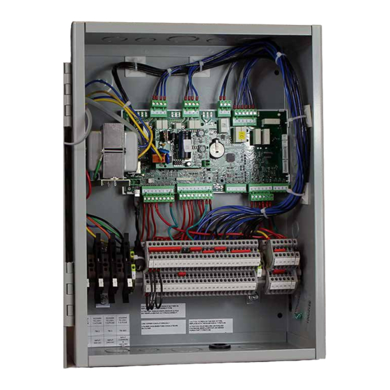
Page 5: Lc6000 Controller Installation
LC6000 CONTROLLER INSTALLATION FIGURE 1 Typical LC6000-200 Component Location RJ11 Cable to Display Transformer Control Board Ethernet Cable Connection USB Male A to Micro Male Four Fused B Cable Power Supply Terminals Emergency Off Alarm Jumper Emergency Vent Alarm Jumper... -
Page 6: Lc6000 Controller
IMPORTANT: When working with circuit board connecting wires to the terminal block, confirm that the components, Bard recommends the use of fuse in each of the four fuse holders is in the proper an anti-static wrist strap to prevent static position (active) as shown in Figure 2. -
Page 7: Supply Wiring
Supply Wiring The LC6000 controller is powered by 120, 208 or 240 volts from the shelter. Field-supplied supply wiring should be minimum 16 gauge, maximum 14 gauge (see Figure 3). A reliable earth ground must be connected in addition to any grounding from conduit. Grounding bolts and nuts are included with the controller for this purpose; a 2 hole grounding lug must be field supplied. -
Page 8: Installing Remote Indoor Temperature/Humidity Sensor(S)
Installing Remote Indoor Temperature/Humidity Sensor(s) One remote indoor temperature/humidity sensor and 35' of 18 gauge 5-conductor shielded cable is included with the controller. This sensor must be installed for proper operation. Mount the temperature/humidity sensor in a location least likely to be affected by open doors, rack-mounted fans, radiant heat sources, etc. Locating the sensor between both return grilles is often the best location, but every installation is unique. -
Page 9: Figure 1 Figure
For proper operation, the remote indoor temperature/humidity sensor (and any additional sensors) must be configured properly with the controller as shown in Step 2 on page 8. An additional remote indoor temperature- only sensor can be purchased and installed in Zone 1. If the site in which the LC6000 controller will be used has more than one zone (maximum three zones per LC6000), additional remote temperature/humidity sensors (one per zone) will need to be purchased and installed in the additional zones. -
Page 10: Figure 3 Figure
Installing Optional Outdoor Temperature/Humidity Sensor One optional outdoor temperature/humidity sensor (8301-090) can be installed. Follow the manufacturer's mounting instructions. Use 18 gauge 5-conductor shielded cable to connect to controller. FIGURE 7 Remote Outdoor Temperature/Humidity Sensor Installation Connect wires from the 18 gauge shielded cable to terminals #65, #66, #67, #70 and #71. Wire Sensor Description... -
Page 11: Run Connections
Emergency Off, Emergency Ventilation and Generator Run Connections The LC6000-200 controller is shipped with emergency off, emergency ventilation and generator run contacts. There are factory-installed jumpers across terminals #6 and #7 (emergency off), #8 and #9 (emergency ventilation) and #10 and #11 (generator run). Remove the factory-installed jumpers before making the connections. -
Page 12: Communication Wiring
Communication Wiring The steps outlined on the following pages show how to connect the communication wiring to the LC controller. Communication wire connections to the wall-mount unit vary with the different units. See the system installation instructions included with the wall-mount unit for information on connecting the communication wiring to the wall- mount unit(s). -
Page 13: Communication Wiring (Daisy Chain)
The wall-mount units may not look the same as those depicted in the figures but these directions apply to all units connected to the LC6000-200 controller. FIGURE 10 Communication Wiring (Daisy Chain Method) -
Page 14: Figure 6 Figure
FIGURE 12 Placement of Communication Wire Filters (Daisy Chain and Alternate Methods) Daisy Chain Wiring Place filter here Place filter here (end unit) LC6000 Unit 1 Unit 2 Unit 3 Unit 4 Unit 5 ... up to 14 units Alternate Wiring Place filter here Place filter here (end unit) -
Page 15: Alarms
ALARMS NOTE: Screenshots shown in this manual reflect To change the direction of the remote notification relay default settings (when applicable). output: 1. Press MENU key to go to the Main Menu screen. Alarm Adjustment 2. Use UP or DOWN keys and ENTER key to enter Acknowledging/Clearing Alarms USER password 2000. -
Page 16: High Temperature 2 Alarm
2. Use UP or DOWN keys and ENTER key to enter When the Val (value) is OFF, the relay is not in an USER password 2000. alarm condition. When the Val (value) is ON, the relay is in an alarm condition. The relay connections for the 3. -
Page 17: Generator Alarm
To change the direction of the remote notification relay 3. Press UP or DOWN keys to scroll to IO Config; output: press ENTER key. 1. Press MENU key to go to the Main Menu screen. 4. Press UP or DOWN keys to scroll to Digital In Config C1. -
Page 18: Emergency Vent Alarm
6. Press UP or DOWN key to change Disable to To change the direction of the emergency vent input: Enable. 1. Press MENU key to go to the Main Menu screen. 7. Press ENTER key to save the value and move 2. -
Page 19: Humidity Alarm
FIGURE 18 LC to provide remote notification of the event for each zone. Adjust Zone Alarm Configuration To change the direction of the remote notification relay output: 1. Press MENU key to go to the Main Menu screen. 2. Use UP or DOWN keys and ENTER key to enter USER password 2000. -
Page 20: Adjust Humidity Alarm Setpoints
6. Press ENTER key to scroll to Low Humidity, High Humidity or Alarm Delay (delay in seconds from the time the alarm is sensed until the alarm is displayed). See Figure 19. 7. Press UP and DOWN keys to adjust setpoints or delay. -
Page 21: Control Operation
CONTROL OPERATION NOTE: Screenshots shown in this manual reflect FIGURE 20 Change Indoor Temperature Averaging Type default settings (when applicable). Temperature Control Indoor Temperature Averaging The LC has the ability to average all of the zone temperature sensors connected to the LC and the return air temperature sensors connected to the wall- mount unit, use only the zone temperature sensors, or use the LC sensors and any unit which has its blower... -
Page 22: Staging Delay
return air temperature will be brought on first and the Maximum Number of Units Running unit with the highest return temperature will be turned The maximum number of units that will be staged off first. on can be configured for each zone. The number is To change the staging method type: defaulted at the total number of units capable so that they are fully utilized by default. -
Page 23: Demand
6. Press ENTER key to scroll to Time Based (see Humidity Control Figure 23). The changeover time is 12 am. The LC can be configured to control up to three 7. Press UP or DOWN key to change ON to OFF. humidifiers (field supplied) with relay outputs and up to 14 units equipped with dehumidification. -
Page 24: Humidification
Humidification 6. Press ENTER key to scroll to Dehumidification Off, Passive On or Active On (see Figure 24). If the humidity level is below 45% RH (Humidification Setpoint), the LC will enable humidification for 7. Press UP and DOWN keys to change that zone. -
Page 25: Continuous Blower
Continuous Blower 4. Press UP or DOWN keys to scroll to Cont. Blower Cust. B10, Cont. Blower Cust. B11 or Cont. Blower The LC will has the option in each zone to operate in Cust. B12. The wall-mount units are divided continous blower. -
Page 26: Additional Information
ADDITIONAL INFORMATION LC6000 Menus/Screens needed when referencing technical documentation online or contacting Bard Technical Services. Main Menu Press the MENU key from any screen to return to the FIGURE 29 Main Menu. Press the UP or DOWN keys to scroll MULTI-TEC Unit Information Screen through the available menus. -
Page 27: Additional Programming
Additional Programming Menu Screens and Password Levels System Config Changing to Celsius General: User (2000) 1. Press MENU key to go to the Main Menu screen. Zone 1: User (2000) 2. Use UP or DOWN keys and ENTER key to enter Zone 2: User (2000) USER password 2000. -
Page 28: Calibrating Sensors
Calibrating Sensors in the respective zone will operate. These settings will be communicated to the wall units while connected to 1. Press MENU key to go to the Main Menu screen. the LC6000 to ensure all units operate the same. 2. -
Page 29: Enabling High Sensible Operation
5. Press UP or DOWN keys to scroll to Blower Profile A2-12 (Zone 1), Blower Profile A3-12 (Zone 2) or Blower Profile A4-12 (Zone 3). 6. Press ENTER key to scroll to Enable (see Figure 35). 7. Press UP or DOWN key to change value to YES; press ENTER key. -
Page 30: Troubleshooting
TROUBLESHOOTING 8403-079 Remote Indoor Temperature/Humidity Sensor Troubleshooting the temperature/humidity sensor is necessary if the temperature or humidity reading for a zone is inaccurate. Always start sensor troubleshooting by verifying connections at the sensor board and at the LC6000 terminal blocks. Improper connection will cause inaccurate readings. Next, verify continuity at both ends of wires running between the sensor and the LC6000. -
Page 31: 8403-079 Sensor: Temp/Resistance
TABLE 3 8403-079 Sensor: Temperature/Resistance Temperature Resistance Temperature Resistance Temperature Resistance Temperature Resistance KΩ KΩ KΩ KΩ 61.52 27.28 13.06 6.69 58.66 26.13 12.56 6.46 55.95 25.03 12.09 6.24 53.39 23.99 11.63 6.03 50.96 22.99 11.20 5.82 48.65 22.05 10.78 5.63 46.48 21.15... -
Page 32: 8403-079 Sensor: Voltage/Humidity
TABLE 4 8403-079 Sensor: Voltage/Humidity Voltage Voltage Voltage Voltage 0.74 0.49 0.24 0.99 0.73 0.48 0.23 0.98 0.72 0.47 0.22 0.97 0.21 0.71 0.46 0.96 0.70 0.45 0.20 0.95 0.69 0.44 0.19 0.94 0.68 0.43 0.18 0.93 0.67 0.42 0.17 0.92 0.66 0.41... -
Page 33: 8301-090 Outdoor Temp/Humidity Sensor
8301-090 Outdoor Temperature/Humidity Sensor Troubleshooting the temperature/humidity sensor is necessary if the temperature or humidity reading is inaccurate. Always start sensor troubleshooting by verifying connections at the sensor board and at the LC6000 terminal blocks. Improper connection will cause inaccurate readings. Next, verify continuity at both ends of wires running between the sensor and the LC6000. -
Page 34: Lc6000-200 Terminal Block Index
Bard Guard Alarm Signal Common Signal for Outdoor Temperature Sensor Humidifier 2 Ground for Outdoor Temperature Sensor Common Ground for Bard Guard Alarm Signal Humidifier 3 Orange Power Connector Common 24 VAC+ 24 VAC Supply Emergency Off Alarm Orange Power Connector... -
Page 35: Lc6000-200 To Sensor Connection Index
TABLE 7 LC6000-200 to Sensor Connection Index LC6000 Sensor Terminal Description Wire Mark 8403-079 (Indoor Temp/Hum) OUT H Zone 1 Indoor Remote Humidity Sensor 8403-079 (Indoor Temp/Hum) M (GO) Ground 8403-079 (Indoor Temp/Hum) OUT H Zone 2 Indoor Remote Humidity Sensor... -
Page 36: Figure 38
FIGURE 38 LC6000-200 Wiring Diagram TB 61 YELLOW LC6000 BLUE TB 64 TERMINAL BLOCK (L1) 120V IN 120V IN WHITE 120V/208V/230VAC (L1) 208V IN 208V IN TRANSFORMER (L1) 230V IN 230V IN ORANGE 24VAC (L2 OR N) COMMON IN COMMON IN... -
Page 37: Lc6000 Replacement Parts List
001A). A software upgrade of all PLCs onsite (units and controllers) should accompany any PLC replacement. Latest revisions of software, change log and instructions are available on the Bard website at http://www.bardhvac.com/software-download/ uPC3 PLC board digital output ratings. Type: A (SPST) with a rating of AC 230V 3(1)A 100k cycles, 250 Vac FLA 1A, LRA 6A Definite Purpose 30k cycles, 250 Vac, 3A resistive, 50k cycles, C300 pilot duty, 30k cycles.