Table of Contents
Advertisement
Advertisement
Table of Contents
Troubleshooting

Related Manuals for Bard MC5000 Series


Summary of Contents for Bard MC5000 Series
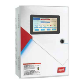
- Page 1 INSTALLATION AND OPERATION INSTRUCTIONS WITH REPLACEMENT PARTS LIST MC5000 Series Controller Models: MC5300: Controls up to Three Units MC5600: Controls up to Six Units Bard Manufacturing Company, Inc. Manual : 2100-746 Bryan, Ohio 43506 Supersedes: www.bardhvac.com Date: 8-20-20 Page 1 of 55...
-
Page 2: Table Of Contents
Controller Certifications ..........4 Dehumidification Sequence .......24 Getting Other Information and Publications ....4 Cooling System ............5 Mechanical Sequence ........24 MC5000 Series Controller and Accessories ...5 Synchronized Sequence ......25 Installation ................. 6 Humidification Operation ........25 MC5000 Series Controller ..........7 Staging ..............25 Mounting the MC5000 Series Controller ....7... - Page 3 Current software 2 Stage Compressor and Economizer ..28 versions and installation instructions are Table 3 Non-Alternating Logic: 3-Unit System with available on the Bard website at http://www. 2 Stage Compressor and Economizer ..28 bardhvac.com/software-download/ Table 4 MC5000BC Series Alarm Functions ....
-
Page 4: General Information
All internal wiring is complete. Only attach low voltage field wiring to designated terminal strips. Getting Other Information and The MC5000 series is for use with units with or without economizers, can be configured for use Publications with heat pumps and has both humidification and These publications can help when installing the air dehumidification control features. -
Page 5: Cooling System
Control System This Bard control system can be composed of a variety of non-PLC operated Bard wall-mount air conditioners or heat pump model offerings. The MC5300 controller can be matched with up to a maximum of three wall-mount air conditioners or heat pumps. The MC5600 controller can be matched with up to a maximum of six wall-mount air conditioners or heat pumps. -
Page 6: Installation
INSTALLATION FIGURE 1 Typical MC5000 Series Controller Component Location Secondary I/O Control Board (MC5600 only) Secondary Alarm Board (MC5600-BC only) Display to I/O Cable (All models) Main I/O Control Board (All models) Main Alarm Board (MC5300-BC and MC5600-BC) Temperature/Humidity Sensor Cable... -
Page 7: Mc5000 Series Controller
Mounting the MC5000 Series Controller Disconnect VAC power supplies before servicing. The MC5000 series controller can be installed in any indoor location that has wall space for hanging. It is Failure to do so could result in electric shock suggested that the controller be hung at eye level. Four or death. -
Page 8: Installing Remote Temperature Sensor(S)
Connect one of the wires from the 24 gauge shielded cable to either the REM 1 or REM 2 terminal on the main I/O board (Bard P/N 8612-066). REM 1 can only be used for an additional indoor temperature sensor. REM 2 can be configured to be used for either an indoor or outdoor sensor application. -
Page 9: Engineered Features
Touch Screen The MC5000 series controller incorporates a 3.25" x 6" touch screen interface for user interaction (see Figure 5). It is not necessary to use only fingers on this interface as the display will respond to pressure from almost any type of object. -
Page 10: Main Control Board (Mc5300 And Mc5600)
Main Control Board (All MC5300 and MC5600 Models) Connection points are provided for one to three wall-mount air conditioners or heat pumps. Units can include optional mechanical dehumidification, electric heat strips, economizer and ventilation. Inputs are also provided for theft, vent, generator, emergency off and two remote temperature sensors. The shelter inputs (theft, vent, generator, emergency off and remote sensor 1 and 2) are connected to the main control board next to Unit 3 terminal strip. -
Page 11: Secondary Control Board (Mc5600 Only)
Secondary Control Board (MC5600-C and MC5600-BC Models Only) Secondary Control Board provides connection points for up to three additional wall-mount air conditioners or heat pump units labeled System 4, 5 and 6. All units can include optional mechanical dehumidification, electric heat strips, economizer and ventilation. -
Page 12: Main Alarm Board (Mc5300-Bc And Mc5600-Bc)
Main Alarm Board (MC5300-BC and MC5600-BC Models Only) The main alarm board allows for Normally Open or Normally Closed dry contacts to be used for remote monitoring of equipment and the controller. Shelter NO/NC Unit Lockout NO/NC Emergency Unit Off Alarm Relays Alarm Relays NO/NC Alarm Relay... -
Page 13: Secondary Alarm Board (Mc5600-Bc Only)
Secondary Alarm Board (MC5600-BC Models Only) The main alarm board allows for Normally Open or Normally Closed dry contacts to be used for remote monitoring of equipment and the controller. Unit Power Loss NO/NC Alarm Relays POWER POWER POWER LOSS 6 LOSS 5 LOSS 4 LOCK... -
Page 14: Setup
Not Connected Determines configuration of the O/B terminal 10. REM 2 Temperature Sensor – Indoor Temperature, (energized in cooling or heating). NOTE: All Bard Outdoor Temperature or Not Connected wall-mount heat pumps require the reversing valve to energize in HEATING mode! 11. -
Page 15: System Setup Menu
9. Press UP/DOWN buttons to scroll to number of 7. Press UP/DOWN arrow to select Month. dehumidifier units; press Next button. 8. Press UP/DOWN arrow to select Day. 10. Press Yes or No button to select if humidifier is 9. Press UP/DOWN arrow to select Year. present;... -
Page 16: Comfort Mode Heating Set Points
Comfort Mode Heating Set Points 4. Press UP/DOWN arrow to scroll to Cooling Stage Off Differential Set Point Value. 1. Press Menu button on Home screen. 5. Press Confirm button. 2. Press Set Points button. 6. Press Home button. 3. Press UP/DOWN arrow to scroll to Comfort Mode Heating Set Point. -
Page 17: Humidification Interstage Differential Set Points
Humidification Interstage Differential Low Temperature Alarm Level Set Set Points Points 1. Press Menu button on Home screen. 1. Press Menu button on Home screen. 2. Press Set Points button. 2. Press Set Points button. 3. Press UP/DOWN arrow to scroll to Humidification 3. -
Page 18: Operation
35' cable • Storage temperature range: -22 to 160°F (-30 to (Bard P/N 8408-061) is available that can be remotely 71°C) mounted. Only one temperature/humidity sensor can be connected to the controller at any given time. -
Page 19: Basic Controller Input/Output Specifications
4-6) installed, it can be field installed at any time. Each Unit The Bard part number for the MC5300 alarm board is 8612-068. The Bard part number for R – 24VAC hot the MC5600 alarm board is 8612-069. -
Page 20: Mc5000B W/Enhanced Version Alarm Board
During this time, if either the To disable the MC5000 series controller and shut down temperature moves more than 5° (heating or cooling) or all air conditioners/heat pumps, terminals marked the humidity moves more than 5% (humidification or Emergency Off must be used. -
Page 21: Lead/Lag Rotation
Lead/Lag Rotation Pressing the Advance Lead button on the home screen will cause the lead to advance to the next unit. This may be useful during service and maintenance procedures. Lead unit will be determined by an internal timer and Lead-Lag Changeover Time selected by user. - Page 22 TABLE 1 MC5000 Series Set Points/Defaults/User Settings Record Set Point (SP) or Item Name Current Range Default User Settings Cooling Set Point 4° above Heating SP to 90°F Heating Set Point 32°F to 4° below Cooling SP Comfort Mode Cooling Set Point 4°...
- Page 23 TABLE 1 MC5000 Series Set Points/Defaults/User Settings Record (cont.) Set Point (SP) or Item Name Current Range Default User Settings Emergency Off, Gen Run, High Humidity Emergency Auxiliary Out Configuration Alarm, Dust Alarm or Dehum Active System Setup Items Languages...
-
Page 24: Humidity Control Option
Humidity Control Option Dehumidification Sequence Mechanical Sequence (see Figure 6) The controller will use terminal D for control of the dehumidification operation on each configured unit. The controller will energize D when dehumidification is required. Terminal D will be de-energized once dehumidification is no longer required or available. -
Page 25: Synchronized Sequence
Synchronized Sequence (see Figure 7) The controller will use 50% of the configured units Staging in the MC5000 series controller can be for heating and 50% of the configured units for configured by the user in an alternating or non- cooling for Synchronized Dehumidification. -
Page 26: Heating Staging
Heating Staging NOTE: If a Unit Power Loss or Lock Out Alarm is present, the unit in alarm will not be considered in Heating staging begins when the space temperature staging sequence—it will be skipped. is less than the heating set point. Staging will increase when the space temperature is less than the Adjustable Interstage Differential (.5°... -
Page 27: The Advantages Of Twinning: Pairs
The Advantages of Twinning: Pairs The Advantages of Twinning: Triples Using the same number of units as shown in Figure Using the same number of units and selecting the 9 on page 25 (six units w/economizers) and selecting Triples option in Twinning, the number of stages can be the Pairs option in Twinning, the number of stages can reduced to four and the space temperature narrowed be reduced to six by engaging two units per stage (see... -
Page 28: Cooling Without Economizer
Alternating and Non-Alternating Setup Cooling without Economizer Alternating/Non-Alternating Logic FIGURE 12 The MC5000 series controller offers two staging Cooling without Economizer sequence options: Alternating (default) or Non- Alternating. Unit 3 Alternating Stage 1 Alternating Logic will be the default for this controller. -
Page 29: Alternating Sequence Cooling
FIGURE 13 Alternating Sequence Cooling Stage Unit 1 Unit 2 Unit 3 Alternating the staging will always bring on ALL economizers (when used and conditions allow) before any compressors are started. If no economizers are installed on single stage units, the mechanical cooling will start in sequence. -
Page 30: Twinning: Simultaneous Unit Operation
Twinning: Simultaneous Unit Operation • Paired – Only available with four or six units. Units will operate in pairs. See Figure 15. • Four total units: Units 1 and 2 will stage • Units operate simultaneously: Off ALL Pairs simultaneously and units 3 and 4 will stage Triples simultaneously. -
Page 31: Triples: Simultaneous Unit Operation
Triples: Simultaneous Unit Operation • Units will stage simultaneously in sets of three. Units 1, 2 and 3 will be one set and units 4, 5 and See Figure 16. 6 will be the second set. Using groups of three for the purpose of staging can •... -
Page 32: Alarm Functionality
Alarm Functionality Emergency Off Alarm If Emergency Off input becomes active, an Emergency All alarms shall have a 5-second delay (alarm criteria Off alarm will be triggered. All outputs to units (W1, must be met for 5 seconds) prior to triggering alarm W2, EC, Y1, Y2, G O/B, A, D and H) will be de- to prevent nuisance alarming. - Page 33 HVAC Compressor Lockout Alarm Output Logic only will block the logging of the alarm into the alarm log and prevent alarm from being listed If the LOR input for any configured unit becomes in the Active Alarms list. active, an HVAC Compressor Lockout alarm will be triggered.
-
Page 34: Test Mode
System Test is active. Once The MC5000 series controllers have remote the timer expires for a stage in the System test, the connectivity available utilizing an Ethernet connection... -
Page 35: Webpage Ip Configuration
SD Card Slot – The SD card must be a micro SD card (FAT format only). FIGURE 18 Webpage IP Configuration Setup Button on MC5000 Series Home Screen NOTE: If the initial network settings configuration are to be done via the webpage, an Ethernet... -
Page 36: Webpages
Webpages Webpage Navigational Side Panel Webpage access requires a default username (admin) and password (bard); after logging in, the webpage prompts user to change the password to promote security. Usernames, passwords, and access levels can also be changed on the User Management page. -
Page 37: Modbus
Modbus some of the controller settings without a password. Any access control to the Modbus will be dependent upon To enable Modbus, the user will need to access the the network used to access the controller. Adjustable webpages and enable the feature on the Modbus settings via Modbus are limited to set point type Configuration page located under the Administration configuration and is intended to be primarily used to... - Page 38 Holding High Humidity Alarm Set point int16_t 65 - 95 % RH Register Holding Low Humidity Alarm Set point int16_t 0 - 80 % RH Register Holding Low Temperature Alarm Set point int16_t 28 - 65 °F Register Holding High Temperature 1 Alarm Set point int16_t 70 - 120 °F Register...
- Page 39 Generator Run Alarm 0 (OFF) - 1 (ON) Theft Alarm 0 (OFF) - 1 (ON) Emergency Ventilate Alarm 0 (OFF) - 1 (ON) Local Temperature/Humidity Sensor 0 (OFF) - 1 (ON) Disconnect High Humidity Alarm 0 (OFF) - 1 (ON) Low Humidity Alarm 0 (OFF) - 1 (ON) System 1 - W1 - Electric Heat - Stage 1...
- Page 40 System 3 - Y2 - Compressor - Stage 2 0 (OFF) - 1 (ON) System 3 - G - Blower 0 (OFF) - 1 (ON) System 3 - O/B - Reversing Valve 0 (OFF) - 1 (ON) System 3 - A Terminal 0 (OFF) - 1 (ON) System 3 - D - Mechanical Dehum 0 (OFF) - 1 (ON)
- Page 41 System 5 - Compressor Lockout 0 (OFF) - 1 (ON) System 5 - Dust 0 (OFF) - 1 (ON) System 6 - W1 - Electric Heat - Stage 1 0 (OFF) - 1 (ON) System 6 - W2 - Electric Heat - Stage 2 0 (OFF) - 1 (ON) System 6 - Y1 - Compressor - Stage 1 0 (OFF) - 1 (ON)
-
Page 42: Connections Diagrams
CONNECTION DIAGRAMS TABLE 6 Connection Diagram Selection Table Units with CRV-F or Units with CRV-F or ERV, ERV, No Economizer Economizer/ System Type Model Series No Economizer with without No Balanced Climate Balanced Climate Balanced Climate A/C with Figure 20 Figure 21 Figure 22... - Page 43 FIGURE 20 W**A SERIES UNIT WITH CRV-F, ERV AND W**A/W**L Series Unit with CRV-F or ERV and No Ventilation or Balanced Climate NO VENTILATION OR BALANCED CLIMATE W**A SERIES UNIT Balanced 24VAC Climate Disable Ventilation Filter Emergency Factory Jumper Field Jumper Switch Alarm Shutdown...
- Page 44 W**A SERIES UNIT WITH CRV-F, ERV, OR NO VENTILATION FIGURE 21 AND BALANCED CLIMATE OPERATION W**A/W**L Series Unit with CRV-F or ERV and No Ventilation with Balanced Climate Remove W**A SERIES UNIT 24VAC Emergency Balanced Filter Ventilation Shutdown Climate Y1-Y2 Switch Alarm Field Jumper...
- Page 45 FIGURE 22 W**A SERIES UNIT WITH ECONOMIZER W**A/W**L Series Unit with Economizer W**A SERIES UNIT 24VAC Emergency Filter Shutdown Switch Alarm Factory Jumper (Optional) Relay LOW VOLTAGE B/W1 TERMINAL STRIP W1 W2 EC Y1 G O/B FILTER DUST LOR AUX IN EIN NO C NC AUX OUT MC-5300: SYSTEM 1-3...
- Page 46 FIGURE 23 W**H SERIES UNIT WITH CRV-F, ERV, OR NO VENTILATION W**H Series Unit with CRV-F or ERV and No Ventilation or Balanced Climate W**H SERIES UNIT Balanced 24VAC Climate Disable Ventilation Filter Emergency Factory Jumper Field Jumper Switch Alarm Shutdown (Optional) Relay...
- Page 47 W**H SERIES UNIT WITH CRV-F, ERV, OR NO VENTILATION FIGURE 24 AND BALANCED CLIMATE OPERATION W**H Series Unit with CRV-F or ERV and No Ventilation with Balanced Climate Remove W**H SERIES UNIT 24VAC Emergency Balanced Filter Ventilation Shutdown Climate Y1-Y2 Switch Alarm Field Jumper...
- Page 48 FIGURE 25 W**H SERIES UNIT WITH ECONOMIZER W**H Series Unit with Economizer W**H SERIES UNIT 24VAC Emergency Filter Shutdown Switch Alarm Factory Jumper (Optional) Relay LOW VOLTAGE B/W1 TERMINAL STRIP W1 W2 BC Y1 G O/B FILTER DUST LOR AUX IN EIN NO C NC AUX OUT MC-5300: SYSTEM 1-3...
- Page 49 FIGURE 26 2-STAGE W*SA* SERIES UNIT 2-Stage W*SA* Series Unit with CRV-F or ERV and No Ventilation or Balanced Climate WITH CRV-F, ERV, NO VENTILATION, AND NO BALANCED CLIMATE Emergency Balanced W*SA* SERIES UNIT Shutdown Climate Disable 24VAC Ventilation Filter Factory Jumper Factory Jumper Field Jumper...
- Page 50 2-STAGE W*SA* SERIES UNIT FIGURE 27 WITH BALANCE CLIMATE OPERATION AND 2-Stage W*SA* Series Unit with ERV and Balanced Climate and No CRV-F or Ventilation NO CRV-F OR ECONOMIZER Remove W*SA* SERIES UNIT 24VAC Emergency Balanced Filter Ventilation Shutdown Climate Y2-Y3 Switch Alarm Field Jumper...
- Page 51 FIGURE 28 2-STAGE W*SA* SERIES UNIT 2-Stage W*SA* Series Unit with Economizer WITH ECONOMIZER W*SA* SERIES UNIT 24VAC Emergency Filter Shutdown Switch Alarm Units w/ Economizer Factory Jumper (Optional) Relay must have jumper installed LOW VOLTAGE B/W1 TERMINAL STRIP W1 W2 EC Y1 G O/B FILTER DUST LOR AUX IN EIN...
-
Page 52: Troubleshooting
TROUBLESHOOTING Checking Remote Temperature Sensor (P/N 8301-095) Outside Unit Circuit 1. Disconnect temperature sensor from board. 4. If sensor resistance reads very low, sensor is shorted and will not allow proper control. 2. Use an ohmmeter to measure the resistance of the sensor. -
Page 53: Troubleshooting Alarms
Troubleshooting Alarms Low Temp Alarm This alarm indicates that there is a lower space temperature than is desired. The space temperature should be verified and compared to the controller reading. If the space temperature reading is incorrect ensure there is no offset applied and then the wiring to the temperature sensors installed should be verified. - Page 54 Ventilation Alarm This alarm indicates that the Vent inputs have continuity. The function of the device connected to the Vent inputs should be verified first. If all device functionality is correct and the alarm is still present the wiring between the device and controller should be checked. Prior to replacing the I/O board all wiring should be removed from the Vent inputs.
-
Page 55: Mc5000 Replacement Parts List
MC5000 SERIES CONTROLLER REPLACEMENT PARTS LIST Dwg. No. Part No. Description 8612-065 Display Board w/Ethernet 8612-066 Main I-O Board SEXP-1026 8612-067 Secondary I-O Board 8612-068 Main Alarm Board SEXP-1026 8612-069 Secondary Alarm Board 8301-092 Bezel Front 8301-093 Bezel Back 8301-094...