Table of Contents
Advertisement
®
Installation, Operation and Maintenance Manual
Please read and save these instructions for future reference. Read carefully before attempting to assemble, install,
operate or maintain the product described. Protect yourself and others by observing all safety information. Failure
to comply with instructions could result in personal injury and/or property damage!
General Safety Information
Only qualified personnel should install this unit.
Personnel should have a clear understanding of these
instructions and should be aware of general safety
precautions. Improper installation can result in electric
shock, possible injury due to coming in contact with
moving parts, as well as other potential hazards. Other
considerations may be required if high winds or seismic
activity are present. If more information is needed,
contact a licensed professional engineer before moving
forward.
1. Follow all local electrical and safety codes, as
well as the National Electrical Code (NEC), the
National Fire Protection Agency (NFPA), where
applicable. Follow the Canadian Electrical Code
(CEC) in Canada.
2. The rotation of the supply fan wheel is critical. It
must be free to rotate without striking or rubbing
any stationary objects.
3. Motor must be securely and adequately grounded.
4. Do not spin fan wheel faster than the maximum
cataloged fan rpm. Adjustments to fan speed
significantly affects motor load. If the fan RPM is
changed, the motor current should be checked
to make sure it is not exceeding the motor
nameplate amps.
5. Do not allow the power cable to kink or come in
contact with oil, grease, hot surfaces, or chemicals.
Replace cord immediately if damaged.
6. Verify that the power source is compatible with
the equipment.
7. Never open fan access doors while the fan
is running.
®
DANGER
Always disconnect power before working
on or near a unit. Use appropriate lockout
tagout procedures to prevent accidental
power up.
CAUTION
When servicing the unit, motor may be hot
enough to cause pain or injury. Allow motor
to cool before servicing.
FOR YOUR SAFETY
If you smell gas:
• Open windows.
• Extinguish any open flame.
• Do not try to light any appliance.
• Do not touch electrical switches.
• Leave the building immediately.
• Immediately call your gas supplier.
• If you cannot reach your gas supplier, call
the fire department.
FOR YOUR SAFETY
The use and storage of gasoline or other
flammable vapors and liquids in open
containers in the vicinity of this appliance
is hazardous.
WARNING
Improper installation, adjustment, alteration,
service or maintenance can cause
property damage, injury or death. Read the
installation, operating and maintenance
instructions thoroughly before installing or
servicing this equipment.
Document 481153
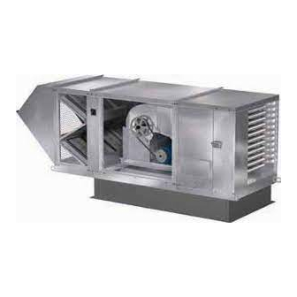
Model IGX
Make-Up Air Unit
Model IGX Make-Up Air
1
Advertisement
Table of Contents

Related Manuals for Greenheck IGX Series


Summary of Contents for Greenheck IGX Series
- Page 1 Document 481153 Model IGX Make-Up Air Unit ® Installation, Operation and Maintenance Manual Please read and save these instructions for future reference. Read carefully before attempting to assemble, install, operate or maintain the product described. Protect yourself and others by observing all safety information. Failure to comply with instructions could result in personal injury and/or property damage! DANGER Always disconnect power before working...
-
Page 2: Table Of Contents
Table of Contents General Start-Up: Indirect Gas-Fired Heating Receiving ........3 Optional Features Handling . -
Page 3: General
General temperature. Leave coverings loose to permit air Receiving circulation and to allow for periodic inspection. This product may have been subject to road salt The unit should be stored at least 3½ in. (89 mm) off during transit. If so, immediately wash off all visible the floor. -
Page 4: Model Number Code
General Model Number Code The model number code provides basic identification of the unit. The serial number can be used by the manufacturer’s representative or the factory to identify the specific unit configuration. The serial number of the unit must be provided when consulting the manufacturer’s representative or the factory. Model Number Code IGX - P1 20 - H22 - MF - C Furnace Input... -
Page 5: Installation
Installation Required Clearances Clearance to Combustibles Service Clearances Clearance to combustibles is defined as the minimum Service clearances are factory recommendations for distance required between the unit and adjacent ease of servicing. All deviations must still adhere to combustible surfaces to ensure the adjacent surface clearance to combustibles requirements. -
Page 6: Duct Sizes
Installation Duct Sizes See charts for duct sizes and straight duct lengths recommended for optimal performance based on AMCA Publication 201-90. Using duct sizes less than recommended will affect fan performance. Follow good duct installation practices for the remaining ductwork. Down Discharge End Discharge Furnace Size... -
Page 7: Indoor Unit Mounting
Installation Indoor Unit Mounting Hanging Floor Mounted When suspending a unit indoors, adequate structural 1. Install Unit support is required. Design of the support structure Use a crane and a set of is the responsibility of the installing contractor and/ spreader bars hooked to or the structural engineer. -
Page 8: Venting Connection Location-Forward Curved
Installation Indoor Unit Mounting Venting Connection Location - Forward Curved Exhaust Air Outlet Combustion Air Intake Airflow Concentric kit Connection Size Flue Connection Furnace Size (diameter in From Furnace to Kit to Outdoors Housing Size inches) (MBH) Exhaust Intake Exhaust Intake Exhaust Intake... -
Page 9: Venting Connection Location-Mixed Flow
Installation Indoor Unit Mounting Venting Connection Location - Mixed Flow Exhaust Air Outlet Combustion Air Intake Airflow Concentric kit Connection Size Flue Connection Furnace Size (diameter in From Furnace to Kit to Outdoors Housing Size inches) (MBH) Exhaust Intake Exhaust Intake Exhaust Intake... -
Page 10: Outdoor Unit Mounting
Installation Outdoor Unit Mounting Standard Curb 1. Install Curb and/or Equipment/Leg Support(s) 2. Install Ductwork Position curb and/or equipment/leg support(s) on Follow good duct practices for all ductwork. Install the roof (reference the unit submittal for placement ductwork in accordance with SMACNA and AMCA in relation to the unit). -
Page 11: Standard Curb
Installation Outdoor Unit Mounting Standard Curb (continued) 4. Install Unit 5. Assemble and Attach Shipped Loose Use a crane and a set of spreader bars hooked to the Modules factory lifting lugs to lift and position the unit on the Using sheet metal screws, assemble optional shipped curb/equipment support(s). -
Page 12: Combination Curb
Installation Outdoor Unit Mounting Combination Curb 1. Install Curb and Equipment/Leg Support(s) 2. Install Combination Curb Adaptor Position curb and equipment/leg support(s) on the roof Install combination curb adaptor over curb, fasten (reference the unit submittal for placement in relation adapter to curb using appropriate methods. - Page 13 Installation Outdoor Unit Mounting Combination Curb (continued) 3. Install Ductwork 5. Install Exhaust Fan Follow good duct practices for all ductwork. Install Fasten exhaust fan to curb extension using appropriate ductwork in accordance with SMACNA and AMCA methods. Installing the exhaust fan prior to the guidelines, NFPA 96 and local codes.
-
Page 14: Combination Curb
Installation Outdoor Unit Mounting Combination Curb (continued) 8. Assemble and Attach Shipped loose Modules Using sheet metal screws, assemble optional shipped loose modules. Fasten the cover seams and vertical panels on each module securely. Some weatherhoods may ship disassembled. Detailed assembly instructions ship with the weatherhood. -
Page 15: Slab Mounted
Installation Outdoor Unit Mounting Slab Rail 1. Pour Concrete Slab 1. Install Rails Pour the concrete slab. Make The rails must be located the slab one foot larger than around the perimeter the unit on all sides. The slab of the base unit on must be capable of supporting all four sides. -
Page 16: Optional Component Mounting
Installation Optional Component Mounting Evaporative Cooling Module Diffuser Note: Small evaporative cooling module will ship The location of the discharge diffuser is critical for attached to the base unit from the factory and will optimum performance of the system. not require any additional fixation to the base unit as Using self-tapping screws, attach diffuser to illustrated below. -
Page 17: Line Voltage Electrical Wiring
Installation Line Voltage Electrical Wiring Before connecting power to the unit, read and 5. Wire Evaporative Cooling Pumps understand the following instructions and wiring Reference the unit wiring diagram attached to the diagrams. Complete wiring diagrams are attached on inside of the unit control center door. Locate the “Evap the inside of the control center door(s). -
Page 18: Optional Electrical Accessory Wiring
Installation Optional Electrical Accessory Wiring Evaporative Cooling Module Fire Suppression System The building fire suppression system is typically wired 1. Auto Drain and Fill Valves to shut down the unit in the event of a fire. A normally The unit may have been provided with the auto drain closed (NC) contact should be wired in series with and fill option. -
Page 19: Remote Panel
Installation Optional Electrical Accessory Wiring Remote Panel Room Temperature Sensing Devices The optional remote panel is shipped separately for field installation and wiring. One of the following sensors or equivalent may have 24 VAC control wiring must be connected between the been provided and will require field wiring. -
Page 20: Piping
Installation Piping All gas piping must be installed in accordance with 3. Install Additional Regulator if Required the latest edition of the National Fuel Gas Code ANSI/ When the supply gas pressure exceeds the maximum Z223.1 and any local codes that may apply. In Canada, gas pressure shown on the indirect gas nameplate, an the equipment shall be installed in accordance with additional regulator is required to reduce the pressure. -
Page 21: Optional Evaporative Cooling Module
Installation Piping Optional Evaporative Cooling Module Recirculating Pump Single Pass Supply Line Supply Line Sump Overflow VALVE A Field-Supplied Supply Solenoid Sump Drain Supply Line Valve Field-Supplied (normally closed) Drain Line Valve Drain Line Overflow VALVE B Trap Trap Supply Line Drain Solenoid (normally open) Drain Line Auto Drain and Fill... - Page 22 Installation Piping Optional Evaporative Cooling Module (continued) 1. Install the Water Supply Line 3. Check/Adjust Water Level Supply line opening requirements vary by unit size and Check the water level in the sump tank. The water level arrangement. Connect the water supply line to the float must be above the pump intake and below the overflow.
-
Page 23: Optional Split Direct Expansion Coil
Installation Piping Optional Split Direct Expansion (DX) Coil Guidelines for the installation of direct expansion (DX) Coil Suction Header Distributor cooling coils have been provided to ensure proper Liquid Line Equalizer Line performance and longevity of the coils. These are general guidelines that may have to be tailored to Nozzle meet the requirements of a specific installation. -
Page 24: Optional Chilled Water Coil
Installation Piping Optional Chilled Water Coil Guidelines for the installation of chilled water cooling 2. Connect the Supply & Return Lines coils have been provided to ensure proper performance Connect the supply and return lines as shown. and longevity of the coils. These are general guidelines 3. -
Page 25: Optional Components
Installation Optional Components Building Pressure Control Building Static Pressure Sensor (with microprocessor) 1. Mounting Pressure Sensor Using the factory provided bracket, mount the pressure The controller will modulate the supply fan based upon sensor outside of the a comparison of the building static pressure set point building. -
Page 26: Supply Fan Fan Identification
Supply Fan Fan Identification The fan type must be identified before performing the Mixed Flow Plenum Fans supply fan pre-start checks and start-up. The unit was Mixed flow plenum fans are single width, single inlet supplied with one of three fan options. fans. -
Page 27: Pre-Start Checks
Supply Fan Pre-Start Checks 5. Check Plenum Fan Radial Overlap, Offset, TOOLS REQUIRED Gap, and Wheel Alignment (if applicable) • Voltage Meter (with wire probes) Backward-Curved Plenum Fan Radial Overlap • Amperage Meter Proper wheel and inlet cone overlap is shown in the •... -
Page 28: Start-Up
Supply Fan Start-Up 1. Check Electrical Connections 4. Check for Vibration Tug test all internal electrical connections to ensure no Check for unusual noise, vibration or overheating of the loose connections occurred during shipment. bearings. Excessive vibration may be experienced during the 2. -
Page 29: Start-Up: Indirect Gas-Fired Heating
Start-Up: Indirect Gas-Fired Heating Optional Features Variable Air Volume (VAV) Pressure Indicating Pressure Setting Complete the Supply Fan Pre-Start Checks and Start- Needle Needles Up sections in this IOM before proceeding. For maintenance issues associated with a variable frequency drive (VFD), consult the drive’s manual supplied with the unit. -
Page 30: Recirculation Operation
Start-Up: Indirect Gas-Fired Heating Optional Features Recirculation Operation Pressure Indicating Pressure Setting The recirculation operation option is recommended Needle Needles when the ventilation equipment provides the primary source of heating for the space or when exhaust fan tracking is required. Control strategies include 2-position option and modulating options. -
Page 31: Start-Up: Optional Features Evaporative Cooling Module
Start-Up: Optional Features Evaporative Cooling Module Note: For single pass, complete steps 1, 4, 5 and 7. Adjust the Water Bleed-Off Rate The water bleed-off rate is dependent on the water’s 6 only. mineral content. After two weeks of service, adjust 1. -
Page 32: Other
Start-Up: Optional Features Other Building Freeze Protection 2. Close and secure the filter compartment door. 3. Check to see if there is power at the alert signal This option is intended to disable the unit supply fan leads (refer to electrical diagram). in the event the discharge temperature falls below 4. -
Page 33: Sequence Of Operation
Sequence of Operation If the unit has a microprocessor, reference the OPTIONAL COOLING supplemental Microprocessor Controller for Make-Up Optional Cooling Contact (S4) Closed Air Reference Guide for more information. • Power passes to normally open fan relay (RF or OPTIONAL EXHAUST ST1) which is energized and closed. -
Page 34: Optional Variable Volume
Sequence of Operation Freeze Condition External Signal VFD Control • If the incoming air temperature is below the • When the supply fan relay (RF) is energized, the evaporative cooling module freeze sensor (FRZ) set normally open supply fan relay (RF) contacts are point, the freeze sensor (FRZ) contacts will open, closed. -
Page 35: Optional Night Setback
Sequence of Operation Potentiometer Recirculation Control OPTIONAL NIGHT SETBACK • Power passes to inlet damper which opens. Night Setback Schedule • When damper is fully opened, normally open • The night setback schedule is established within damper limit switch (DL1) closes. the programmable thermostat on the remote panel. -
Page 36: Maintenance General
Maintenance General Bearings (if applicable) CAUTION Fan bearings are carefully selected to match the Lock-out the gas and the electrical power to the maximum load and operating conditions of the specific unit before performing any maintenance or service class, arrangement and fan size. The instructions operations to this unit. -
Page 37: Motors
Maintenance General Motors Evaporative Cooling Module Motor maintenance is generally limited to cleaning and The media must periodically be brushed lightly with lubrication (where applicable). a soft bristle brush in an up and down motion while flushing with water. This aids in reducing the amount of Limit cleaning to exterior surfaces only. -
Page 38: Seasonal: Heating/Cooling
Maintenance Seasonal: Heating/Cooling Start-Up Flushing Coils Manufacturer recommends the use of inhibited glycol Repeat Supply Fan, Pre-Start Checks and Start-Up; (such as propylene or ethylene) to flush water coils Pre-Start: Indirect gas-Fired Heating; and Start-Up: to protect against freezing. Additionally, the use of Indirect gas-Fired Heating sections in this IOM. -
Page 39: Burners And Orifices
Maintenance Seasonal: Heating/Cooling Burners and Orifices Before each heating season, examine the burners and gas orifices to make sure they are clear of any debris such as spider webs, etc. Clean burner as follows: • Turn off both electrical and gas supplies to the unit. •... -
Page 40: Troubleshooting Supply Fan
Troubleshooting Supply Fan Problem: Fan does not operate. Line voltage across L1 & L2, L2 & L3, Main incoming power not connected. Connect proper supply and L1 & L3 on main disconnect (DS1)? power to unit. Line voltage across T1 & T2, T2 & T3, Main disconnect (DS1) open or defective. - Page 41 Troubleshooting Supply Fan Problem: Motor overamps. Motor voltage correct? Provide proper power supply. Reference Supply Fan, Start-Up. Fan rotation correct? Reverse fan rotation. Reference Supply Fan, Start-Up. Adjust drives or increase external static pressure as needed. Air volume too high? Reference Supply Fan, Start-Up.
-
Page 42: Furnace
Troubleshooting Furnace For complete furnace information reference the Indirect Gas-Fired Heat Modules IOM. Available turndown control options include: Electronic Modulation 4:1- uses modulating valve and furnace controller Single Furnace *High turndown uses a 4:1 modulating Unit valve with a proprietary manifold and furnace controller 8:1- uses one 4:1 modulating furnace with furnace controller and one 2-stage furnace... -
Page 43: Evaporative Cooling
Troubleshooting Evaporative Cooling Problem: Evaporative Cooling Module Does Not Operate - Recirculating Pump Control Is fan operating correctly? Refer to Troubleshooting, Supply Fan. Cool switch (S4) off. Turn cool switch (S4) on. Cool switch not wired. Wire cool switch (S4). 24 VAC between terminals Y1 and C If a cool switch is not required and a cooing inlet air sensor is provided, place jumper from R to Y1 to allow the cooling to enable... - Page 44 Troubleshooting Evaporative Cooling Problem: Evaporative Cooling Module Does Not Operate - Auto Drain and Fill Control Is fan operating correctly? Refer to the Troubleshooting, Supply Fan. Cool switch (S4) off. Turn cool switch (S4) on. Cool switch not wired. Wire cool switch (S4). 24 VAC between terminals Y1 and C If a cool switch is not required and a cooing inlet air sensor is provided, place jumper from R to Y1 to allow the cooling to enable...
-
Page 45: Evaporative Cooling
Troubleshooting Evaporative Cooling Problem: Evaporative Cooling Module Does Not Operate - Single Pass Control Is fan operating correctly? Refer to the Troubleshooting, Supply Fan. Cool switch (S4) off. Turn cool switch (S4) on. Cool switch not wired. Wire cool switch (S4). 24 VAC between terminals Y1 and C (If a cool switch is not required and a cooing inlet air sensor is provided, place jumper from R to Y1 to allow the cooling to enable... -
Page 46: Reference
Reference Typical Control Center Layout Blower Control Center 16. Cooling Relay (Optional) - Allows power to pass to cooling controls. 14 15 17. Reset Timer (Optional) - Resets cooling system to run a time interval. 18. Auto Drain Relay (Optional) - Assures supply pump does not operate during drain interval. -
Page 47: Start-Up Checklist
Reference Start-Up Checklist Unit Model Number ________________________________ Start-Up Indirect Gas (e.g. IGX-120-H32) Furnace 1 Determine furnace control type: Unit Serial Number _________________________________ (e.g. 10111000) High Turndown - 8 Stage - 4:1 Modulation Check supply gas pressure Start-Up Date _____________________________________ ________ Maximum Start-Up Personnel Name __________________________ ________ Minimum ________ Actual... -
Page 48: Maintenance Log
As a result of our commitment to continuous improvement, Greenheck reserves the right to change specifications without notice. Product warranties can be found online at Greenheck.com, either on the specific product page or in the literature section of the website at Greenheck.com/Resources/Library/Literature.