Table of Contents
Advertisement
Quick Links
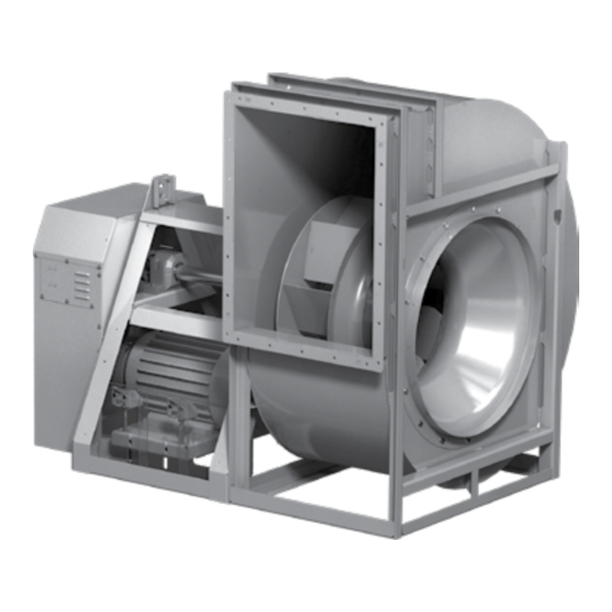
Document 479870
Model USF
Series 100, 300 and 500
®
Universal Single Width Fans
Installation, Operation and Maintenance Manual
Please read and save these instructions for future reference. Read carefully before attempting to assemble,
install, operate or maintain the product described. Protect yourself and others by observing all safety
information. Failure to comply with these instructions will result in voiding of the product warranty and may
result in personal injury and/or property damage.
Series 100
Series 500
Series 300
Direct Drive
Direct Drive
Belt Drive
Series 100
Series 500
Belt Drive
Belt Drive
NOTE
For further details on safety practices involving industrial and commercial fans, refer to AMCA Publication 410.
Universal Single Width Fans
1
®
Advertisement
Table of Contents

Related Manuals for Greenheck 100 Series


Summary of Contents for Greenheck 100 Series
- Page 1 Document 479870 Model USF Series 100, 300 and 500 ® Universal Single Width Fans Installation, Operation and Maintenance Manual Please read and save these instructions for future reference. Read carefully before attempting to assemble, install, operate or maintain the product described. Protect yourself and others by observing all safety information.
-
Page 2: Table Of Contents
Table of Contents General Safety Information � � � � � � � � � � � � � � � � � � � � � � � � � � � � � � � � � � � � � � � � � � � � � � � � � � � � � � � � � � � � � � � � � � �3 General Information �... -
Page 3: General Safety Information
General Safety Information Only qualified personnel should install this fan. Personnel should have a clear understanding of these instructions and should be aware of general safety precautions. Improper installation can result in electric shock, possible injury due to coming in contact with moving parts, as well as other potential hazards. Other considerations may be required if seismic activity is present. -
Page 4: General Information
General Information To ensure a successful installation, the instructions in this manual should be read and adhered to. Failure to comply with proper installation procedures may void the warranty. Unit and System Identification Tags Each fan has a permanently affixed manufacturer’s engraved metal nameplate containing the model number and individual serial number. - Page 5 Storage • Rotate fan wheel monthly and purge bearings once every three months. • Energize fan motor once every three months. • Store belts flat to keep them from warping and stretching. • Store unit in a location which does not have vibration. •...
-
Page 6: Installation
Installation Move the fan to the desired location. Check and tighten fasteners throughout the unit and then fasten securely through mounting holes provided in the base angles. The unit must be set level (shimming may be necessary). Flexible duct connections and vibration isolators should be used where noise is a factor. The motor voltage and ampere rating must be checked for compatibility with the electrical supply prior to final electrical connection. - Page 7 Inlet Spin - Inlet spin is a frequent cause of reduced fan POOR GOOD 3/4 to 3/4 to performance. The change in fan performance is a function one fan One fan one fan wheel diameter wheel diameter diameter of the intensity of spin and not easily defined. The best solution is proper duct design and airflow patterns.
-
Page 8: V-Belt Drives
Measuring Belt Tension (FA/127-11) www.greenheck.com/resources/library/application-articles Alignment of Pulleys and Belts Check pulleys and belts for proper alignment to avoid unnecessary belt wear, noise, vibration and power loss. -
Page 9: Vibration
Position the level on the isolation base, not the fan shaft, for proper leveling. Additionally, the motor and fan shafts must be level and parallel relative to each other for proper alignment. Mounting bases and Vibration Isolation www.greenheck.com/resources/library/literature Universal Single Width Fans ®... -
Page 10: Rigging And Lifting
Rigging and Lifting Fans are to be rigged and moved by the lifting brackets provided or by the skid when a forklift is used. Location of the brackets varies by model and size. Handle in such a manner as to keep from scratching or chipping the coating. -
Page 11: Field Coating Touch-Up Procedure
Field Coating Touch-Up Procedure for Scratched Areas Standard coating and color is RAL 7023 Concrete Grey. The procedure outlines the correct method for repairing minor scratches in the coating. TOUCH-UP PAINT REPAIR KIT CONTENTS 1. Scuff affected area to be repaired using medium sandpaper (provided) or medium Scotch Brite™... -
Page 12: Radial Gap, Overlap And Wheel Alignment
Radial Gap, Overlap and Wheel Alignment Wheels must rotate freely and not rub on the Radial Gap and Overlap Dimensions inlet cone. Models USF with BI (backward- Series 100 Backward-Inclined inclined) or AF (airfoil) wheels overlap the Overlap Overlap Direct Drive Overlap inlet cone. -
Page 13: Unit Start-Up
wheel on the scroll I will incorporate the I will incorporate the without creating wheel on the scroll wheel on the scroll an additional without creating without creating Airflow an additional layer in the an additional Airflow layer in the InDesign file. - Page 14 These models are selectable with different speed control options. Please review your submittal to see how the unit was selected to be controlled. IOMs for these control types can be found at www.greenheck.com/vari-green. Integrated VFD - Models selected as single phase above 3/4 HP will be provided with a mounted, wired and programmed VFD controlling a premium induction motor.
-
Page 15: Variable Frequency Drive Operation
6. If additional adjustment is required, press Stop and repeat steps 3-4. Troubleshooting USF Series 100, Direct Drive, Backward-Inclined – Variable Speed Vari-Green Controls - see www.greenheck.com/vari-green for more details. To start, reference IOM# 473681. Vari-Green Motor and Controls (#473681 IOM) www.greenheck.com/resources/library/literature - download the Yaskawa Manual for AC Drive - J1000 at www.yaskawa.com OR call 1-847-887-7457,... -
Page 16: Routine Maintenance And Operation
For more information about measuring belt tension, refer to Product Belt Span Application Guide, FA/127-11, Measuring Belt Tension, found online at greenheck.com in the library section. Check belt tension two times during the first 24 hours of operation and periodically thereafter. Universal Single Width Fans... - Page 17 Model USF Series 100, Belt Drive – Belt Adjustment Belts on the USF series 100 are adjusted from the exterior of the fan. The end cover must be removed so that the belt(s) can be inspected and checked for proper tension. 1.
-
Page 18: Bearing Replacement
Bearing Replacement For Arrangements 1, 3, 8, 9 or 10 Bearing Installation The intent of this procedure is to allow a field service 1. Before installing, read bearing manufacturers’ technician to replace bearings with the fan remaining procedures. Before putting the new bearings on in place in its intended application. -
Page 19: Parts List
Parts List Each fan bears a manufacturer’s nameplate with model number and serial number embossed. This information will assist the local manufacturer’s representative and the factory in providing service and replacement parts. Before taking any corrective action, make certain unit is not capable of operation during repairs. CAUTION CAUTION A fan manufactured with an explosion resistant... - Page 20 • Series 500 Belt Drive Shaft Pulley (driven) Drive Side Bearing Opposite Drive Side Bearing Belt(s) Fan Shaft Heat Slinger* Rub Ring* Shaft Seal* Motor Pulley Drive Frame Assembly (driver) Motor Adjustable Motor Plate Scroll Housing Punched Outlet Flange* Companion Outlet Flange* Wheel Inlet Cone Outlet Guard*...
- Page 21 • Series 300 Shaft Pulley (driven) Motor Pulley Belt(s) (driver) Drive Side Bearing Weatherhood Opposite Drive Side Bearing Components Fan Shaft Heat Slinger* Rub Ring* Shaft Seal* Drive Frame Assembly Motor Scroll Housing Outlet Flange* Wheel Inlet Cone Outlet Guard* Inlet Flange* Inlet Companion Flange*...
-
Page 22: Warranty Statement
Failure to properly review this checklist and fill out the required information may result in loss of warranty. This document will be used to review field issues. Retain this document for your records. Greenheck Warranty Statement www.greenheck.com/resources/library/literature Universal Single Width Fans... -
Page 23: Troubleshooting
Troubleshooting WARNING AVERTISSEMENT Before taking any corrective action, make certain Avant d’entreprendre toute action corrective, unit is not capable of operation during repairs. s’assurer que l’appareil ne pourra pas fonctionner durant les réparations. Problem Cause Corrective Action Adjust wheel and/or inlet cone. Wheel Rubbing Inlet Tighten wheel hub or bearing collars on shaft. -
Page 24: Installation / Start-Up Checklist
Lock out where necessary Our Commitment As a result of our commitment to continuous improvement, Greenheck reserves the right to change specifications without notice. Specific Greenheck product warranties are located on greenheck.com within the product area tabs and in the Library under Warranties.