Hitachi NEXT Series Instruction Manual
Oil-free rotary screw air compressor
Hide thumbs
Also See for NEXT Series:
- Instruction manual (110 pages) ,
- Service manual (85 pages) ,
- Instruction manual (144 pages)
Table of Contents
Advertisement
INSTRUCTION MANUAL
HITACHI Oil-Free Rotary Screw Air Compressor
Air-Cooled
DSP-90A6N
DSP-90VA6N
Water-Cooled
DSP-90W6N
DSP-90VW6N
Prior to operation of this air compressor,
ensure that all operators read and
u n d e r s t a n d t h i s I N S T R U C T I O N
MANUAL completely, thereby operating
it safely and properly.
Place the INSTRUCTION MANUAL
near the air compressor to make it
available at any time, and refer to it as
the need arises.
DSP-110A6N
DSP-110VA6N
DSP-110W6N
DSP-110VW6N
● This INSTRUCTION MANUAL explains in detail
the important items that require attention;
observed as the following:
● Always observe Instructions of WARNING,
CAUTION and IMPORTANT, as they indicate
considerable risks to safety.
GRAPHIC DESCRIPTIONS:
: I ndicates warnings. If handled
WARNING
improperly, death or severe injury
could result.
: I ndicates cautions. If handled
CAUTION
improperly, injury and/or physical
damage could result.
Air-Cooled
:Indicates air-cooled type.
Water-Cooled
:Indicates water-cooled type.
:Indicates variable speed type.
: I ndicates information that needs
IMPORTANT
attention, other than WARNING and
CAUTION.
: I ndicates a reference page.
Advertisement
Table of Contents
Troubleshooting

Related Manuals for Hitachi NEXT Series


Summary of Contents for Hitachi NEXT Series
-
Page 1: Instruction Manual
INSTRUCTION MANUAL HITACHI Oil-Free Rotary Screw Air Compressor Air-Cooled DSP-90A6N DSP-110A6N DSP-90VA6N DSP-110VA6N Water-Cooled DSP-90W6N DSP-110W6N ● This INSTRUCTION MANUAL explains in detail DSP-90VW6N DSP-110VW6N the important items that require attention; observed as the following: ● Always observe Instructions of WARNING, CAUTION and IMPORTANT, as they indicate considerable risks to safety. - Page 2 How to Use This Instruction Manual ● This Instruction Manual covers the standard models of the Hitachi DSP air compressor. ● This Instruction Manual intended to assist daily operators and maintenance personnel in the installation, operation, control and service of the air compressor.
-
Page 3: Table Of Contents
Contents 1. SAFETY PRECAUTIONS ………………………………………………………………………………………… 2 2. GENERAL DESCRIPTION 2.1 Appearance ……………………………………………………………………… 6 2.2 Components …………………………………………………………………… 8 2.3 Daily Operating Components ……………………………………………… 10 3. OPERATING PROCEDURE 3.1 Instrument Panel ……………………………………………………………… 12 3.2 Start/Stop Operation ………………………………………………………… 14 3.3 How to Use the Liquid Crystal Display (LCD) ... -
Page 4: Safety Precautions
1. SAFETY PRECAUTIONS To ensure safe and proper operation of the air compressor, it is indispensable to carefully read and understand the following warnings and instructions detailed below. These warnings and instructions are attached to the air compressor as shown in the figure below. - Page 5 1. SAFETY PRECAUTIONS WARNING Electric Shock Hazard! ●Before servicing or wiring the air compressor, disconnect the power. This will prevent anyone from turning on the power and causing an elec- tric shock that could lead to severe injury or death. ●Do not allow any unlicensed person to wire the air compres- sor.
- Page 6 1. SAFETY PRECAUTIONS DSP- 90/110W6N Water-Cooled 90/110VW6N WARNING Rotating Parts! ●Keep hands and rods, etc. away from the rotating parts (Cooling fans, etc.) WARNING ●Use caution at all times, when air com- pressor is powered. The air compres- sor may be capable of restarting with- out hitting the START button.
- Page 7 1. SAFETY PRECAUTIONS WARNING Electric Shock Hazard! ●Before servicing or wiring the air compressor, disconnect the power. This will prevent anyone from turning on the power and causing an elec- tric shock that could lead to severe injury or death. ●Do not allow any unlicensed person to wire the air compres- sor.
-
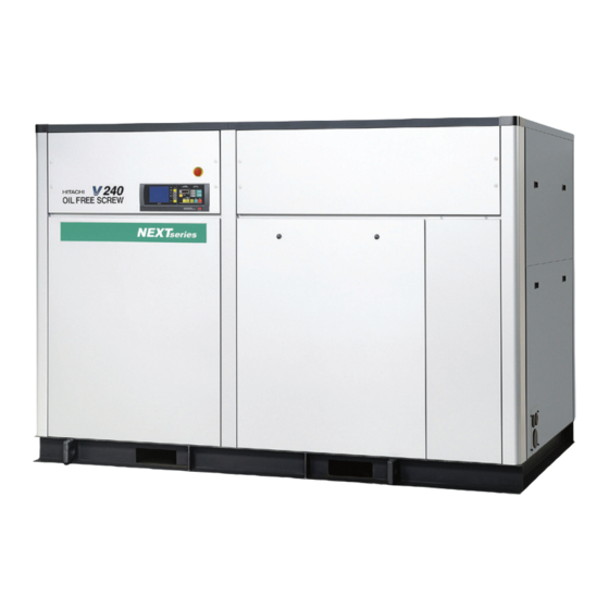
Page 8: Appearance
2. GENERAL DESCRIPTION 2.1 Appearance This section illustrates and describes the major components of the DSP air compressor. Be familiar with the name, location and function of each component before using the DSP air compressor. DSP- 90/110A6N Air-Cooled 90/110VA6N [Front View] Air Exhaust Air Intake (Air Compressor Package) - Page 9 2. GENERAL DESCRIPTION [Appearance] Water-Cooled DSP- 90/110W6N 90/110VW6N [Front View] Air Exhaust Air Exhaust Air Intake (Air Compressor Package) Enclosure This panel discharges the hot air generated E n c l o s u r e p a n e l s in the air compressor.
-
Page 10: Components
2. GENERAL DESCRIPTION [Components] 2.2 Components DSP- 90/110A6N Air-Cooled 90/110VA6N Check valve Aftercooler Discharge pipe (Compressed Intercooler Air Discharge) Air relief valve Enclosure Cooling fan Instrument panel Oil cooler Control panel Hi-precooler Oil mist remover Common base 2nd-stage air end Main motor 1st-stage air end Air intake filter... - Page 11 2. GENERAL DESCRIPTION [Components] DSP- 90/110W6N Water-Cooled 90/110VW6N Aftercooler Air relief valve Discharge pipe Cooling fan (Compressed air discharge) Enclosure Intercooler Instrument panel Control panel Oil mist remover 2nd-stage air end Common base Oil cooler Check valve Main motor 1st-stage air end Air intake filter Oil filter Oil level gauge...
-
Page 12: Daily Operating Components
Oil Level Gauge Lubricating Oil Aftercooler and Intercooler - Condensate Drain Valve Oil: Use genuine Hitachi GL-68 DSP Compressor Oil. ● Verify that air containing condensate is discharged Replace the oil every 8,000h operating hour or every intermittently from the intercooler and aftercooler 2-year, whichever comes earlier. -
Page 13: Cooling Water
2. GENERAL DESCRIPTION [Daily Operating Components] Water-Cooled Cooling Water Control Line Filter [Fixed speed type] ① Stop the cooling water flow when the DSP has ● Check the sight glass on the control line filter to stopped running. make sure that the condensate discharged ②... -
Page 14: Instrument Panel
3. OPERATING PROCEDURE 3.1 Instrument Panel LCD monitor MONITOR Button AUTO light (yellow) RESET Button ON (glowing) when an Displays the operation data, Resets SHUTDOWN Switches the monitor display. automatic operation (an and ALARM screens. various settings, shutdown/ 3.3.1) AUTO operation, a schedul- 3.3.3) alarm information, etc. - Page 15 3. OPERATING PROCEDURE [Instrument Panel] RUNNING MODE Light ● POWER light (yellow): Lights up when the main power is turned on. ● REMOTE light (green): ON (glowing) when the REMOTE button is pressed in Digital Monitor EMERGENCY STOP button order to activate a remote operation. Used for basic settings as well Stops for emergency.
-
Page 16: Start/Stop Operation
When the power is connected, the POWER light turns When the START button is pressed, the START light ON and the following Hitachi logo display appears on turns on and the compressor starts operating. the LCD. After 5 seconds, monitoring display appears;... -
Page 17: How To Use The Liquid Crystal Display (Lcd)
3. OPERATING PROCEDURE [How to Use the Liquid Crystal Display (LCD)] 3.3 How to Use the Liquid Crystal Display (LCD) 3.3.1 How to Move between the Various Displays ■ Monitoring Displays ■ Menu Displays There are three monitoring displays as shown Follow the bottom line message on the display. - Page 18 3. OPERATING PROCEDURE [How to Use the Liquid Crystal Display (LCD)] 3.3.2 Monitoring Displays ■ Monitor Displays during Normal Operation Monitor Display 1 * SAVE VSDA Indicates ECOMODE is activated for fixed speed type. 3.4.8) Displayed when stop is limited for AUTO operation (Standard: no symbol) Monitor Display 2 INTE : Indicates fixed speed type used the standard, 2-step...
- Page 19 3. OPERATING PROCEDURE [How to Use the Liquid Crystal Display (LCD)] 3.3.3 Message Displays ■ Shutdown Messages ① When the shutdown occurs for the compressor, the SHUTDOWN light and shutdown contents on the LCD monitor (contents are displays on the left side and details are displayed on the right side) blink and the compressor stops running.
- Page 20 3. OPERATING PROCEDURE [How to Use the Liquid Crystal Display (LCD)] ■ Messages of Automatic Stop Display When the air compressor stops automatically, the AUTO START light glows or blinks and RESTART display appears. After the air compressor restarts, monitoring display appears again. ●...
- Page 21 3. OPERATING PROCEDURE [How to Use the Liquid Crystal Display (LCD)] ■ Maintenance Notice Messages ① Periodical maintenance A maintenance date is determined by the amount of total operating hours or an elapsed calendar period, whichever comes first. When the maintenance date or time arrives, the maintenance notice message appears on the display under the heading of MESSAGE.
- Page 22 3. OPERATING PROCEDURE [How to Use the Liquid Crystal Display (LCD)] 3.3.4 How to Move within a Menu Display and to Change a Setting The method and procedure for altering settings is displayed using the following as an example. How to MOVE within a [FUNCTION MENU] Display ①...
- Page 23 ⑧ Displays water failure detection conditions for water IMPORTANT cooled compressor. ⑨ Displays status of instantaneous power interruption When contacting the local Hitachi distributor, inform (IPI) restart setting. this information as a based setting status. ⑩ Displays compressor number. (Must be distinguished by number is using communication function.)
- Page 24 3. OPERATING PROCEDURE [How to Use the Liquid Crystal Display (LCD)] Capacity control This function sets the pressures and times for capacity 8. TIME: ⑥ Can set the time to use pressure setting 2. control. Two different combinations (P1 and P2) of When set the value properly, ②...
- Page 25 3. OPERATING PROCEDURE [How to Use the Liquid Crystal Display (LCD)] Operation Data Display Alarm History ① Data can be recorded for a maximum of twelve (12) This display shows a maximum of 6 alarms and times. The 13th recorded data is automatically deleted displays the following information as such: type of and the 1st recorded data is added.
- Page 26 3.3.6. Other Settings Initial Setting 3-Language Display Switch The calendar and clock are set by Hitachi prior to The language of the display can be switched to delivery. To reset the calendar and clock, contact Japanese, English or Chinese by the dip switch on the local Hitachi distributor.
-
Page 27: How To Use The Digital Monitor
3. OPERATING PROCEDURE [How to Use the Digital Monitor] 3.4 How to Use the Digital Monitor 3.4.1 How to Display Operation Status, Shutdown History, and Status of Various Settings All display contents of the digital monitor are linked with the LCD monitor. All of the following display contents can be confirmed by the LCD monitor. - Page 28 3. OPERATING PROCEDURE [How to Use the Digital Monitor] (2) How to Display Shutdown History Use the following procedure to display shutdown history. Discharge pressure display ① Press the SELECT/WIDE button 8 times. “E0.” is the [Latest shutdown] SELECT/WIDE displayed with the shutdown code ( Section 4).
- Page 29 3. OPERATING PROCEDURE [How to Use the Digital Monitor] 3.4.2 How to Set Control Functions ■ Various settings (instantaneous power interruption (IPI), remote operation, capacity control setting, pressure setting, etc.) Switches the display from monitor mode to setting mode (F mode). RESET Displays 000 item of F mode.
- Page 30 3. OPERATING PROCEDURE [How to Use the Digital Monitor] 7 segment Precision/ Function Item Range Default Remarks display unit Control pressure 71 〜 125 1psi F022 setting 1 psi (MPa) (0.5 〜 0.86) (0.01MPa) (0.86) Cut-out pressure 1 71 〜 128 1psi F023 Pressure...
- Page 31 3. OPERATING PROCEDURE [How to Use the Digital Monitor] Use the following procedure to change the pressure 3.4.3 Change of Pressure Setting setting of the capacity control system. ① Switch the display from monitor mode to setting Pres. setting 1 mode (F mode). ② ...
- Page 32 Alter values. (3) To change the Local or remote operation by external contact. ( Contact the local HITACHI distributor/master dealer or representative office.) ① Connect the external contact wiring. ( 8.2) ② Switch the display from monitor mode to setting mode (F mode).
- Page 33 2 is activated. Exter nal selection of Cut-in/Cut-out pressure combination 1 or 2 is an option. (F018-2). Contact the local HITACHI distributor/master dealer or representative office. 3.4.8 ECOMODE Function (only for Fixed speed type) (1) Setting of ECOMODE (Energy Saving Mode) ECOMODE is set OFF on factor y setting.
-
Page 34: Daily Operation Of Air Compressor
● If the air relief valve has blown or a protective device has shutdown the air compressor, investigate the cause of and take corrective action. If there are any questions or comments in taking these actions, contact the local HITACHI distributor/master dealer or representative office. 3.5.1 Preparing the air compressor ①... - Page 35 3. OPERATING PROCEDURE [Daily Operation of Air Compressor] 3.5.3 While Operating the Air Compressor ① Check the LCD for operating pressures and temperatures, and verify that: RUNNING CONTROL RUNNING MODE AUTO Interstage pressure (INTSTG P), oil pressure (OIL PRES), MONITOR REMOTE POWER ALARM 1st stage discharge air temperature (DIS.
-
Page 36: Daily Operation Of Oil Mist Remover
3. OPERATING PROCEDURE [Daily Operation of Oil Mist Remover] 3.6 Daily Operation of Oil Mist Remover 3.6.1 When Setting 3.6.2 When Stopped Make sure that the vacuum indicator shows a red mark. (see the left drawing) φ8 Make sure that the pressure gauge reads as follows: Pressure Gauge 51 to 58 psi... -
Page 37: Adjusting Procedure
3. OPERATING PROCEDURE [Adjusting Procedure] 3.7 Adjusting Procedure ① When dust particles accumulate on the valve plate of 3.7.1 Adjusting the Suction Bypass the suction throttle valve, the suction vacuum Valve (For Fixed-Speed type) pressure may drop and eventually causing the discharge air temperature to rise. -
Page 38: Protective Device
LCD monitor indication and this manual, and then press the RESET button to clear the shutdown indication. Depending on the type of shutdown, contact the local HITACHI distributor/ master dealer or representative office. -
Page 39: During Operation
4. TROUBLESHOOTING [Protective Device] ■ During Operation LCD Indication Failure History Error What and How to Detect Detector Shutdown What Actions to Take How to Reset Light code code Heading Trouble Description Pressure Clogging of air intake filter Pressure differential of -0.72 ALARM Press RESET E0.21... -
Page 40: Troubleshooting Of Air Compressor
4. TROUBLESHOOTING [Troubleshooting of Air Compressor] 4.2 Troubleshooting of Air Compressor ■ Most common problems, causes and corrective actions are described below. Phenomenon LCD indication example Cause Corrective remedies NOT start 1. Power supply switch - OFF. 1. Check the power supply switch. <... -
Page 41: Troubleshooting Of Oil Mist Remover
4. TROUBLESHOOTING [Troubleshooting of Oil Mist Remover] 4.3 Troubleshooting of Oil Mist Remover Problems and actions to be taken are as follows. ① The vacuum indicator shows a red mark The pressure gauges reads zero (0) MPa. The control air is not supplied. Reset the regulator to a proper pressure. -
Page 42: Unpacking The Air Compressor
5. INSTALLING AND PIPING THE DSP 5.1 Unpacking the Air Compressor ■ After unpacking the crate, verify that the air compressor is what you have ordered, by referring to Section 15. and also by checking the model nameplate. “STANDARD SPECIFICATIONS ■... -
Page 43: Installing The Air Compressor
5. INSTALLING AND PIPING [Installing the Air Compressor] 5.3 Installing the Air Compressor (Selection of a proper installation location is essential to a long service life for the Air Compressor.) WARNING 1. Keep flammable solvents or any other hazardous chemicals away from the air compressor. Such chemicals may be ingested into the air compressor and could cause an explosion during the compression process. -
Page 44: Piping The Air Compressor
⑥ If the compressed air piping near the air compressor is Hitachi distributor or local Service Station given on the to be elevated, keep a space of 20inches (500mm) rear cover. - Page 45 5. INSTALLING AND PIPING [Piping the Air Compressor] 5.4.3 How to Install Automatic 5.4.4 Air Receiver Tank Discharge Valve Pressure detecting piping Discharge Stop Valve Motorized isolation Discharge Stop Valve Motorized isolation valve Air Receiver Tank Pressure detecting Flange Air Receiver Tank piping Flange CAUTION...
- Page 46 5. INSTALLING AND PIPING [Piping the Air Compressor] 5.4.6 Drain Pipe 5.4.8 OMR Control Air Piping Pressure gauge To drain Filter regulator Drain Pipe The Oil Mist Remover needs the pressure of a control air at the regulator setting value or more. To properly ①...
-
Page 47: Ventilation Of Air Compressor Room
5. INSTALLING AND PIPING [Ventilation of Air Compressor Room] 5.5 Ventilation of Air Compressor Room 5.5.1 Air-Cooled model Air-Cooled ① Air intake opening Provide the air compressor room with an enough air CAUTION intake opening that: - is positioned as low as possible on the wall. Provide a ventilating system to the air - is located in an environment free of external dust compressor room in the event that the room... - Page 48 5. INSTALLING AND PIPING [Ventilation of Air Compressor Room] CAUTION When installing exhaust ducts, install a single duct for each compressor. Alternatively, when Ventilating installing a collecting duct for multiple Exhaust air See “Recommended compressors, install it as shown in Fig. C. fan capacity”...
-
Page 49: Startup Operation Of The Air Compressor
WARNING IMPORTANT If the compressor (Air-cooled model) restart just after Hitachi does NOT fill the air compressor with oil. stopped, the air compressor shutdowns by fan motor over- Before startup operation, fill the air compressor load with indication of OVERLOAD SUB in LCD monitor and E0.53 in digital monitor. - Page 50 6. STARTUP OPERATION [Startup Operation of the Air Compressor] 6.1.2 Starting ② Verify that the air compressor has proper rotation. If rotation is not correct (phase reversal), change 2 of RUNNING CONTROL RUNNING MODE the 3 wires of the power cable. ③④ REMOTE...
- Page 51 6. STARTUP OPERATION [Startup Operation of the Air Compressor] Proper Pressure/Temperature Indications on LCD DSP-90A6N, DSP-90W6N DSP-90VA6N, DSP-90VW6N LCD Indication Unit DSP-110A6N, DSP-110W6N DSP-110VA6N, DSP-110VW6N Operating State Working Pressure − Loading Unloading Loading Purging 100psi (0.69MPa) 100 (0.69) or less 85 (0.59) to 100 (0.69) 103 (0.71) or less Discharge Air Pressure (MPa)
-
Page 52: Initial Setting Of Omr Regulator
6. STARTUP OPERATION [Initial Setting of OMR Regulator] 6.2 Initial Setting of OMR Regulator ① Set a control air pressure to a maximum level. ④ Make sure that the vacuum indicator does not show Example: If a control air pressure varies between a red mark. -
Page 53: Power Supply Equipment
7. WIRING WARNING 1. Always use a licensed electrician. Do not allow an unlicensed person to wire the air compressor. An unlicensed person may wire the air compressor wrongly, and a wrong wiring may cause an electric shock. 2. Do not remove any protective relays on the air compressor. Also, do not make a modification of the control circuit that may result in impairing the protective relay's function. -
Page 54: Connecting The Power Cable
Do not use simple disconnect such as knife switch in to shipment by Hitachi. wiring. Refer to “Wiring Diagram” on The type and sizing not supplied by Hitachi is the 7. 4. responsiblitiy of the customer. ② Ground resistance requirements are required when NOTE: Use the earth leakage circuit breaker that is connected the power cable and grounding cable. - Page 55 (1) A thermal relay is not provided on the main circuit Hitachi has finished adjusting the digital operator to of the inver ter-controlled DSP. Instead, the the appropriate settings, before shipping the DSP electronics-type thermal relay is built into the from the factory.
-
Page 56: Wiring Diagram
7 . WIRING [Wiring Diagram, Control panel/LCD Monitor Specifications] 7.4 Wiring Diagram 1. Wiring Diagram 1 (DSP-90/110A6N) …………………………………………… Page 55 2. Wiring Diagram 1 (DSP-90/110W6N) …………………………………………… Page 56 3. Wiring Diagram 1 (DSP-90/110VA6N) …………………………………………… Page 57 4. Wiring Diagram 1 (DSP-90/110VW6N) ………………………………………… Page 58 5. - Page 57 7. WIRING [Wiring Diagram] Air-Cooled "This wiring diagram is for reference. Refer to the wiring diagram drawing in the control panel for the detail." 1. Wiring Diagram 1 (DSP-90/110A6N)
- Page 58 7 . WIRING [Wiring Diagram] Water-Cooled "This wiring diagram is for reference. Refer to the wiring diagram drawing in the control panel for the detail." 2. Wiring Diagram 1 (DSP-90/110W6N)
- Page 59 7. WIRING [Wiring Diagram] Air-Cooled "This wiring diagram is for reference. Refer to the wiring diagram drawing in the control panel for the detail." 3. Wiring Diagram 1 (DSP-90/110VA6N)
- Page 60 7 . WIRING [Wiring Diagram] Water-Cooled "This wiring diagram is for reference. Refer to the wiring diagram drawing in the control panel for the detail." 4. Wiring Diagram 1 (DSP-90/110VW6N)
- Page 61 7. WIRING [Wiring Diagram] "This wiring diagram is for reference. Refer to the wiring diagram drawing in the control panel for the detail." 5. Wiring Diagram 2 (DSP-90/110N)
-
Page 62: Standard Components
8. STANDARD COMPONENTS AND SUBSYSTEMS 8.1 Standard Components ⑴ Airend ⑷ Intercooler A rotor assembly rotates while the timing gear keeps Air-Cooled a precise clearance between the male and female The air-cooled intercooler is made of aluminum. The rotors. This non-contacting, high speed rotation of intake air is compressed up to 29 psi (0.20 MPa) (and the rotor assemblies compresses the intake air. -
Page 63: Air/Oil/Water Flow
8. STANDARD COMPONENTS AND SUBSYSTEMS [Air/Oil/Water Flow] 8.2 Air/Oil/ Water Flow ⑻ Air intake filter Compressed Air Flow The air intake filter is a dry type for easy cleaning or Intake air is compressed and heated by the 1st stage replacement. - Page 64 8. STANDARD COMPONENTS AND SUBSYSTEMS [Air/Oil/Water Flow] Flow Diagram (Fixed speed type) Air-Cooled Exhaust Exhaust Suction 63SV Control air MOHR Air Intake for Motor Air Intake for coolers Discharge 13 16 13 16 Air Intake for coolers Legend of the Diagram Legend of Sensors and Switches Compressor Air Flow Oil Flow...
- Page 65 8. STANDARD COMPONENTS AND SUBSYSTEMS [Air/Oil/Water Flow] Flow Diagram Air-Cooled Exhaust Exhaust Suction 63SV Control air MOHR Air Intake for Motor Air Intake for coolers Discharge 13 16 13 16 Air Intake for coolers Legend of the Diagram Legend of Sensors and Switches Compressor Air Flow Oil Flow Symbol...
- Page 66 8. STANDARD COMPONENTS AND SUBSYSTEMS [Air/Oil/Water Flow] Flow Diagram (Fixed speed type) Water-Cooled Legend of the Diagram Compressed Air Flow and Oil Flow Exhaust Compressor Air Flow 1st-Stage Air-End 2nd-Stage Air-End Gear Case Stepup Gear Main Motor Intercooler Check Valve Discharge Aftercooler Air Relief Valve...
- Page 67 8. STANDARD COMPONENTS AND SUBSYSTEMS [Air/Oil/Water Flow] Flow Diagram Water-Cooled Legend of the Diagram Compressed Air Flow and Oil Flow Compressor Air Flow Exhaust 1st-Stage Air-End 2nd-Stage Air-End Gear Case Stepup Gear Main Motor Intercooler Check Valve Discharge Aftercooler Air Relief Valve Suction Discharge port...
-
Page 68: Cooling Water
8. STANDARD COMPONENTS AND SUBSYSTEMS [Cooling Water] a) The cooling water pipe could freeze and burst in 8.3 Cooling Water Water-Cooled cold temperatures. 1. Cooling Water Quality b) The airend case can be overcooled and develop If a cooling tower (open-type circulatory cooling water moisture internally;... -
Page 69: Capacity Control System
8. STANDARD COMPONENTS AND SUBSYSTEMS [Capacity Control System] 8.4 Capacity Control System 8.4.1 Load-Unload Operation (Only for Fixed Speed Type) The unloading process occurs when the compressed air airend while the blowoff valve opens and exhausts the demand decreases and the discharge pressure rises as internal compressed air to atmosphere. - Page 70 8. STANDARD COMPONENTS AND SUBSYSTEMS [Capacity Control System] 8.4.2 AUTO Operation (Only for Fixed Speed Type) AUTO operation is Auto start - stop function in addition When the load ratio is less than 30%. CPU stop the main to a standard on-off line, 0% or 100% capacity 2-step motor.
- Page 71 8. STANDARD COMPONENTS AND SUBSYSTEMS [Capacity Control System] 8.4.3 Typical Change of Pressure ⑴ Offline-or-Online, 0%-or-100%-Capacity, 2-Step Control (Only for Fixed Speed Type) Starting and Pressure Loading Unloading Loading Raising Air Receiver Pressure Air End Outlet Pressure Time ⑵ AUTO Operation ⑴...
- Page 72 8. STANDARD COMPONENTS AND SUBSYSTEMS [Capacity Control System] 8.4.4 Capacity Control System V-type Purging Air Flow and Action of Blowoff Solenoid Valve intake Blowoff solenoid Blowoff solenoid Operation phase valve (1) valve (2) 1st-stage Starting Fully opened Fully closed Air intake filter Blowoff solenoid valve (2) Loading Fully closed...
- Page 73 8. STANDARD COMPONENTS AND SUBSYSTEMS [Capacity Control System] ① CPCS Motor Speed Control Based on the pressure signals detected by the pressure IMPORTANT sensor, the built in circuit board’s CPU performs PID PID stands for Proportional, Integral, and Differential. operations or calculates the motor speed that meets the CPCS stands for Constant Pressure Control System.
- Page 74 8. STANDARD COMPONENTS AND SUBSYSTEMS [Capacity Control System] 8.4.6 PQ Wide Mode – Capacity Control Flow Settings NOTE: PQ Wide Mode is set to OFF at the time of shipment from the factory. If PQ Wide Mode is required, it needs to be set to ON on the instrument panel.
-
Page 75: Oil Mist Remover System
8. STANDARD COMPONENTS AND SUBSYSTEMS [Oil Mist Remover System] 8.5 Oil Mist Remover System Ejector OMR Relief Valve Remover Element Uses compressed air Opens when pressure in A high-performance to generate a vacuum element to separate the gear case excessive- pressure, which main- fine oil mists. -
Page 76: Periodical Maintenance Of Air Compressor
If the data deviates from the benchmark in the logbook, service the air compressor or call the local HITACHI distributor/master dealer or representative office for service. Drain the condensate on a daily basis and... -
Page 77: Standard Maintenance Schedule
9. MAINTENANCE [Standard Maintenance Schedule] 9.2 Standard Maintenance Schedule Maintenance Schedule A (For 8,000 hours or less operating hours per year) Follow this schedule (A) if the MAINT.SCHEDULE : A appears on the LCD monitor. ○●… Replace △○… Complete service in house ※... - Page 78 9. MAINTENANCE [Standard Maintenance Schedule] Annual and 3-year Schedule (for 8,000 hours/year or less operation) Category Type Part or Item Action Remarks Every year Every 3-year Fixed/V Lubricating oil Replace ○ Fixed/V Joints, Bolts, Nuts Tighten/Check △ Fixed/V ○ Gasket - Inter/Aftercooler condensate strainer Replace Fixed/V...
- Page 79 9. MAINTENANCE [Standard Maintenance Schedule] Maintenance Schedule B (For 4,000 hours or less operating hours per year) Follow this schedule (B) if the MAINT.SCHEDULE : B appears on the LCD monitor. ○●… Replace △○… Complete service in house ※ A in Type category stands for Air-cooled type △▲…...
- Page 80 9. MAINTENANCE [Standard Maintenance Schedule] Annual Schedule (for 4,000 hours /year or less operation) Type Part or Item Action Category Remarks Fixed/V Lubricating oil Replace ○ Fixed/V Replace every 8,000h operating hour or 2 year, whichever comes earlier) Joints, Bolts, Nuts Tighten/Check △...
-
Page 81: Maintenance Schedule For Oil Mist Remover
9. MAINTENANCE [Standard Maintenance Schedule] 9.3 Maintenance Schedule for Oil Mist Remover ① To ensure long and successful operation of the Oil ③ These maintenance inter vals are not considered Mist Remover, follow the standard maintenance warranty. schedule attached below. ④... -
Page 82: How To Service The Air Compressor
9. MAINTENANCE [How to Service the Air Compressor] 9.4 How to Service the Air Compressor Before servicing the air compressor, stop it, disconnect the power (turn off the earth leakage (ground) circuit breaker) and verify that the compressor’s internal pressure has dropped to atmospheric pressure. The maintenance intervals shown refer to the standard Maintenance Schedule (A). - Page 83 9. MAINTENANCE [How to Service the Air Compressor] Depressurizing the System Before cleaning the drain pipe, intercooler, aftercooler, Air-Cooled control line filter, or replacing the check valve, reduce After cooler side Two-way Valve (1) the internal pressure to 0 (zero) by opening the condensate drain.
- Page 84 9. MAINTENANCE [How to Service the Air Compressor] Condensate drain port (Intercooler/Aftercooler) (Daily check) Clean the strainer elements (Bi-Annually) & Orifices (Annually) ■ Check the condensate drain Moisture in the intake air, especially in hot and humid environments, is condensed inside the air compressor during compression.
- Page 85 After cooler side I f the strainer needs to be cleaned while the air Air-Cooled Two-way valve A compressor is running, contact the local HITACHI Ⓒ distributor/master dealer or representative office. Ⓔ While the air compressor is running, strainer is Ⓕ...
- Page 86 9. MAINTENANCE [How to Service the Air Compressor] Lubricating oil Replacement (Annually) ■ Oil drain ① Stop the air compressor and disconnect the power. Remove the front door [Ref. No. 904], left door [Ref. No. 912] and rear panel (1) [Ref. No. 967] Air-Cooled ②...
- Page 87 9. MAINTENANCE [How to Service the Air Compressor] Cleaning of Oil Strainer (Primary) – (Bi-Annually) ① Stop the air compressor and disconnect the power. ② Open oil drain valve ① (see previous page) and drain the lubricating oil from the oil casing. ③...
- Page 88 9. MAINTENANCE [How to Service the Air Compressor] Operation Check of Air Relief Valve (Bi-Annually) ① Maintain the rated maximum discharge pressure (ex. 100 psi (0.69 MPa). [Rear view] ② P ull the ring connected to air relief valve. ③...
- Page 89 ③ Generally, there are 3 kinds of dust and dirt particles. ・ Light dust particles ・ Heavy dust particles ・ Greasy dust particles Left intake Cooler duct Contact the local HITACHI distributor/master duct plate (5) dealer or representative office for the detail. Right intake Maintenance cover...
- Page 90 Wire-Brush cooler tube nest. Oil Cooler ● Aftercooler/Intercooler If scale build up occurs often, contact the local HITACHI distributor/master dealer or representative office for scale removal.
- Page 91 9. MAINTENANCE [How to Service the Air Compressor] Replacement of Check Valve (2-Yearly) Air-Cooled Check valve assembly 1 Depressurizing the System Duct plate (1) Depressurize the compressed air in the air compressor as described in 9.4 Removing the Enclosure Panels Partition ①...
- Page 92 Replacement Battery replacement display on LCD monitor criteria Approx. 1 year with power off Life Approx. 6 years under ordinary service conditions ● The batteries is an exclusive part. Contact the local HITACHI distributor/master dealer or representative office.
- Page 93 Burnt motor coil NOTE 2 ○ ○ ○ ◎ ◎ ◎ ○ Contact the local Hitachi distributor. NOTES) 1. ◎ : Close relationship between the cause and type of problem. 〇 : Relationship between the cause and type of problem.
- Page 94 Feed the main motor with grease in accordance with the Grease filling amount Grease Filling Amount table. Grease to be used is Raremax Anti-Load Side Model Load-Side bearing bearing Super by Kyodo Yushi (Hitachi part name: RMS grease) DSP-90A6N (P/N 455). DSP-90W6N DSP-90VA6N DSP-90VW6N 1.2oz 2.5oz...
- Page 95 9. MAINTENANCE [How to Service the Air Compressor] Oil Mist Remover 1. Replacement of remover element 3. Maintenance of OMR Relief Valve (See Fig. A.) ① Remove the pipe provided at the top of the remover ① T urn the nut at the top of the OMR relief valve and if required.
- Page 96 ● If the air compressor can’t be operated weekly, rust prevented action and periodical inspection is required. Contact the local HITACHI distributor/master dealer or representative office for the detail. ■ How to perform the unload stop action with...
-
Page 97: Parts List
11. PARTS LIST Air End Assembly ※177 (Air Cooled) ※177 Ref. Ref. (Water Cooled) Description Description 100 1st-Stage Air End (new) 177 Jacket Upper Cover, 1st-stage air end 132 1st-Stage Air End Discharge Cover 178 Gasket, 1st-stage air end jacket upper cover 133 1st-Stage Air End Jacket Cover 183 Jacket Lower Cover, 1st-stage air end 134 Gasket, 1st-stage air end discharge cover... - Page 98 11. PARTS LIST Motor Assembly Ref. Description 302 Pull Gear 306 Pinion Gear, oil pump 340 Key 391 Shaft Seal 393 Gasket, shaft seal 401 Motor 415 O-Ring (motor flange) 419 Cover, shaft seal 425 Vibration Isolation Rubber 426 Support Bolt, gear case 427 Stad Bolt, motor support 428 Spacer 453 Bearing (Load-side)
- Page 99 11. PARTS LIST Suction [Fixed speed type] Ref. Description 525 Tying Rod, air cylinder 526 Cover, air cylinder 529 Spring Washer (SUS) Ref. Description 530 Rod Nut 500 Suction Throttle Valve Assembly 532 Body, blowoff valve 501 Air Cylinder Assembly 534 Seal Washer, air cylinder 502 Body, STV 535 Nut...
- Page 100 11. PARTS LIST Coolers & Ventilating Fan (1) Air-Cooled Ref. Description 584 Partition (1) 585 Partition (2) 587 Partition (A) 588 Partition (B) 589 Fix Board 672 Fan Duct, air intake 685 Duct Panel 691 Duct Panel (1) 692 Duct Panel (2) 693 Duct Panel (3) 694 Duct Panel (4) 695 Duct Panel (5)
- Page 101 11. PARTS LIST Coolers & Ventilating Fan (3) Air-Cooled (90/100kW only) Ref. Description 608 Aftercooler 623 Intercooler 628 Support 630 Support (1), base frame 631 Support (2), base frame 633 Support (3), base frame 634 Support (4), base frame 635 Support (5), base frame 639 Oil cooler 642 Duct Panel (2) 643 Duct Panel (3)
- Page 102 11. PARTS LIST Coolers & Ventilating Fan (1) Ref. Description Water-Cooled 601 Shell, aftercooler 602 Tube Nest, aftercooler 605 Gasket, aftercooler tube nest 608 Aftercooler Assembly 610 Oil cooler Assembly 611 Tube Nest, oil cooler 612 Cover, oil cooler water chamber 613 Gasket, oil cooler water chamber cover 614 Cover, oil cooler 615 Gasket, oil cooler cover...
- Page 103 11. PARTS LIST Oil Pump Ref. Description 300 Consumable Parts Kit, oil pump 300 Consumable Parts Kit, oil pump 327 Oil Pump Assembly 328 Bearing 329 Oil Seal 342 Oil Pump body 343 Housing, oil pump bearing 345 Key 356 Key 362 Snap Ring 363 O-Ring 378 Bush Bearing...
- Page 104 11. PARTS LIST Starter Board [Fixed speed type] Ref. Description 700 Starter Box Assembly 701 Electromagnetic Contactor (52) 702 Electromagnetic Contactor (6) 700 Starter Box Assembly 704 Electromagnetic Switch, ventilating fan motor 706 Fuse (1.25A) 707 Fuse (1.6A) 708 Current Transformer 709 Power Terminal Block 729 Electromagnetic Contactor (42) 745 Control Board...
- Page 105 11. PARTS LIST Air Pipe Air-Cooled Ref. Description 027 Air Piping (6) 028 Air Piping (7) 029 Air Piping (8) 034 Gasket, 1st-stage air end discharge flange 035 Gasket, 1st-stage 036 Gasket, 2nd-stage (1) 037 Gasket, 2nd-stage suction 038 Gasket, 1st-stage (2) 039 Gasket, 2nd-stage air end discharge flange 040 Gasket, 2nd-stage (2) 098 Flexible Piping, 2nd-stage discharge...
- Page 106 11. PARTS LIST Air Pipe Water-Cooled Ref. Description 033 O-Ring, 2nd-stage discharge 034 Gasket, 1st-stage air end discharge flange 035 Gasket, 1st-stage 037 Gasket, 2nd-stage suction 038 Gasket, 1st-stage (2) 039 Gasket, 2nd-stage air end discharge flange 040 Gasket, 2nd-stage 044 Intercooler Header (2) 058 Bolt 868 Cover, check valve...
- Page 107 11. PARTS LIST Drain Pipe Air-Cooled Ref. Description 006 IC Strainer Assy 007 Gasket, IC strainer 043 Check Valve 045 Orifice, condensate piping (IC) 047 IC Strainer Element 052 Orifice, condensate piping (AC) 876 2 way Valve (1) B78 Vibration Isolation Rubber B80 Nipple B81 Steel Pipe B82 Steel Pipe...
- Page 108 11. PARTS LIST Oil Piping (1) Air-Cooled Ref. Description 768 Seat, oil piping 785 Support (1), oil piping 786 Support (2), oil piping 890 Flexible Piping D34 O-Ring (gear case bearing) F12 Oil Drain Valve F14 Air Purge Pipe Seat F21 Oil Piping (1) F22 Oil Piping (2) F23 Oil Piping (3)
- Page 109 11. PARTS LIST Oil Piping (2) Ref. Description Water-Cooled Air-Cooled 770 Oil Piping (OP suction) 771 Oil Piping (OP discharge) 773 Oil Drain Piping (1) 774 Oil Drain Piping (2) 775 Oil Pump Piping (S) 776 Oil Pump Piping (D) 880 Oil Strainer 882 Oil Filter Element 888 Oil Temperature Sensor...
- Page 110 11. PARTS LIST Blowoff Piping Ref. Description [Fixed speed type] Air-Cooled 900 Blowoff Silencer 901 Seat, blowoff silencer 902 Cover, blowoff silencer A84 Elbow A85 U-Bolt A86 Piping Fitting (φ35) E32 Support, blowoff piping E94 Blowoff Air Piping (H) Ref. Description 900 Blowoff Silencer (H) 901 Seat, blowoff silencer (H)
- Page 111 11. PARTS LIST Blowoff Piping Ref. Description [Fixed speed type] Water-Cooled 900 Blowoff Silencer 901 Seat, blowoff silencer 902 Cover, blowoff silencer A84 Elbow A86 Piping Fitting (φ35) A90 Tee Fitting E93 Blowoff Cooler E94 Blowoff Air Piping (H1) E95 Blowoff Air Piping (H2) Ref.
- Page 112 11. PARTS LIST Control Air Pipe [Fixed speed type] Air-Cooled Ref. Description 019 Check Valve 085 O-ring, control line filter 799 Element, control line filter 849 Support, pressure sensor 892 Support plate, solenoid valve 896 3-Way Solenoid Valve 897 Control Line Filter 898 Pressure Differential Indicator 899 Solenoid Valve Manifold A80 Transparent Hose...
- Page 113 11. PARTS LIST Control Air Pipe Ref. Description Air-Cooled 849 Support, pressure sensor 898 Pressure Differential Indicator A92 Seat, sensor A96 Elbow Union D26 Pressure Sensor (discharge air) D79 Filter Nipple D99 Pressure Sensor (interstage) E40 Seat (1), pressure detecting pipe F61 Rubber Bush H63 Seat (2), pressure detecting pipe H83 Pressure Sensor (oil)
- Page 114 11. PARTS LIST Control Air Pipe [Fixed speed type] Water-Cooled Ref. Description 019 Check Valve 085 O-ring, control line filter 799 Element, control line filter 849 Support, pressure sensor 892 Support plate, solenoid valve 896 3-Way Solenoid Valve 897 Control Line Filter 898 Pressure Differential Indicator 899 Solenoid Valve Manifold A80 Transparent Hose...
- Page 115 11. PARTS LIST Control Air Pipe Ref. Description Water-Cooled 849 Support, pressure sensor 898 Pressure Differential Indicator A92 Seat, sensor A98 Nipple D26 Pressure Sensor (discharge air) D79 Filter Nipple D99 Pressure Sensor (interstage) E40 Seat (1), pressure detecting pipe H63 Seat (2), pressure detecting pipe H83 Pressure Sensor (oil) H90 Grease Cap...
- Page 116 11. PARTS LIST Enclosure (1) Air-Cooled Ref. Ref. Ref. Description Description Description 904 Front Door 940 Rubber Bush 985 Support, Cover (5) 905 Front-Lower Panel 941 Top Frame 986 Support, Cover (6) 906 Front-Upper Panel 942 Common Base 990 Cover 907 Left Panel (2) 943 Left-Corner Frame 993 Support...
- Page 117 11. PARTS LIST Enclosure (2) Air-Cooled Ref. Description 903 Cover, air intake filter duct 922 Air Intake Filter 932 Wing Nut 933 Stud Bolt 937 Bolt with assistant 948 Support, Duct 949 Duct, air intake filter 961 Front Louver Duct Assembly 962 Rear Louver Duct Assembly 963 Louver Side Panel (1) 964 Louver Side Panel (2)
- Page 118 11. PARTS LIST Enclosure (1) Water-Cooled Ref. Ref. Ref. Description Description Description 904 Front Door 941 Top Frame 986 Support, Cover (6) 905 Front-Lower Panel 942 Common Base 993 Support 906 Front-Upper Panel 943 Left-Corner Frame 994 Duct (3), ventilating fan 907 Left Panel (2) 944 Front Frame 995 Duct (4), ventilating fan...
- Page 119 11. PARTS LIST Enclosure (2) Ref. Description Water-Cooled 903 Cover, air intake filter duct 922 Air Intake Filter 932 Wing Nut 933 Stud Bolt 937 Bolt with assistant 949 Duct, air intake filter 972 Support, air intake filter duct 973 Duct-Upper, air intake 974 Duct-Lower, air intake 975 Cover (1), motor duct 976 Duct (1), motor...
- Page 120 11. PARTS LIST Oil Mist Remover Ref. Description D37 Element D38 O-Ring D39 Solenoid Valve D40 Pressure Gauge D41 Ejector D42 Vacuum Indicator D43 Valve Sheet D44 Valve Spring D45 Air Filter/Air Pressure Regulator D46 Diaphragm, air pressure regulator D48 Element, air filter D49 Float Trap D78 Packing E62 O-Ring, air pressure regulator...
-
Page 121: Relocation
To dispose of the air compressor after long use, be sure to drain lubricating oil. It is dangerous if lubricating oil leaks to the outside for some reasons from a disposed air compressor. Contact the local HITACHI distributor/master dealer or representative office. -
Page 122: Warranty
13. WARRANTY, AFTER-SALES AND SERVICE 13.1 Limited Warranty For information regarding warranty, refer to the HITACHI DSP-Series Warranty Policy. 13.2 After-Sales and Service If you have a problem when using the product, read the Section 4. “TROUBLESHOOTING,” carefully and examine the problem by yourself. - Page 123 14. OPERATION RECORD LOGBOOK...
- Page 124 (5) Install the air compressor indoors and avoid flammable and corrosive environment, moisture and dust. (6) Use 3.5-4.5 ton duty fork truck for transportation of this air compressor. (7) Hitachi may make improvements and/or changes in the appearance and/or specifications described in this publication at anytime without notice.
- Page 125 (5) Install the air compressor indoors and avoid flammable and corrosive environment, moisture and dust. (6) Use 3.5-4.5 ton duty fork truck for transportation of this air compressor. (7) Hitachi may make improvements and/or changes in the appearance and/or specifications described in this publication at anytime without notice.
- Page 126 Hitachi Industrial Equipment Systems Co.,Ltd. DSA-587E 2014.9 Printed in Japan...