Table of Contents
Advertisement
INSTRUCTION MANUAL
HITACHI ROTARY SCREW COMPRESSOR
Air-Cooled Type,
Model : OSP-22S5AI
OSP-22S6AI
OSP-22M5AI
OSP-22M6AI
OSP-37S5AI
OSP-37S6AI
OSP-37M5AI
OSP-37M6AI
[Without a built-in air dryer]
This manual expresses the matters that need your attention as below.
●
Do not fail to observe "WARNING" and "CAUTION," as they assume considerable
●
importance to safety.
WARNING
CAUTION
IMPORTANT
What Marks Say:
: This is a warning. This assumes possible
death or severe injury to the operator if
handled wrongly.
: This is a caution. This assumes possible
injury to the operator and physical
damage, if handled wrongly.
: This means the things that need attention
other than WARNING and CAUTION.
2000 Series
OSP-22S5ARI
OSP-22S6ARI
OSP-22M5ARI
OSP-22M6ARI
OSP-37S5ARI
OSP-37S6ARI
OSP-37M5ARI
OSP-37M6ARI
[With a built-in air dryer]
Before you start operating, be
sure to read this manual carefully
in order to operate the machine
safely and properly.
Also, prepare the manual near
the machine to make it available
at anytime, and refer to it as the
need arises.
: This means prohibition.
MEMO
: This means convenient information
to know.
: This shows reference page number.
: This shows the information specific to
the models with a built-in air dryer.
Advertisement
Table of Contents

Related Manuals for Hitachi HISCREW 2000 Series


Summary of Contents for Hitachi HISCREW 2000 Series
- Page 1 INSTRUCTION MANUAL HITACHI ROTARY SCREW COMPRESSOR Air-Cooled Type, 2000 Series Model : OSP-22S5AI OSP-22S5ARI OSP-22S6AI OSP-22S6ARI OSP-22M5AI OSP-22M5ARI OSP-22M6AI OSP-22M6ARI OSP-37S5AI OSP-37S5ARI OSP-37S6AI OSP-37S6ARI OSP-37M5AI OSP-37M5ARI OSP-37M6AI OSP-37M6ARI [Without a built-in air dryer] [With a built-in air dryer] Before you start operating, be...
- Page 2 To convert it into the conventional system of units, use the following conversion formula: 7 kgf/cm = 0.69 MPa or 1 kgf/cm = 0.098 MPa Hitachi may make improvements and/or changes in the products described in this publication at any time without notice. ●...
-
Page 3: Table Of Contents
CONTENTS 1. TO USE IN SAFETY ······························ 2 8. PERIODIC MAINTENANCE ················· 44 8.1 Periodic Maintenance for Compressor ······ 44 8.2 Maintenance Standards (A) ············ 45 2. PARTS DESCRIPTION AND THEIR FUNCTIONS ··· 4 8.3 Maintenance Standards (B) ············ 46 2.1 Appearance ········································... -
Page 4: To Use In Safety
Instead, use the Hitachi’s special tool. For further informa- WARNING tion on the special tool, contact a Hitachi’s distributor. HOT OIL UNDER PRESSURE! Replace the element, housing, and square ring Do not touch the air compressor when the air at the same time. - Page 5 Otherwise, a fire (Hitachi’s genuine synthetic oil) for the air may occur and/or the air end may be burnt. compressor. Do not mix it with any other Install an earth leakage fuse free breaker on brands of oil.
-
Page 6: Parts Description And Their Functions
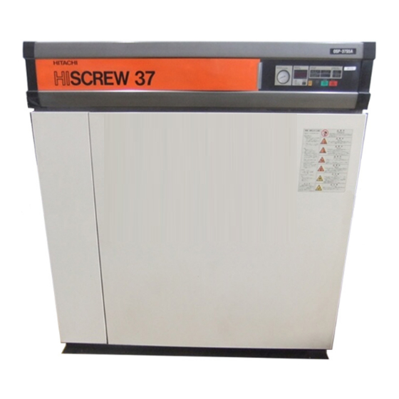
A nameplate is attached on the right enclosure panel. It indicates the A type (model number), motor out- put and frequency, working pressure, and manufacturing number. Inform the Hitachi distributor of such information whenever asking it to service your A. -
Page 7: Main Component Units
2. PARTS DESCRIPTION AND THEIR FUNCTIONS [Main Component Units and their Functions] 2.2 Main Component Units and their Functions Air Dryer Cooling Fan Cooling Fan Motor Air Intake Filter This removes the mois- Squirrel cage fan is used Totally enclosed 4-pole This prevents foreign ture in the compressed for cooling. -
Page 8: How To Operate
3. HOW TO OPERATE 3.1 Air Compressor Instrumentation Buttons/Lights for Operation Digital Monitor Discharge Air Pressure Gauge Running Mode Lights indicates the pressure of discharge air. The screen displays the running hours, The LOAD, REMOTE, discharge air temperatures, loading data, ECOMODE, and AUTO and shutdown/alarm codes. - Page 9 (2) Before shipping the models with a SELECT DRYER ECOMODE function that temporarily reduces the built-in air dryer, Hitachi presets its op- cutout pressures. The ECOMODE light becomes eration mode to automatic. If you want on (non-flashing and flashing) when this function is to enable manual operation mode, respectively enabled and activated.
-
Page 10: How To Use The Digital Monitor
3. HOW TO OPERATE [How to Use Digital Monitor and its Controls] 3.2 How to Use the Digital Monitor and its Controls (1) Displaying the Operating Hours, Pressure, Discharge Air Temperature, Loading Rate, Total Loading Time, and Alarm or Shutdown Code Dot: Indicates updating of the operating hours. - Page 11 1. Do not change the reference time for shifting to IMPORTANT ECOMODE control. See page 31. Hitachi presets the standard cutoff pressure to the cor- 2. To enable the alternative cutoff/cutin pressure func- responding specification pressure. Always set the cut-...
-
Page 12: Initial Start-Up
3. HOW TO OPERATE [Initial Start-Up] 3.3 Initial Start-Up IMPORTANT CAUTION Every button such as START, STOP and RESET will Before turn the power ON, make sure if not function unless the switch held down more than 0.3 zinstallation, xpiping and celectrical wir- second. - Page 13 3. HOW TO OPERATE [Initial Start-Up] 3.3.3 Operation q Press the START button. ⑤ ①② w START light glows and the compressor starts. e Gradually closing the discharge side valve, and keep running-in of the machine at the dis- charge pressure of 0.49-0.59 MPa for an hour. ⑥...
-
Page 14: Setting Of The Control Functions
3. HOW TO OPERATE [Setting of the Control Functions] 3.4 Setting of the Control Functions 3.4.1 Setting of Capacity Control Mode Power As listed in the table below: Supply ⑥ ・ The S- and M-type As provide two ca- ①⑤ pacity control modes each. - Page 15 3. HOW TO OPERATE [Setting of the Control Functions] ( 2) ⑦ ( 3) ⑧⑨ 3.4.3 Enabling the Remote Operation Action of Remote Operation RUNNING MODE REMOTE Light The following 3 methods (1), (2), and (3) are avail- Method (1): 遠 方...
- Page 16 3. HOW TO OPERATE [Setting of the Control Functions] 3.4.4 Setting of Air Dryer This page describes for the models with a (1) Operation Modes built-in air dryer. As listed in the table left, the models with a built-in Without air dryer provide 3 operation modes.
-
Page 17: Daily Operation
SHUTDOWN of the compressor. Investigate the cause and take necessary measures when the Relief Valve functions or the compres- sor stops by other safety device. Ask your dealer or your nearest Hitachi Service Station if there is any question. - Page 18 3. HOW TO OPERATE [Daily Operation] 3.5.3 Operation q Press the START button. ④ ① Make sure that the air compressor starts. ・ For the air dryer prestarting ( p. 14) disabled: Make sure that the built-in air dryer starts simultaneously.
-
Page 19: Daily Check
Take this In case of multiple unit operation, it is rec- plug out. ommended to attach an oil cleaner to the unit. Ask your dealer or Hitachi’s service station for this information. Do not open the oil-draining valve when Saucer the A is operating. -
Page 20: Lubricant Management
Lower level line IMPORTANT Ask your dealer or Hitachi’s service station for replace- OSP-22SA ( R ) I OSP-37SA ( R ) I Type ment of the genuine synthetic oil (NEW A OIL 2000). - Page 21 4. DAILY CHECK [Lubricant Management] 4.3.2 How to change oil q Press the STOP button. w Disconnect the power. e Be sure that the pressure in the compressor is decreased to the ambient pressure level (Check if the Pressure Gauge indicates 0 MPa). r Detach the door and the right enclosure panel.
-
Page 22: Troubleshooting
In case where ALARM is given or a SHUTDOWN happens, remove its causes before restart the unit. Ask your dealer or your nearest Hitachi Service Station if you have any question or unclear point. 5.1 When ALARM or SHUTDOWN is Displayed 5.1.1 ALARM Light Flashing... -
Page 23: Override Operation
Sometimes this may solve the problem. If the problem persists or the shutdown code is still displayed, proceed to enable an over- ride operation. CAUTION While you proceed to an override operation, contact your Hitachi distributor to fix the A as early as possible. - Page 24 5. TROUBLESHOOTING [Override Operation] 5.2.1 Enabling Override Operation q Press the RESET button. Power w Disconnect the power. Supply ① ②⑥ e Detach the door (for the 22 kW models) or the front enclosure panel (for the 37 kW models), and remove the starter cover.
-
Page 25: Shutdown/Alarm Indications
ALARM or SHUTDOWN (as ‘A/S’ below) code. If this is the case, refer to the following table to identify the cause. If you cannot identify the cause, or for the problem with a mark in the table, contact a Hitachi distributor. Light:... - Page 26 5. TROUBLESHOOTING [SHUTDOWN/ALARM Indications on the Instrument Panel] Light: Category of What and How How to Causes What Actions to Take Mark Code Action Problem Shutdown to Detect Reset History Failed or discon- E-31 SHUTDOWN: Failure or Disconnect the power and check the TH1. Operating Automatically On (flashing)
- Page 27 In addition, it covers the floor because it is larger in specific weight than the air, which may cause oxygen deficit to the personnel. When the Freon gas leaks, therefore, extinguish the fire, ventilate the room with a sweep-the-floor motion, and contact a Hitachi distributor.
-
Page 28: A List Of Shutdowns Not Displayed On Instrument Panel
5. TROUBLESHOOTING [A List of SHUTDOWNS Not Displayed on Instrument Panel] 5.4 A List of SHUTDOWNS Not Displayed on Instrument Panel Ask your dealer or Hitachi’s Service Station if the cause of malfunction is unknown or with mark shown in a REMARKS column. - Page 29 2. Do not operate the unit without protective equipment. In case of SHUTDOWN, read this section “5. TROUBLESHOOTING” to remove the cause. If the cause is unknown, inform and ask your dealer or Hitachi Service Station. CAUTION Running the unit with its loose belt brings not only lowered discharge air capacity due to its slipping, but also life of belt shortened.
-
Page 30: System Of Each Component
6. SYSTEM OF EACH COMPONENT 6.1 Compressed Air/Lubricant System Air Exhausted from Air Dryer Air Exhausted from Air Compressor Cooling Fan Cooling Fan Air Sucked onto Air Dryer Refrigerant Fan Motor Compressor Air Cooler Compressed Air Discharged Condensate Drained 6 3SV Oil Separator Air Sucked into Air End Unloader Minimum Pressure/ Relief Check Valve Valve Air Intake Filter Compressor TH1... -
Page 31: Capacity Control System
6. SYSTEM OF EACH COMPONENT [Capacity Control System] 6.2. Capacity Control System Operation air flow Only for the 22 kW models At start : 20P (NO-COM) Suction throttle 20US (NC-COM) valve closed. Only for the 37 kW models Modulator valve Load : 20P (NC-COM) Suction throttle 20US (NO-COM) valve open. Orifice U-type: Pressure Suction throttle 20US... - Page 32 6. SYSTEM OF EACH COMPONENT [Capacity Control System] 6.2.2 I-Type Capacity Control Pressure t=1 Cycle Time (Standard setting for S-type at delivery 0.69 MPa from the factory) 0.59 MPa This controls the capacity as a flow chart in the Time right figure. t<28 seconds t≥28 seconds Cycle Time: t...
- Page 33 This is not abnormal. 6.2.5 ECOMODE Function ECOMODE function is a standard feature of the S- and M-type A. It is disabled, however, by Hitachi before shipping the A. 運転管理 RUNNING CONTROL エコモード 警報...
- Page 34 If you want to use this function, contact your LOAD Light ON (non-flashing) ON (flashing) when loading Hitachi distributor to modify the control circuit, External ON/OFF Switch install an external on/off switch, and set the cutoff and cutin pressures to as required. Time To activate this function, turn on the external on/ off switch.
-
Page 35: Dryer System
6. SYSTEM OF EACH COMPONENT [Dryer System] 6.3 Dryer System Compressed air inlet Compressed air :Air flow outlet :Ventilation Precooler A :Refrigerant flow Heat exchanger Refrigerant pressure gauge (low-pressure side) Air cooler B Accumulator I Auto drain trap C High-pressure switch Hot gas bypass valve G Capillary tube Fan control Condenser E switch Refrigerating compressor 6.3.1 Compressed Air Flow 6.3.2 Refrigerant Flow Compressed air precooled by the aftercooler is The high-temperature and high-pressure refrig- heat-exchanged with low-temperature com-... -
Page 36: Instructions For Installation
7. INSTRUCTIONS FOR INSTALLATION 7.1 Verification of Components Machine Standard Nameplate Check Accesstory Output (kW) Foundation Bracket, Foundation Bolts (M12, M16) 2 sets Fork Slot Covers 4 pieces Model M6 Bolts 8 pieces Frequency (Hz) Condensate Trap (only for the models with a built-in air dryer) 1 set 7.2 Instructions When Conveying Fork Lift... -
Page 37: Instructions When Installing
7. INSTRUCTIONS FOR INSTALLATION [Instructions When Installing] 7.3 Instructions When Installing WARNING 1. Never put anything inflammable (inflammable solvent etc.) near the Compressor, or such material may be compressed by the unit and brought explosion. 2. Never allow the operation which uses fire near the compressor. Sparks may get in the unit and damage inside. -
Page 38: Instructions When Piping
7. INSTRUCTIONS FOR INSTALLATION [Instructions When Piping] 7.4 Instructions When Piping 7.4.1. Air Receiver 7.4.3 Parallel operation When your plant airline has the volume of more (1) At one-unit is in operation, completely close than 40 liters, you can operate the A with- the stop valve to the discharge pipe on the out an air receiver tank. -
Page 39: Compressor Room Ventilation
7. INSTRUCTIONS FOR INSTALLATION [Compressor Room Ventilation] 7.5. Compressor Room Ventilation (1) The air-cooled type compressor will release in- Ventilation data ternal heat discharged as hot exhaust wind. Model OSP-22SA ( R ) I OSP-37SA ( R ) I Be careful for ventilation of the room. The OSP-22MA ( R ) I OSP-37MA ( R ) I Item... -
Page 40: Instructions On Electrical Wiring
A voltage drop compressor. If earth leakage circuit breaker will also occur during operation, which deenergizes other than Hitachi brand is used, ask your dealer the control circuit and shut the air compressor down. because its specific condition is different. - Page 41 7. INSTRUCTIONS FOR INSTALLATION [Instructions on Electrical Wiring] 7.6.3 Connecting the POWER 7.6.5 In case of Remote Operation Take the starter cover off and connect wires as In case the compressor is controlled for its start the following figure. and stop by the remote operation, it is required to Supply connect must not be obstructive to the dis- connect signal lines from remote place to the ter- assembling work of the enclosure.
- Page 42 7. INSTRUCTIONS FOR INSTALLATION [Instructions on Electrical Wiring] 7.6.7 Standard voltage wiring diagram (200/220 V) Digital Monitor RUNNING MODE Light (Earth leakage breaker) RESET ECOMODE 22kW EXK225 200A or EX225K 175A 3φ 200mA button button POWER START STOP AC200V 50Hz 37kW EX400B 225A or EX225K 225A light SELECT DRYER AC200V 60Hz Type of ELB shown is the case of 200 V. button button PWB2...
- Page 43 7. INSTRUCTIONS FOR INSTALLATION [Instructions on Electrical Wiring] Standard Factory Settings Flat Cable A Type S Type M Type No. 1 to 8 Air Dryer Alarming/Prestarting No. 1 & 2 Air Dryer Operation Mode ON, OFF ON, OFF (OFF, OFF) (OFF, OFF) No. 3 & 4 Capacity Control Mode ON, ON ON, OFF...
- Page 44 7. INSTRUCTIONS FOR INSTALLATION [Instructions on Electrical Wiring] 7.6.8 Differential voltage wiring diagram (380/400/415/440 V) Digital Monitor (Earth leakage breaker) RUNNING MODE Light 22kW EX100B 100A or EX100BK 75A 200mA RESET ECOMODE 37kW EXK225 150A or EX225K 125A button button POWER START STOP Type of ELB shown is the case of 380-440 V. 3φ...
- Page 45 7. INSTRUCTIONS FOR INSTALLATION [Instructions on Electrical Wiring] Standard Factory Settings Flat Cable A Type S Type M Type No. 1 to 8 Air Dryer Alarming/Prestarting No. 1 & 2 Air Dryer Operation Mode ON, OFF ON, OFF (OFF, OFF) (OFF, OFF) No. 3 & 4 Capacity Control Mode ON, ON ON, OFF...
-
Page 46: Periodic Maintenance
(1) ○ mark on the maintenance standard chart at pages 45 through 46 means an item which the user can carry out. (2) ● mark means that you ask your dealer or Hitachi’s Service Station to do. (3) Except for the case as specifically stated otherwise, maintenance time means consecutive maintenance schedule, e.g., once every year stands for another maintenance for the next year, and after next year, and so forth. -
Page 47: Maintenance Standards (A)
8. PERIODIC MAINTENANCE [Maintenance Standards (A)] 8.2 Maintenance Standards (A) · · · In case of annual run hour less than 6,000 hours The maintenance items marked with must be carried out by users or, optionally, may be ordered to the dealer. ○... -
Page 48: Maintenance Standards (B)
8. PERIODIC MAINTENANCE [Maintenance Standards (B)] 8.3 Maintenance Standards (B) · · · In case of annual run hour less than 3,000 hours The maintenance items marked with must be carried out by users or, optionally, may be ordered to the dealer. ○... -
Page 49: Auto Drain Trap For Dryer
8. PERIODIC MAINTENANCE [Auto Drain Trap for Dryer] 8.4 Auto Drain Trap for Dryer Check the drain discharge of auto drain trap ev- ery day. Periodically clean the auto drain trap according to the maintenance standards. Handle Pet cock the auto drain trap in the procedure given below. How to Disassemble/ A Body Clean the Auto Drain Trap... -
Page 50: Performance Check Of Relief Valve
In case where discharge pressure exceeds the range of the table below, or if the relief valve actuates, adjustment of the capacity control equipment is required. Ask your dealer or Hitachi Service Station. Specified 0.69 0.83 Discharge Pressure Full-Close 0.76 to 0.80 0.87 to 0.90... -
Page 51: Replacement Of Oil Filter Element
8. PERIODIC MAINTENANCE [Oil Filter Element] 8.7 Replacement of Oil Filter Element q Press the STOP button. w Turn the POWER OFF. e Close the Stop Valve on the discharge side. Head r Wait for the inner pressure of the compressor Oil Filter Element depressurized to the level of ambient air. -
Page 52: Cleaning And Replacement Of Air Intake Filter Element
8. PERIODIC MAINTENANCE [Air Intake Filter Element] 8.8 Cleaning and Replacement of Air Intake Filter Element q Press the STOP button. Clean or replace the air intake filter element, as soon as possible, if the error code of an element w Turn the POWER OFF. -
Page 53: Cleaning Of Cooler
20 to 40 mm from its end. IMPORTANT If the unit is heavily contaminated, more heavy duty cleaning such as steam cleaning seems to be required. Ask your dealer or Hitachi Service Station for informa- tion. Cleaning Cover Figure B: Rear View of 37 kW Models... -
Page 54: Inspection And Replacement Of
CAUTION Check Valve Body Control pressure adjustment must be car- ried out while the unit is in operation. Therefore, ask your dealer or Hitachi ser- vice station for the work. 8.10.2 Replacement of Minimum Pressure / Check Valve q Press the STOP button. -
Page 55: Replacement Of Oil Separator Element
8. PERIODIC MAINTENANCE [Oil Separator Element] 8.11 Replacement of Oil Separator Element 8.11.1 Remove the Oil Separator Element Use a special tool (genuine part No. 52303330) for removing a housing. Oil Separator Housing q Press the STOP button. Special Tool w Turn the POWER OFF. - Page 56 8. PERIODIC MAINTENANCE [Oil Separator Element] 8.11.2 Attach Oil Separator Element Housing When to change the element, change housing and square ring with new replacements as well. q Check if there is any damage found on the thread portion of the element head or the ditch Element portion of square ring seal.
-
Page 57: Inspection Of Belt
0.84 ues is obvious, tension adjustment is needed. (6 to 10) (90 to 150) MA ( R ) I Ask your dealer or Hitachi service station for 0.92 the adjustment. e It is possible to use a special tension meter to 0.69 measure tension of the belt directly. Ask your OSP-37 49 to 78.4... -
Page 58: When It Is Not Used For Long Time
○ deterioration or rusting. rusting. (NOTE) Ask your dealer or Hitachi Service Station for information. CAUTION The compressor air end (screw block) can have rustings if no anti-rusting measure (Measures before storing, sealing) are done to it. If the unit is restarted, this may result breakage in Locks or Bearings of the compressor. -
Page 59: Parts List
10. PARTS LIST Compressor Air End (22kW) ITEM DESCRIPTION Compressor Air End Assembly Male Rotor Female Rotor 50 Roller Bearings 25 Roller Bearings 20 Angular Ball Bearings 40 Angular Ball Bearings Casing D-Casing Spacer, 50 roller bearing S-Cover 40 Mechanical Seal S-Cover Packing D-Cover D-Cover Packing... - Page 60 10. PARTS LIST Motor Pulley ITEM DESCRIPTION Motor M-Sheave Motor Base Belt V-Pulley V-Pulley Washer V-Pulley Bolt Plate (1), motor-fixing Vibration Suppression Rubber Vibration Suppression Rubber Motor Guide Belt Adjusting Bolt Plate (2), motor-fixing Retainer, motor base Cooling Fan ITEM DESCRIPTION For the 37 kW Models Bell-Mouse...
- Page 61 10. PARTS LIST Suction Throttle Valve ITEM DESCRIPTION Suction Throttle Valve Assembly Unloader Case Unloader Cover Cap Seal Piston Unloader Spring Unloader Cover Packing Unloader Bush Metal Unloader Body Packing Unloader Cover Suction Pipe Unloader O-ring Suction Packing Nipple for Pressure Differential Sensor Pressure Differential Sensor Air Intake Filter Element Band...
- Page 62 10. PARTS LIST Oil Case & Oil Separator ※330 ITEM DESCRIPTION ※332 Oil Case Oil Separator Square Ring Relief Valve Bolt M12 Seal Washer Replenish Port O-ring Replenish Port Plug Thermister Oil Level Gauge Assembly Lubricant ‘NEW A OIL 2000’ (4 liters) ※...
- Page 63 10. PARTS LIST 667 (22kW) Discharge Air Piping 666 (37kW) [Models without a built-in air dryer] ITEM DESCRIPTION O-ring Discharge Pipe (2) Discharge Pipe (1) Joint, straight Joint, elbow O-ring [Models with a built-in air dryer] 667 (22kW) ITEM DESCRIPTION 666 (37kW)...
- Page 64 10. PARTS LIST Control Piping ITEM DESCRIPTION Solenoid valve (20P) For the 22 kW Models Pressure gauge Pressure gauge piping Modulator Valve Fixed onto the starter. Pressure sensor 3.5 Orifice Adaptor Vacuum relief valve Solenoid Valve (20US) Pressure switch For the 37 kW Models Connected to the ‘A’ section. Fixed onto the starter. A...
- Page 65 10. PARTS LIST Air Intake Duct & Air Exhaust Duct [Models without a built-in air dryer] For the 22 kW Models ITEM DESCRIPTION Casing, cooling fan Air Exhaust Duct Base, cooling fan motor Air Exhaust Duct Assembly Air Intake Duct, air dryer Cooler Duct (1) Cooler Duct (2) Cooler Duct (3) Inspection Cover...
- Page 66 10. PARTS LIST Enclosure [Models without a built-in air dryer] ITEM DESCRIPTION Rubber Bush 752 ( only for the 37 kW models) Rubber Bush Door Magnet Front Cover Instrumental Panel Chain Right Side Cover Power Cover Top Cover Rear Cover (1) Left Side Cover Noise Proofing Plate Common Base Side Cap Rear Cover (2)
- Page 67 10. PARTS LIST Instrumental Panel ITEM DESCRIPTION Instrumental Panel Seat Operation Printed Circuit Board Printed Circuit Board Cover Instrumental Panel Side Cap Starter Panel (200 V class) ITEM DESCRIPTION Starter Panel Assembly Electromagnetic Contactor 52 424(For the S-type models) Glass Tube Fuse 425(For the M-type models) Electromagnetic Contactor 42 Electromagnetic Contactor 6 Electromagnetic Contactor 88F...
- Page 68 10. PARTS LIST Starter Panel (400 V class) ITEM DESCRIPTION Starter Panel Assembly 424(For the S-type models) Electromagnetic Contactor 52 425(For the M-type models) Glass Tube Fuse Reversal Phase Transformer Huse Electromagnetic Contactor 42 Electromagnetic Contactor 6 Electromagnetic Contactor 88F Terminal Board Terminal Board Copper Plate Assembly Rubber Bush CPU Printed Circuit Board (for S-type) CPU Printed Circuit Board (for M-type)
-
Page 69: Operation Record Logbook
11. OPERATION RECORD LOGBOOK Refrigerant Suction Air Discharge Remarks Operation Hour Integral Pressure Discharge Temperature Temperature Lubricant Operating °C °C Date Pressure Replenishment Hours Parts Replacement, Other matters liter Start Stop Control Range Control Range Control Range and To be Recorded 0 to 40 0.41 to 0.73 100 or below... - Page 70 This page is intentionally blank.
-
Page 71: Standard Specification
12. STANDARD SPECIFICATION Compressor Specification OSP-22S5A ( R ) I / S6A ( R ) I OSP-37S5A ( R ) I / S6A ( R ) I Item Unit OSP-22M5A ( R ) I / M6A ( R ) I OSP-37M5A ( R ) I / M6A ( R ) I Operating gas Suction pressure... - Page 72 Note down your Compressor’s Specifications for reference in the future. Model OSP- Compressor Serial No. Installed on month year Start-Up on month year Purchased from Phone: Sales Person: HIA-542 2002.1 Printed in Japan ( S)...