
Related Manuals for CyberPower OLS6000E


Summary of Contents for CyberPower OLS6000E
- Page 1 Userˊs Manual OLS6000E(XL) OLS10000E(XL) CyberPower Systems Inc. www.cyberpower.com K01-C000044-06...
-
Page 2: Table Of Contents
CONTENT: 1. Safety .........................1 1.1. Installation ....................1 1.2. Operation ....................1 1.3. Maintenance, Servicing and Faults .............2 1.4. Transport ....................3 1.5. Storage .......................3 1.6. Standards ....................3 2. Description of Commonly Used Symbols ............4 3. Introduction .......................4 3.1. Feature .......................5 3.2. Electrical Specifications ................6 3.3. - Page 3 9.2. Dry contact Interface(optional) ..............31 9.3. RS232 Interface ..................31 9.4. Intelligent slot .................... 31...
-
Page 4: Safety
1. Safety Please read carefully the following user manual and the safety instructions before installing the unit or using the unit! 1.1. Installation This is permanently connected equipment, and it must be installed by qualified maintenance personnel. Condensation may occur if the UPS is moved directly from a cold to a warm environment. -
Page 5: Maintenance, Servicing And Faults
not connected to the building wiring terminal, for there is internal current source (batteries). In order to fully disconnect the UPS, first turn the input breaker in the "OFF" position, then disconnect the mains lead. Indiscriminate operation of switches may cause output loss or damage to equipment. -
Page 6: Transport
1.4. Transport Please transport the UPS only in the original packaging to protect against shock and impact. 1.5. Storage The UPS must be stockpiled in the room where is ventilated and dry. 1.6. Standards * Safety IEC/EN 62040-1 * EMI Conducted Emission........:IEC/EN 62040-2 Category C3 Radiated Emission........:IEC/EN 62040-2... -
Page 7: Description Of Commonly Used Symbols
2. Description of Commonly Used Symbols Some or all of the following symbols may be used in this manual. It is advisable to familiarize yourself with them and understand their meaning: Symbol and Explanation Symbol Explanation Symbol Explanation Alert you to pay Caution of high special attention voltage... -
Page 8: Feature
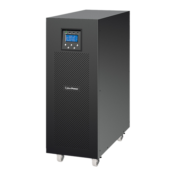
" XL" Model: Extended backup time. OLS6000E(XL) OLS10000E(XL) Fig.3-1 The rear view of OLS6000E(XL)/OLS10000E(XL) 3.1. Feature This series UPS is a new generation of UPS, which provides the outstanding reliability, and most cost-performance ratio in the industrial. Following benefit the product has: ... -
Page 9: Electrical Specifications
UPS is up to 4. ECO mode with high efficiency ≥96%, save power expense for user. Start-able without battery. 3.2. Electrical Specifications Input Model NO. OLS6000E(XL) OLS10000E(XL) Phase Single Voltage Range 110~276Vac(Depends on load level) Frequency Range (45~55)/(54~66)Hz... -
Page 10: Operating Environment
Storage temperature <95% <1000m 0℃~40℃ -15℃~50℃ Note: The load capacity should be derated 1% every 100m heightened on the basis of 1000m. 3.4. Dimensions and Weights Model NO. Dimensions W×H×D(mm) Net Weight (kg) OlS6000E 260×708×550 OLS6000EXL 260×708×550 OLS10000E 260×708×550 OLS10000EXL 260×708×550... -
Page 11: Installation
*PowerPanel® Business Edition software is available on our website. Please visit www.cyberpower.com and go to the Software Section for free download. CAUTION! Inspect the appearance of the UPS to see if there is any damage during transportation. Do not turn on the unit and notify the carrier and dealer immediately if there is any damage or lacking of some parts. - Page 12 4.2.2. Installation Use cable cross section and protective device specification : Model OLS6000E(XL) OLS10000E(XL) Protective earthing conductor 6mm² 10 mm² Min cross section (UL1015 10AWG) (UL1015 8AWG) Input L, N 6mm² 10 mm² Min conductor cross section (UL1015 10AWG) (UL1015 8AWG)
- Page 13 Open the terminal block cover located on the rear panel of UPS, please refer to the appearance diagram. For OLS6000E(XL), it is recommended to select the UL1015 10AWG (6mm² ) or other insulated wire which complies with AWG Standard for the UPS input and output wirings.
-
Page 14: External Battery Pack Connecting Procedure
"same voltage, same type" should be strictly followed. 2. For OLS6000E(XL), select the UL1015 10AWG (6mm² ) respectively or other insulated wire which complies with AWG Standard for the UPS battery wirings. -
Page 15: Epo Connection
Otherwise it may encounter the hazardous of electric shock. 1) Ensure the UPS is not powered on and the mains input breaker is set in the "OFF" position. 2) A DC breaker must be installed between the external battery pack and the UPS. -
Page 16: Operation
5. Operation 5.1. Display Panel The UPS has a five-button, dot matrix LCD with white text and a blue background. Besides the LCD, the UPS has four colorized LED to provide more convenient information. Fig.5-1 LCD Panel Control button functions :... - Page 17 LED definition: NORMAL BATTERY BYPASS FAULT UPS state (Green LED) (Yellow LED) (Yellow LED) (Red LED) Bypass mode with no □ ★ output Bypass mode with □ 〇 output □ 〇 Line mode □ 〇 〇 Battery mode □ 〇 〇...
-
Page 18: Turning On And Turning Off Ups
Check all the connection is correct. Check the breaker of external battery pack is in "ON" position. By pressing button continuously for more than 200ms, the UPS would be powered on. At this time the fan begins to rotate, LCD will show "CyberPower". -
Page 19: Lcd Operation
Then LCD will show the default UPS status summary screen after UPS finishing self-test. By pressing button continuously for more than 1 second,the buzzer will beep for 1s, UPS starts to turn on. A few seconds later, the UPS turns into Battery mode. If the mains power comes back, the UPS will transfer to Line mode without output interruption of the UPS. - Page 20 Alarm 0002:12:20:00 Cyberpower Line site 2/10 Up>200mS Down>200mS Up>200mS Down>200mS Alarm Alarm Enter>200mS 0002:12:00:00 0002:12:00:00 Overload Overload Control ESC>200mS ESC>200mS 1/10 1/10 Setting Events ESC>200mS Fault Fault Enter>200mS 0003:12:00:00 0003:12:00:00 Over tempearture Over tempearture ESC>200mS Down>200mS Up>200mS Up>200mS Down>200mS Load: 60 % Cable loss I/P Volt: 223.5 V...
- Page 21 Buzzer mute Clr EPO status Buzzer mute Clr EPO status Battery test Battery test Single UPS off Single UPS off Please input Password Sub setting... **** Event 0001:12:00:00 Utility abnormal 1/10 Alarm Control 0002:12:00:00 Setting Overload Events 1/10 Fault 0003:12:00:00 Over tempearture Clear all events Events&alarms...
- Page 22 The status screen : In the UPS status screen, when pressing >200ms the detailed information about UPS information that include alarm, fault output, input, bypass, load and battery parameter would be shown. See Fig.5-2. when pressing > 200ms the main menu would be shown. In fault or alarm screen, when pressing >...
- Page 23 Ambient temperature warning enabled/disabled enabled DC start enabled/disabled enabled Auto Restart enabled/disabled enabled Automatic overload restart enabled/disabled enabled Auto Bypass enabled/disabled enabled Short circuit clearance enabled/disabled disabled Power strategy** normal/ECO/converter normal Rated output voltage 208/220/230/240V 230V Output frequency 50/60Hz 50Hz Bypass voltage low range 10%,15%,20% Bypass voltage high range...
-
Page 24: Special Function
6. Special Function The series UPS has some special functions, which could satisfy some special application of user. And the functions have own features, please contact your local distributor for further information before using the function. 6.1. ECO Function Brief introduction of ECO function :... -
Page 25: Parallel Function
power strategy setting menu by following chapter of 5.3. 6.3. Parallel Function Brief introduction of the redundancy : N+X is currently the most reliable power supply structure. N represents the minimum UPS number that the total load needs, X represents the redundant UPS number, i.e. - Page 26 Disconnect the Jumper on J1 to J2 of the terminal block first, and connect each output breaker to a main output breaker and then to the loads. Each UPS needs an independent battery pack. Please refer to the wiring diagram in the following diagram. INPUT BATTERY JUMPER...
- Page 27 TO UTILITY Main Maintenance Bypass Switch Main Input Breaker Main Output Breaker TO LOAD Fig.6-3 Parallel installation diagram The distance between the UPS in parallel and the breaker panel is required to be less than 20 meters. The difference between the wires of input and output of the UPS is required to be less than 20%.
- Page 28 than 0.5V. If the difference is more than 0.5V, the UPS need to be regulated. 11) Press the button of one UPS, each UPS would start to turn off and transfer to the Bypass mode, switch on the output breaker of each UPS to parallel all the output of UPS together.
-
Page 29: Trouble Shooting
Set the main maintenance bypass switch from "UPS" to "BPS", switch off the main output breaker and the main input breaker, the UPS would shut down. Ensure the UPS shut down totally, remove the wanted UPS and reinstall the new UPS parallel system by following step 1) to 9) of the last chapter- "How to install a new parallel UPS system". - Page 30 The ground wire is disconnected, or phase Check Ground wire status; Site fail and neutral conductor Reverse mains power wiring at input of UPS system are reversed When audible alarm sounding every Battery volt low Battery voltage is low second, battery is almost empty Battery voltage is Bat over voltage higher than normal...
-
Page 31: Trouble Shooting According To Fault Indication
The UPS with different power There are different strategy setting (Ex. one Line mode Work Mode differ power strategy setting and one Converter mode) are in parallel system forbidden to parallel There are different Setting differ setting in parallel Check the setting. system ECO function is ECO function is forbidden in parallel... -
Page 32: Trouble Shooting In Else Cases
DC short Bus short Consult dealer DC Over Bus Over Voltage Consult dealer DC Under Bus Under Voltage Consult dealer DC Unbalance Bus Unbalance Consult dealer DC soft fail Bus Soft start fail Consult dealer Output soft fail Output Soft start fail Consult dealer Output Volt low Output Volt low... -
Page 33: Battery Maintenance
Date on which the problem occurred. LCD/LED display information, Buzzer alarm status. Mains power condition, load type and capacity, environment temperature, ventilation condition. The information (battery capacity, quantity) of external battery pack if the UPS is "XL" model. Other information for complete description of the problem. 8. -
Page 34: Communication Port
6F, No. 32, Sec. 1, Chenggong Rd., Nangang District, Taipei 115, Taiwan © Entire contents copyright 2013 CyberPower Systems Inc., All rights reserved. Reproduction in whole or ® ® in part without permission is prohibited. PowerPanel Business Edition and PowerPanel Personal Edition are trademarks of CyberPower Systems Inc.