
Related Manuals for CyberPower OLS2000EC/XL


Summary of Contents for CyberPower OLS2000EC/XL
- Page 1 User’s Manual OLS1000EC/XL OLS2000EC/XL OLS3000EC/XL CyberPower Systems Inc. www.cyberpower.com K01-C000236-03...
-
Page 2: Important Safety Instructions
IMPORTANT SAFETY INSTRUCTIONS This manual contains important instructions. Please read and follow all instructions carefully during installation and operation of the unit. Read this manual thoroughly before attempting to unpack, install, or operate the UPS. CAUTION! The UPS must be connected to a grounded AC cause damage to your equipment and cause fire hazards. - Page 3 UNPACKIN Batte ry cable (for lo ong-run mode ls only) Input po ower cord Outpu ut power cord( (for IEC Mode els only) User’s manual RS232 2 communicat tion cable(Opt tional) Warran nty Card werPanel® Bu siness Edition n software is a available on ou www.cyb berpower.com...
-
Page 4: Installing Your Ups System
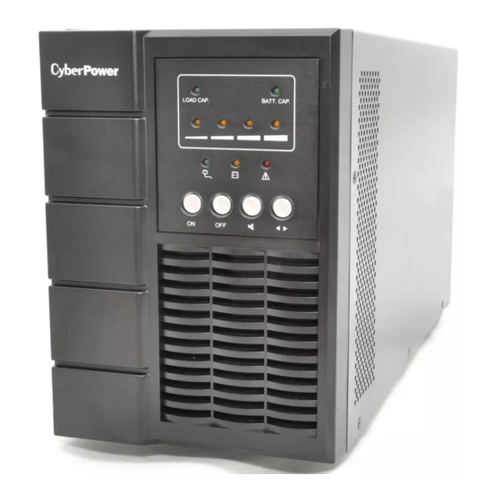
INSTALLING YOUR UPS SYSTEM SYSTEM BLOCK DIAGRAM HARDWARE INSTALLATION GUIDE Battery charge loss may occur during shipping and storage. UPS is plugged into an AC outlet, the battery will automatically Before using the UPS, it’s strongly recommended to charge charge, even when the unit is switched off. - Page 5 BASIC OPERATION POWER MODULE FRONT/REAR PANEL DESCRIPTION 1. Power On/Off Button 7. Serial Port Master ON/OFF for the UPS. Serial port provides communication between the UPS and the computer. The UPS can control the computer’s shutdown 2. Function Buttons during a power outage through the connection while the Scroll up, scroll down, and silence.
- Page 6 BASIC OPERATION OLS3000EC BATTERY MODULE FRONT/REAR PANEL DESCRIPTION 1. Input Connector Use this input connector to daisy chain the next Battery module. Remove the connector cover for access. 2. On-board Replaceable Fuse Cover Replaceable fuse is accessible from the rear panel.
- Page 7 BASIC OPERATION CONNECTION #1: Connect the input and output of UPS Step1: Plug UPS to a two-pole, three-wire, grounded receptacle only. Avoid using extension cords. Step2: For socket-type outputs, please connect devices to the outlets. Step3: For terminal-type outputs, please follow below steps: Remove the small cover of the terminal block Suggest using AWG16 power cord the connect UPS...
- Page 8 BASI IC OPERA ATION NNECTION # #2 : POWER R MODULE W WITH ONE B BATTERY M MODULE Step p 1: Using the grounded wire e and screw to o connect the battery cable and the groun Step p 2: Use the ba attery cable to o connect the U UPS.
- Page 9 BASIC OPERATION ...
- Page 10 BASIC OPERATION CONNECTION #3: POWER MODULE WITH MULTIPLE BATTERY MODULES Step1: Connect the 1 Battery module to the Power module using battery cable. Step2: Use the battery cable to connect the 2 Battery module to the 1 Battery module. ...
-
Page 11: Basic Operation
BASIC OPERATION CONNECTION #4: POWER MODULE WITH HIGH-CAPACITY BATTERIES Step1: Connect the Batteries in series according to the system DC voltage, such as 1000VA(24VDC),2000VA(48VDC),. 3000VA(72VDC). Step2: Follow battery polarity guide located near battery cables as below. “+” Red cable for battery positive polarity; “-”... -
Page 12: Operation Description
BASIC OPERATION BUTTON OPERATION Button Operation Description Press this button to turn on UPS. Press this button to turn off UPS. Press this button simultaneously for 5 seconds to disable or enable the alarm system while in battery mode. Press this button to select load level or battery capacity display function on LED panel. -
Page 13: Ups Status Display
BASIC OPERATION UPS Status Display LED Indicators Alarm Status Item 0-25%LOAD LEVEL ● ● No Warning 26-50%LOAD LEVEL ● ● ● No Warning 51-75%LOAD LEVEL ● ● ● ● No Warning 76-100%LOAD LEVEL ● ● ● ● ● No Warning 0-25%BAT CAP ●... -
Page 14: Maintenance
Only use replacement batteries which are Please refer to the front side of the UPS for the model certified by CyberPower Systems. Use of incorrect battery number of the correct replacement batteries. For battery type is an electrical hazard that could lead to explosion, fire, procurement, log onto www.cyberpower.com, or contact your... -
Page 15: Technical Specifications
TECHNICAL SPECIFICATIONS OLS3000ECa/ OLS1000EC/XL OLS2000EC/XL OLS3000EC Model Configuration Capacity (VA) 1000VA 2000VA 3000VA 3000VA Capacity (Watts) 800W 1600W 2400W 2400W Form Factor Tower Yes, ECO Mode Efficiency ≧95% Energy-saving Technology Input 110~300Vac ± 5% for 1000/2000/3000VA model @ 0~50% Load ± 5% 120~300Vac ±... - Page 16 TECHNICAL SPECIFICATIONS Software Power Management ® Software PowerPanel Business Edition Physical 5.51x7.50x12.87in 5.94 x8.86 x15.51in. 7.72 x13.28x16.38in 5.94 x 8.86x15.51in. Dimensions(W×H×D)mm (140x190.6x327mm) (151×225×394mm) (196×343×416 mm) (151×225x394 mm) 18.7/9.9lbs 31.1/15.7lbs 55.15lbs 41.0/17.6lbs Net Weight (8.5/4.5Kg) (14.1/7.1Kg) (25.01Kg) (18.6/8.0Kg) *) Within 50/60Hz±8% by default, the output frequency is synchronization with input mains. User can adjust the acceptable range for output frequency (±1, 2, 3, 4, 5, 6, 7, 8, 9, 10%).
-
Page 17: Troubleshooting
6F, No. 32, Sec. 1, Chenggong Rd., Nangang District, Taipei 115, Taiwan © Entire contents copyright 2017 CyberPower Systems Inc., All rights reserved. Reproduction in whole or in part without ® ® permission is prohibited. PowerPanel Business Edition and PowerPanel Personal Edition are trademarks of CyberPower Systems Inc.