Advertisement
Quick Links
READ AND SAVE THESE INSTRUCTIONS
®
Installation, Operation and Maintenance Manual
Upon receiving unit, check for any damage and report it immediately to the shipper. Also check to see that all accessory
items are accounted for.
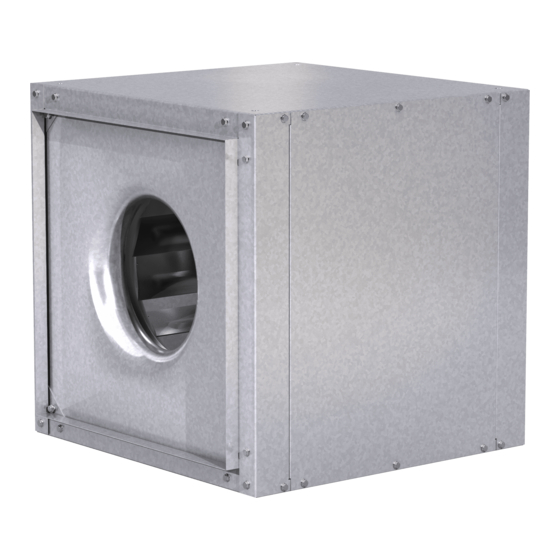
Move fan to desired location and determine position of access panels and motor. Attach the fan to a suitable framework
as specified (hanging or base vibration isolators are recommended). See chart below for dimensions of vibration isolator
centerlines (Fig. 1). See Fig. 2 and 3 for physical dimensions.
The motor's amperage and voltage ratings must be checked for compatibility to supply voltage prior to final electrical
connection. Supply wiring may be routed through knockouts which are provided on the top and bottom of each fan housing.
Provide adequate wiring to permit the access doors to open for servicing. Wiring should be secured inside the fan to prevent
interference with the drive components. All wiring must conform to local and national codes.
Inlet and discharge collars are provided for duct connection. The inlet panel is removable for attaching optional filter box
accessory.
VIBRATION ISOLATOR DIMENSIONAL DATA
Unit Size
A
80
20
3
/
4
90
21
3
/
4
100
23
3
/
4
120
30
1
/
2
150
32
180
37
3
/
8
200
47
3
/
8
M* applies to optional filter box only.
BDF DIMENSIONAL DATA
Fig. 2
BDF Unit
A
B
2
C
I
G
F
J
Unit
A
B
C
Size
80
23
/
18
/
15
/
15
1
1
7
4
2
8
90
24
1
/
21
1
/
18
3
/
4
4
4
100
26
1
/
22
3
/
20
3
/
4
4
4
120
33
27
1
/
22
3
/
4
4
150
34
3
/
32
5
/
27
3
/
4
8
4
180
40
1
/
41
3
/
31
3
/
4
4
4
200
50
1
/
49
1
/
39
3
/
4
4
4
K* is length of fan and filter box combined.
C
M*
22
11
/
26
5
/
16
16
25
5
/
30
1
/
8
2
27
1
/
25
2
/
8
5
31
5
/
30
7
/
8
16
35
27
/
1
8
44
34
15
/
16
51
1
/
36
2
D
E
H
D
E
F
G
/
12
/
9
/
8
/
3
11
3
7
16
16
4
8
18
1
/
15
7
/
12
1
/
10
1
/
4
8
4
2
19
3
/
17
7
/
13
3
/
11
7
/
4
8
4
8
24
1
/
19
7
/
16
13
3
/
8
8
8
28
5
/
23
7
/
19
1
/
16
3
/
1
8
8
8
8
37
1
/
27
7
/
22
1
/
18
7
/
1
2
8
2
8
45
1
/
36
23
1
/
25
1
/
1
8
8
4
Fig. 3
BDF w/ Filter Box
C
Filter
H
I
J
K*
Size
1
5
/
4
/
49
/
16 x 20
3
1
3
8
4
4
1
6
3
/
4
1
/
54
7
/
20 x 25
4
2
8
1
7
3
/
4
1
/
51
7
/
20 x 20
8
2
8
1
7
7
/
5
5
/
63
9
/
12 x 25
8
8
16
1
/
9
7
/
6
3
/
62
1
/
16 x 20
2
8
4
16
1
/
10
1
/
9
5
/
75
3
/
20 x 25
2
2
8
8
1
/
12
1
/
13
85
1
/
16 x 25
2
2
4
Model BDF
Belt Drive Duct Fan
M*
A
C
M*
A
C
K*
B
2
I
G
F
J
Number
Material
of Filters
Thickness (ga.)
2
20
2
20
2
20
4
20
8
20
6
20
12
20
PN 458341
Fig. 1
D
E
H
Approx. Wt. (lbs)
Fan
Filter Box
71
32
92
42
107
52
144
70
223
97
307
134
565
174
Advertisement

Related Manuals for Greenheck BDF


Summary of Contents for Greenheck BDF
- Page 1 VIBRATION ISOLATOR DIMENSIONAL DATA Unit Size M* applies to optional filter box only. Fig. 1 BDF DIMENSIONAL DATA Fig. 2 Fig. 3 BDF Unit BDF w/ Filter Box Approx. Wt. (lbs) Unit Filter Number Material Size Size of Filters Thickness (ga.)
- Page 2 (See Fig. 5) For all BDF units, belt tension can be adjusted by loosening four fasteners (marked “R”) on the drive frame. The motor plate slides on the slotted adjusting arms (see Fig. 6). Belt tension should be adjusted to allow 1/64” of deflection per inch of belt span.
-
Page 3: Troubleshooting
MAINTENANCE Belts tend to stretch after a period of time. They should be checked periodically for wear and tightness. When replacing belts, use the same type as supplied with the unit. Matched belts should always be used on units with multigroove pulleys. For belt replacement, loosen the tensioning device far enough to allow removal of the belt by hand. -
Page 4: Parts List
Warranty Greenheck warrants this equipment to be free from defects in material and workmanship for a period of one year from the purchase date. Any units or parts which prove to be defective during the warranty period will be replaced at our option when returned to our factory, transportation prepaid.