Table of Contents

Related Manuals for SOYO SY-5EH5


Summary of Contents for SOYO SY-5EH5
-
Page 1: Technical Reference
SY-5EHM/5EH5 V1.3 Super 7 Motherboard ************************************************ ® Pentium Class CPU supported ETEQ82C663 PCI/AGP Motherboard AT Form Factor ************************************************ User's Guide & Technical Reference... - Page 2 System Model Name Hardware Revision CPU Model On Board Memory/L2 Cache System BIOS Best regards, : SOYO COMPUTER INC. : SY-5EHM/5EH5 : N/A : Intel Pentium 200/66Mhz : PC100 SDRAM DIMM 32MBx1 /1MB : Award Modular BIOS V4.51PG, An Energy Star Ally Copyright ©...
-
Page 3: Declaration Of Conformity
The product was tested with the following configuration: Monitor: SONY/AK8GDM17SE2T Modem: ACEEX/IF AXDM1414 This declaration is given for the manufacturer SOYO COMPUTER INC. No.21, Wu-Kung 5 Rd., Hsing Chuang City, Taipei Hsien, Taiwan, R.O.C. The test was carried out by SPORTON INTERNATIONAL INC. -
Page 4: About This Guide
Our customers should ensure that their use of our products does not infringe upon any patents. It is the policy of Soyo Computer Inc. to respect the valid patent rights of third parties and not to infringe upon or assist others to infringe upon such rights. -
Page 5: Table Of Contents
Table of Contents Table of Contents SY-5EHM/5EH5 V1.3 MOTHERBOARD LAYOUT... 1 CHAPTER 1 INTRODUCTION... 2 KEY FEATURES ... 2 HANDLING THE MOTHERBOARD ... 5 ELECTROSTATIC DISCHARGE PRECAUTIONS ... 5 CHAPTER 2 HARDWARE SETUP ... 6 PREPARATIONS ... 6 UNPACKING THE MOTHERBOARD ... 7 INSTALLATION GUIDE ... -
Page 6: Sy-5Ehm/5Eh5 V1.3 Motherboard Layout
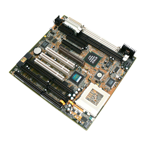
Motherboard Features SY-5EHM/5EH5 V1.3 Motherboard Layout Flash BIOS PCI Slot #3 ISA Slot #3 ISA Slot #2 ISA Slot #1 Power Keylock Turbo HDD LED SW2 JP1 JP12 SY-5EHM/5EH5 V1.3 Platform Lithium Battery FDC37C669Q JP44 AGP Slot PCI Slot #2 PCI Slot #1 ETEQ EQ82C6629... -
Page 7: Chapter 1 Introduction
Supports Rise mP6 PR-266 MHz speeds CPU Features Socket 7 for CPU easy upgrade Supports P54C/P55C series SIMM Mode and CPU Stop Clock L2 Cache Controller On-board 512KB(SY-5EH5 V1.3) or 1MB (SY-5EHM V1.3) Level 2 Pipeline Burst SRAM Cache DRAM Controller Chapter 1 INTRODUCTION SY-5EHM/5EH5 V1.3... - Page 8 Introduction Supports 2 strips of 168-pin SDRAM unbeffured DIMM 2 x 168-pin DIMM banks support 8/16/32/64/128/256 MB unbuffered DIMM modules Support 2 strips of 72-pin FPM/EDO SIMM 2 x 72-pin SIMM banks support 8/16/32/64 MB SIMM modules Memory configuration: System memory: 8MB to 640MB with EDO/SDRAM SY-5EHM/5EH5 V1.3 PLATFORM FEATURES Board Size 4-layer PCB, 22x23cm(8.7”x9.1”), AT Form Factor...
- Page 9 Introduction (Supports 1.2MB/1.44MB/2.88MB and LS120/3-mode FDD) 5-pin Serial Infrared Device Connector Keylock 5-pin KeyLock Connector Reset 2-pin Reset Switch Connector Speaker 4-pin PC Speaker Connector TB_LED 2-pin Turbo LED Connector HDD_LED 2-pin IDE Device LED Connector PWRBT ATX Power On/Off Switch 2-pin Connector Single or Dual voltage selection Jumper CMOS Clear Jumper CPU bus clock frequency Jumper...
-
Page 10: Handling The Motherboard
Introduction 1-2 HANDLING THE MOTHERBOARD To avoid damage to your Motherboard, follow these simple rules while unpacking: Before handling the Motherboard, ground yourself by grasping an unpainted portion of the system's metal chassis. Remove the Motherboard from its anti-static packaging. Hold the Motherboard by the edges and avoid touching its components. -
Page 11: Chapter 2 Hardware Setup
Hardware Setup HARDWARE SETUP Congratulations on your purchase of SY-5EHM/5EH5 V1.3 Super 7 Motherboard. You are about to install and connect your new Motherboard. Note: Do not unpack the Motherboard from its protective anti-static packaging until you have made the following preparations. -
Page 12: Unpacking The Motherboard
Hardware Setup 2-2 Unpacking the Motherboard When unpacking the Motherboard, check for the following items: The SY-5EHM/5EH5 V1.3 ETEQ82C663 PCI/AGP Motherboard The Quick Start Guide * The Installation CD-ROM * The CPU Retention Set One IDE Device Flat Cable One Floppy Disk Drive Flat Cable One bracket with one 9-pin serial connector, attached with 9-pin flat cable, and one 6-pin PS/2 mouse connector, attached with 6-pin cable. -
Page 13: Installation Guide
Hardware Setup SY-5EHM/5EH5 V1.3 2-3 Installation Guide We will now begin the installation of the Motherboard. Please follow the step-by-step procedure designed to lead you to a complete and correct installation. Step 1. CPU Installation ® Follow these instructions to install your Pentium class processor correctly. - Page 14 Hardware Setup Follow these steps to install the CPU in the Socket 7: Lift the socket handle up to a vertical position. Align the blunt edge of the CPU with the matching pin-hole distinctive edge on the socket. Seat the processor in the socket completely and without forcing.
- Page 15 Hardware Setup Step 3. CPU Voltage Setting (SW2,JP1) Single or Dual Voltage Selection CPU Voltage Please verify the correct voltage with your dealer before installation. Use the following tables to set SW2 to the proper "Voltage Value", according to the specifications marked on your CPU: This Motherboard comes with pre-configured setting of CPU voltage.
- Page 16 Hardware Setup CPU you are installing and adjust the settings on SW2 accordingly. This motherboard supports CPU core voltages from 2.0 to 3.5V in 0.1V increments. Use the following tables to set the CPU voltage jumpers SW2 to match the voltage value of your CPU: CPU Core Voltage Setting: SW2 Voltage Value 3.5V...
- Page 17 Hardware Setup Processor Voltage Setting Intel P54C - P100 Intel P54C - P133 Intel P54C - P166 Intel P54C - P200 Intel P55C - P166 Intel P55C - P200 Intel P55C - P233 AMD K5 - PR100 AMD K5 - PR133 AMD K5 - PR166 AMD K6 166 AMD K6 200...
- Page 18 Hardware Setup Voltage Settings for Various Processors (continued) Processor Voltage Setting AMD K6-2 450 AMD K6-2 475 AMD K6-2 500 AMD K6-III 400 AMD K6-III 450 The AMD K6-2 and K6-III come in several versions with different voltages. Please ask your dealer for the correct voltage. AMD K6-2 550 Cyrix 6x86(L) PR166+ Cyrix 6x86(L) PR200+...
- Page 19 Hardware Setup SY-5EHM/5EH5 V1.3 Step 4. CPU Frequency Setting (SW1) 1 2 3 4 5 6 Host Bus Frequency 1 2 3 4 5 6 Frequency Multiplier The SY-5EHM/5EH5 V1.3 Motherboard is designed to support most ® Pentium class processors currently on the market. Jumpers SW1 is used to configure the Motherboard frequency parameters to match the working frequency of your CPU.
- Page 20 Hardware Setup CPU FREQUENCY SETTING (SW1) Configure the SW1 jumpers to the settings that match your CPU speed. Refer to the following tables to set the Frequency Multiplier and Host Bus Frequency of your CPU: Frequency Multiplier Multiplier 1.5/3.5x 2.0x* 2.5x 3.0x 4.0x...
- Page 21 Hardware Setup Please refer to the following table that gives you the correct frequency settings for the specific brand and model of CPU you are installing on this Motherboard. Frequency Settings for Intel Processor Frequency Setting Intel P54C - P100 Intel P54C - P133 Intel P54C - P166 Intel P54C - P200...
- Page 22 Hardware Setup Frequency Settings for AMD™ Processors (Continued) Processor Ratio Frequency Setting AMD K5 - PR166 2.5 x 66MHz AMD K6 - 166 2.5 x 66MHz AMD K6 - 200 3.0 x 66MHz AMD K6 - 233 3.5 x 66MHz AMD K6 - 266 4.0 x 66MHz AMD K6 - 300...
- Page 23 Hardware Setup Frequency Settings for AMD™ Processors (Continued) Processor Ratio Frequency Setting AMD K6-2 380 4.0 x 95MHz AMD K6-2 400 4.0 x 100MHz AMD K6-2 450 4.5 x 100MHz AMD K6-2 475 5.0 x 95MHz AMD K6-2 500 5.0 x 100MHz AMD K6-2 533 5.5 x 97MHz AMD K6-2 550...
- Page 24 Hardware Setup Frequency Settings for Cyrix™ Processors Processor Frequency Setting Cyrix 6x86 - PR166+ Cyrix 6x86 - PR200+ Cyrix MX - PR166** Cyrix MX - PR200** Cyrix MX - PR200** Cyrix MX - PR233** Cyrix MX - PR266** Cyrix M II - 300** Cyrix M II - 300** Cyrix M II - 333** Cyrix M II - 333**...
- Page 25 Hardware Setup Frequency Settings for Cyrix™ Processors (Continued) Processor Frequency Setting Cyrix M II – 400** Cyrix M II - 433** Frequency Settings for IDT™ Processors Processor Frequency Setting IDT X86 CPU 2-233 IDT X86 CPU 2-266 IDT X86 CPU 2-300 Frequency Settings for Rise™...
- Page 26 Hardware Setup Step 5. Set JP7,JP9,JP10 for SDRAM frequency JP7 is used to indicate the frequency of the CPU bus clock to the ETEQ chipset. JP9 and JP10 are used to determine that the SDRAM is running at the frequency of the CPU bus clock or the AGP clock. CPU BUS AGP BUS Clock...
- Page 27 Hardware Setup Step 6. DRAM Module Installation This Motherboard supports two strips of 72-pin 5V FPM/EDO DRAM (SIMM) from 4 to 64 MB and two strips 168-pin 3.3V/5V Unbuffered DIMM modules from 8 to 256 MB. The Motherboard requires SIMM modules of at least 70ns access time. This Motherboard supports both EDO and SDRAM types of memory modules.
-
Page 28: Memory Configuration Table
Hardware Setup Your board comes with one SIMM Bank (2 modules) and two DIMM sockets, providing support for up to 512MB of main memory using DIMM modules from 8MB to 256MB. For 66MHz host bus CPUs use 12ns or faster DIMM modules; for 83MHz or higher host bus CPUs use 8ns modules. - Page 29 Hardware Setup Step 9. Front Panel Connections Power Keylock Turbo Plug the computer case's front panel devices to the corresponding connectors on the Motherboard. 1. Power LED & KeyLock Plug the Power LED cable into the 5-pin Keylock connector. Some systems may feature a KeyLock function with a front panel switch for enabling or disabling the keyboard.
- Page 30 Hardware Setup SY-5EHM/5EH5 V1.3 3. Speaker Attach the 4-pin PC speaker cable from the case to the Speaker connector on the Motherboard. 4. Turbo LED Connecting the 2-pin Turbo LED cable to the corresponding Turbo LED connector will cause the LED to light whenever the system is in Turbo mode.
- Page 31 Hardware Setup Step 10. External Peripherals Connections External devices such as the keyboard, printer, PS/2 mouse, modem, USB can be connected to the Motherboard. Normally, you can not plug your devices directly onto the Motherboard, except for the keyboard that plugs directly into the back panel KB connector. For other parallel (PRT1) and serial devices (COM1, COM2), first install the external connectors that come with your Motherboard on the computer case, then plug the other end of the flat cable to their...
- Page 32 Hardware Setup 1. Serial Ports COM1/COM2 External Devices that use the COM ports include serial mice and modems. The COM port connectors are located on 2 separate brackets panels, as shown on the figure below. Please plug their respective 10 pin flat cable connectors into the COM1 and COM 2 serial port connectors on the Motherboard.
- Page 33 Hardware Setup Parallel Port PRT1 This parallel port is used to connect the printer or other parallel devices. Your Motherboard comes with one 25-pin female external parallel connector with 25-pin flat cable. Plug the 25-pin end of the flat cable into the PRT1 parallel connector on the Motherboard, as shown in the figure below, then fix the bracket to one of the slots at the back of the computer case using a screw.
- Page 34 Hardware Setup PS/2 Mouse Attach the mouse cable to the 6-pin male PS/2 mouse connector on the Motherboard to enable PS/2 mouse function. Universal Serial Bus (USB) This Motherboard provides a dual-row 10-pin header (one pin is empty) to support two USB ports for your additional devices. Attach the USB cable (Optional) to this header as shown in the diagram below.
- Page 35 Hardware Setup SY-5EHM/5EH5 V1.3 Step 11. Others Connector Wake-On-LAN (WOL) Attach the 3-pin connector from the LAN card which supports the Wake-On-LAN (WOL) function to the JP44 connector on the Motherboard. This WOL function lets users wake up the connected computer through the LAN card.
- Page 36 Hardware Setup Step 12. CPU Cooling Fan Installation After you have seated the CPU cooling fan properly on the processor, attach the 3-pin fan cable to the JP12 connector on the Motherboard. To avoid damage to the system, install according to the following pin assignment: CPU Cooling Fan: JP12 Step 13.
-
Page 37: Atx Power
Hardware Setup Warning: Follow these precautions to preserve your Motherboard from any remnant currents when connecting to ATX power supply: Turn off the power supply and unplug the power cord of the ATX power supply before connecting to ATX PW connector. - Page 38 Hardware Setup Do NOT use an ATX and AT powersupply at the Warning: same time. Use only ONE type of power supply. Step 15. CPU frequency of 83MHz Setting (JP8) This jumper is used in the CPU frequency selection. It is set to 1-2 for a CPU frequency of 83 MHz.
- Page 39 Hardware Setup CMOS Clearing (JP5) After you have turned off your computer, clear the CMOS memory by momentarily shorting pins 2-3 on jumper JP5, for a few seconds. Then restore JP5 to the initial 1-2 jumper setting in order to recover and retain the default settings.
-
Page 40: Hardware Setup
Hardware Setup Step 19. Power On You have now completed the hardware installation of your Motherboard successfully. 1. Turn the power on 2. To enter the BIOS Setup Utility, press the <DEL> key while the system is performing the diagnostic checks, Note: If you have failed to enter the BIOS, wait until the boot up sequence is completed. -
Page 41: Chapter 3 Bios Setup Utility
BIOS Setup Utility BIOS SETUP UTILITY This Motherboard's BIOS setup program uses the ROM PCI/ISA BIOS program from Award Software Inc. To enter the Award BIOS program's Main Menu: 1. Turn on or reboot the system. 2. After the diagnostic checks, press the [Del] key to enter the Award BIOS Setup Utility. -
Page 42: Save And Exit Setup
BIOS Setup Utility Hot Keys: Function keys give you access to a group of commands throughout the BIOS utility. Function Command Help Shift F2 Color Old values Load BIOS Defaults Load Setup Defaults Save & Exit Setup Quit [Esc] SAVE AND EXIT SETUP Select the [SAVE &... -
Page 43: Standard Cmos Setup
BIOS Setup Utility 3-1 STANDARD CMOS SETUP Select the [STANDARD CMOS SETUP] option from the Main Menu and press [Enter] key. Date (mm:dd:yy) : Fri, May 29 1998 Time (hh:mm:ss) : 9 : 42 : 43 HARD DISKS TYPE Primary Master : AUTO Primary Slave : None... - Page 44 BIOS Setup Utility 3-1.2 Hard Disks Type & Mode Choose the type and mode for the hard disks that you have already installed. Primary Setting Description (Secondary) Master & Slave Type Auto 1-47 User Mode Auto Normal Normal IDE hard disk Large Note: If you have any questions on your hard disk type or mode, ask your hard disk provider or previous user for details.
- Page 45 BIOS Setup Utility SY-5EHM/5EH5 V1.3 3-1.4 Video Select the video mode: EGA/VGA (Default), CGA 40, CGA 80, Mono (Monochrome). 3-1.5 Halt On When the BIOS detects system errors, this function will stop the system. Select which type of error will cause the system halt: All Errors (Default), No Errors, All But Diskette, All But Keyboard, All But Disk/Key.
-
Page 46: Bios Features Setup
BIOS Setup Utility 3-2 BIOS FEATURES SETUP Select the [BIOS FEATURES SETUP] option from the Main Menu and press [Enter] key. Virus Warning CPU Internal Cache External Cache Quick Power On Self Test Boot Sequence Swap Floppy Drive Boot Up NumLock Status Gate A20 Option Memory Parity /ECC Check Typematic Rate Setting... - Page 47 BIOS Setup Utility 3-2.1 Virus Warning Setting Virus Warning Disabled Enabled 3-2.2 Cache Memory Options CPU Internal Cache External Cache Description Enable this option to protect the boot sectors and partition tables of your hard disk. Any attempt to write to them will the system to halt and display a warning message.
- Page 48 BIOS Setup Utility 3-2.3 System Boot Control Settings System Boot Setting Control Settings Quick Power On Disabled Self Test Enabled Boot Sequence A, C, SCSI C, A, SCSI C, CD-ROM, A CD-ROM, C, A D, A, SCSI E, A, SCSI F, A, SCSI SCSI, A, C SCSI, C, A...
- Page 49 BIOS Setup Utility System Boot Control Settings (continued) System Boot Setting Control Settings Gate A20 Option Normal Fast Memory Parity Enabled Check/ ECC Check Disabled 3-2.4 Typematic Settings Typematic Setting Settings Typematic Disabled Rate Setting Enabled The following [Typematic Rate] and [Typematic Delay] fields are active only if [Typematic Rate Setting] is set to [Enabled] Typematic Rate 6 (Char/sec)
-
Page 50: Security Option
BIOS Setup Utility 3-2.5 Other Control Options Other Control Setting Options Security Setup Option System IDE Second Disabled Channel Enabled Control PCI/VGA Disabled Palette Snoop Enabled The color of the monitor may be altered when using an MPEG card. Enable this option to restore the monitor's normal color. - Page 51 BIOS Setup Utility Other Control Options (Continued) Other Control Setting Options Video or Disabled Adapter BIOS Enabled Shadow The BIOS is shadowed in a 16K segment if it is enabled and if it has BIOS present. These 16 segments can be shadowed from ROM to RAM.
-
Page 52: Chipset Features Setup
BIOS Setup Utility 3-3 CHIPSET FEATURES SETUP Caution: Change these settings only if you are already familiar with the Chipset. The [CHIPSET FEATURES SETUP] option changes the values of the chipset registers. These registers control the system options in the computer. - Page 53 BIOS Setup Utility CHIPSET FEATURES SETUP CHIPSET Setting FEATURES Bank 0/1 DRAM FP/EDO Timing 70ns Bank 2/3 DRAM Normal Timing Medium Bank 4/5 DRAM Fast, Timing Turbo DRAM Read Disabled Pipeline Enabled Cache Rd+CPU Disabled Wt Pipeline Enabled Linear Burst Disabled Enabled Video BIOS...
- Page 54 BIOS Setup Utility CHIPSET FEATURES SETUP (Continued) CHIPSET Setting FEATURES AGP Aperture Size 4-256M AGP-2X Mode Disabled Enabled OnChip USB Disabled Enabled USB Keyboard Disabled Support Enabled Spread Spectrum Disabled Modulated Enabled Description AGP could use the DRAM as its video RAM. Choose the JDRAM size that you wish to allocate as video RAM.
-
Page 55: Power Management Setup
BIOS Setup Utility 3-4 POWER MANAGEMENT SETUP The [POWER MANAGEMENT SETUP] sets the system's power saving functions. ACPI function : Disabled Power Management : User Define PM Control by APM : Yes Video Off Option : Suspend ->Off Video Off Method : V/H SYNC+ Blank Modem Use IRQ Sof-Off by PWR-BTTN... - Page 56 BIOS Setup Utility 3-4.1 Power Management Controls Power Setting Management Controls ACPI Disabled function Enabled Power User Define Management Min Saving Max Saving PM Control by APM Video Off Suspend Option ->Off All Modes ->Off Always On Video Off Method SYNC+Blank Blank screen DPMS...
- Page 57 BIOS Setup Utility 3-4.2 PM Timers PM Timers Setting HDD Power Disable Down 1-15Min When the set time has The following [Doze Mode] field may be configured only if [Power Management] is set to [User Define] Doze Mode Disable 10sec- 1Hour The following [Suspend Mode] field may be configured only if [Power Management] is set to [User Define]...
- Page 58 BIOS Setup Utility 3-4.3 PM Events PM Events Setting LPT & COM LPT/COM Enabled the power NONE HDD & FDD DMA/master Modem Ring Disabled Resume Enabled RTC Alarm Disabled Resume Enabled Primary INTR SY-5EHM/5EH5 V1.3 Description Enabled the power managemnet. management timer.
- Page 59 BIOS Setup Utility PM Events (Continued) PM Events Setting IRQ# Primary Secondary IRQ9(IRQ2 Redir), Disabled SY-5EHM/5EH5 V1.3 Description IRQ3(COM2), IRQ4(COM1), IRQ5(LPT2), IRQ6(Floppy Disk), IRQ7(LPT1), IRQ12(PS/2 mouse), IRQ13(Coprocessor), IRQ14(HardDsik) IRQ10( Reserved), IRQ11(Reserved) IRQ8 (RTC Alarm), IRQ15 (Reserved) Note...
-
Page 60: Pnp/Pci Configuration Setup
BIOS Setup Utility 3-5 PNP/PCI CONFIGURATION SETUP This option sets the Motherboard's PCI Slots. PNP OS Installed Resources Controlled By ACPI I/O Device Node IRQ-3 assigned to IRQ-4 assigned to IRQ-5 assigned to IRQ-7 assigned to IRQ-9 assigned to IRQ-10 assigned to IRQ-11 assigned to IRQ-12 assigned to IRQ-14 assigned to... - Page 61 BIOS Setup Utility 3-5.1 PNP/PCI Configuration Controls PNP/PCI Setting Controls PNP OS Installed Resources Manual Controlled By Requires to assign IRQ-# and DMA-# to PCI or ISA PnP manually. IRQ-3,4,5,7,9,10,11,12,14,15 assigned to: _ DMA-0,1,3,5,6,7 assigned to: _ Auto Reset Disabled Retain PnP configuration Configuration Data Enabled Reset PnP configuration...
- Page 62 BIOS Setup Utility 3-5.2 PNP/PCI Configuration Setup PNP/PCI Setting Setup If [Resources Controlled By] is set to [Manual] IRQ-# and PCI/ISA PnP Choose IRQ-# and DMA-# assigned to: Legacy ISA Choose IRQ-# and CPU to PCI Disabled write Buffer Enabled PCI Master Disabled Broken Timer Enabled...
-
Page 63: Load Setup Defaults
BIOS Setup Utility 3-6 LOAD SETUP DEFAULTS Select the [LOAD SETUP DEFAULTS] option from the Main Menu to load the system values you have previously saved. This option is recommended if you need to reset the system setup and to retrieve the old values. -
Page 64: Integrated Peripherals
BIOS Setup Utility 3-8 INTEGRATED PERIPHERALS Caution: Change these settings only if you are already familiar with the Chipset. The [INTEGRATED PERIPHERALS] option changes the values of the chipset registers. These registers control the system options in the computer. The following screen shows default settings. OnChip IDE First Channel OnChip IDE Second Channel IDE Prefetch Mode... - Page 65 BIOS Setup Utility 3-8.1 IDE Device Controls IDE Controls Onchip IDE Primary Channel Onchip IDE Second Channel IDE Prefetch Mode IDE HDD Block Mode The following fields may be configured only if [Internal PCI/IDE] is set to [Both], [Primary], or [Secondary]. Primary Master PIO Primary Slave PIO Secondary Master PIO...
- Page 66 BIOS Setup Utility 3-8.2 FDC Controls FDC Controls Onboard FDC controller 3-8.3 Onboard Serial Ports Onboard Serial Ports Onboard UART 1 Onboard UART 2 Onboard UART 2 Mode Setting Description Disabled Turn off the on-board floppy controller Enabled Use the on-board floppy controller Setting Description...
- Page 67 BIOS Setup Utility 3-8.4 Onboard Parallel Ports IR Pins Controls IR Duplex mode Use IR Pins 3-8.5 Onboard Parallel Ports Onboard Parallel Ports Onboard Parallel Port Parallel Port Mode If [Parallel Port Mode] is set to [ECP] or [ECP+EPP]. ECP Mode Use DMA If [Parallel Port Mode] is set to [EPP] or [ECP+EPP].
-
Page 68: Supervisor Password
BIOS Setup Utility SUPERVISOR PASSWORD Based on the setting you have made in the [Security Option] of the [BIOS FEATURES SETUP] section, the password prevents access to the system or the setup program by unauthorized users. Follow this procedure to set a new password or disable the password: Choose [BIOS FEATURES SETUP] in the Main Menu and press [Enter]. -
Page 69: User Password
BIOS Setup Utility Enter your new password and press [Enter]. The following message appears, prompting to confirm the new password: Re-enter your password and then press [Enter] to exit to the Main Menu. This diagram outlines the password selection procedure: Type the Password Type the Password and Press: <Enter>... -
Page 70: Ide Hdd Auto Detection
BIOS Setup Utility 3-11 IDE HDD AUTO DETECTION This Main Menu function automatically detects the hard disk type and configures the STANDARD CMOS SETUP accordingly. HARD DISKS TYPE Primary Master Select Primary Master Option (N=Skip) : N OPTIONS SIZE 2(Y) 1707 1707 1707... -
Page 71: Chapter 4 Drivers Installation
Step 1. Insert the SOYO CD into the CD-ROM drive The SOYO CD will auto-run, and the SOYO CD Start Up Menu will be as shown. If you use Windows NT, the SOYO-CD will not detect your motherboard type. In that case the following dialog will pop up, please choose your motherboard and press OK. - Page 72 Drivers Installation SY-5EHM/5EH5 V1.3 The user's manual files included on the SOYO CD are in PDF (Postscript Document) format. In order to read a PDF file, the appropriate Acrobat Reader software must be installed in your system. Note: The Start Up program automatically detects if the Acrobat Reader utility is already present in your system, and otherwise prompts you on whether or not you want to install it.
- Page 73 Drivers Installation your system. Install Windows 95/98 If you installed Windows 95 you will now need to upgrade your USB driver by running the following program on your Windows CD: Win95/OSR2/Usbsupp/USBsupp.exe After installation of windows, you will need to install the ETEQ drivers. Follow the instruction below.
- Page 74 Step 3. Check the Latest Releases Click the 'Check the latest Releases' button to go the SOYO Website to automatically find the latest BIOS, manual and driver releases for your motherboard. This button will only work if your computer is connected to the internet through a network or modem connection.
- Page 75 Select which driver you want to install and click OK, or click Cancel to return to the main menu. When the installation program of a driver starts running the SOYO-CD will exit. After finishing the installation, restart the SOYO-CD and install the next driver.