Table of Contents
Advertisement
Quick Links
Advertisement
Table of Contents

Related Manuals for SOYO SY-5EMA Pro Super 7


Summary of Contents for SOYO SY-5EMA Pro Super 7
- Page 1 SY-5EMA Pro Super 7 Motherboard ************************************************ ® Pentium Class CPU supported ETEQ82C663 PCI/AGP Motherboard ATX Form Factor ************************************************ User's Guide & Technical Reference...
- Page 2 2000. The “SY-5EMA+: system is eligible to carry the NSTL :Year 2000 Certification” seal. The Year 2000 certification test has been done under the following system configuration: Company Name : SOYO COMPUTER INC. System Model Name : SY-5EMA+ Hardware Revision...
- Page 3 USB Mouse: WINIC/F4ZFDM-A50 PS/2 Keyboard: SILITED/GYUM99SK PS/2 Mouse: GENIUS/FSUGMZFC Modem: ACEEX/IF AXDM1414 This declaration is given for the manufacturer SOYO COMPUTER INC. No.21, Wu-Kung 5 Rd., Hsing Chuang City, Taipei Hsien, Taiwan, R.O.C. The test was carried out by SPORTON INTERNATIONAL INC.
- Page 4 It is the policy of Soyo Computer Inc. to respect the valid patent rights of third parties and not to infringe upon or assist others to infringe upon such rights.
-
Page 5: Table Of Contents
Table of Contents SY-5EMA Pro Table of Contents SY-5EMA PRO MOTHERBOARD LAYOUT ........1 CHAPTER 1 INTRODUCTION............2 KEY FEATURES ............2 HANDLING THE MOTHERBOARD ....... 5 ELECTROSTATIC DISCHARGE PRECAUTIONS ..5 CHAPTER 2 HARDWARE SETUP ............ 6 PREPARATIONS ............6 UNPACKING THE MOTHERBOARD ......7 INSTALLATION GUIDE..........8 CHAPTER 3 BIOS SETUP UTILITY.......... -
Page 6: Sy-5Ema Pro Motherboard Layout
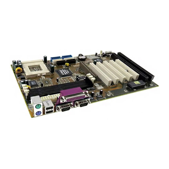
Introduction SY-5EMA Pro SY-5EMA Pro Motherboard Layout DIMM3 CPUFAN DIMM 2 PS/2 KB PS/2 Mouse Connector DIMM 1 Connector JP11 USB1 USB2 ATX Power P.B. SRAM 64Kx64 P.B. SRAM 64Kx64 (Optional) JP44 ® TAG 32Kx8 IDE 2 IDE 1 ETEQ Header EQ82C6638 AGP Slot... -
Page 7: Chapter 1 Introduction
Introduction SY-5EMA Pro Chapter 1 INTRODUCTION The SY-5EMA Pro AGP/PCI Motherboard is a high-performance ATX form-factor system board. SY-5EMA Pro uses the ® ETEQ82C663 PCI Chipset technology and supports Pentium class processors. This Motherboard is fully compatible with industry standards and adds many technical enhancements. 1-1 KEY FEATURES Ø... - Page 8 Introduction SY-5EMA Pro DRAM Controller Ø Supports 3 strips of 168-pin SDRAM unbeffured DIMM 3 x 168-pin DIMM banks support 8/16/32/64/128/256 MB unbuffered DIMM modules Ø Memory configuration: System memory: 8MB to 768MB with EDO/SDRAM SY-5EMA Pro PLATFORM FEATURES Board Size 4-layer PCB, 19x30.5cm(7.5”x12”), ATX Form Factor ®...
- Page 9 Introduction SY-5EMA Pro 5-pin Serial Infrared Device Connector Keylock 5-pin KeyLock Connector Reset 2-pin Reset Switch Connector Speaker 4-pin PC Speaker Connector TB_LED 2-pin Turbo LED Connector HDD_LED 2-pin IDE Device LED Connector PWRBT ATX Power On/Off Switch 2-pin Connector CMOS Clear Jumper CPU bus clock frequency Jumper JP9, JP10...
-
Page 10: Handling The Motherboard
Introduction SY-5EMA Pro 1-2 HANDLING THE MOTHERBOARD To avoid damage to your Motherboard, follow these simple rules while unpacking: Ø Before handling the Motherboard, ground yourself by grasping an unpainted portion of the system's metal chassis. Ø Remove the Motherboard from its anti-static packaging. Hold the Motherboard by the edges and avoid touching its components. -
Page 11: Chapter 2 Hardware Setup
Hardware Setup SY-5EMA Pro Chapter 2 HARDWARE SETUP Congratulations on your purchase of SY-5EMA Pro Super 7 Motherboard. You are about to install and connect your new Motherboard. Note: Do not unpack the Motherboard from its protective anti-static packaging until you have made the following preparations. -
Page 12: Unpacking The Motherboard
Hardware Setup SY-5EMA Pro 2-2 Unpacking the Motherboard When unpacking the Motherboard, check for the following items: Ø The SY-5EMA Pro ETEQ82C663 PCI/AGP Motherboard Ø This Quick Start Guide * Ø The Installation CD-ROM * Ø One IDE Device ATA66 Flat Cable Ø... -
Page 13: Installation Guide
Hardware Setup SY-5EMA Pro 2-3 Installation Guide We will now begin the installation of the Motherboard. Please follow the step-by-step procedure designed to lead you to a complete and correct installation. Step 1. CPU Installation ® Follow these instructions to install your Pentium class processor correctly. - Page 14 Hardware Setup SY-5EMA Pro Follow these steps to install the CPU in the Socket 7: Lift the socket handle up to a vertical position. Align the blunt edge of the CPU with the matching pinhole distinctive edge on the socket. Seat the processor in the socket completely and without forcing.
- Page 15 Hardware Setup SY-5EMA Pro Step 3. CPU Voltage Setting (SW2) ® CPU Voltage Please verify the correct voltage with your dealer before installation. Use the following tables to set SW2 to the proper "Voltage Value", according to the specifications marked on your CPU: This Motherboard comes with pre-configured setting of CPU voltage.
- Page 16 Hardware Setup SY-5EMA Pro CPU you are installing and adjust the settings on SW2 accordingly. This motherboard supports CPU core voltages from 2.0 to 3.5V in 0.1V increments. Use the following tables to set the CPU voltage jumpers SW2 to match the voltage value of your CPU: CPU Core Voltage Setting: SW2 Voltage Value 3.5V...
- Page 17 Hardware Setup SY-5EMA Pro Voltage Settings for Various Processors Processor Voltage Value: SW2 Voltage Setting Single Voltage Intel P54C - P100 :3.3V Intel P54C - P133 :3.3V Single Voltage Intel P54C - P166 :3.5V Intel P54C - P200 :3.5V Dual Voltage Intel P55C - P166 :2.8V Intel P55C - P200...
- Page 18 Hardware Setup SY-5EMA Pro Voltage Settings for Various Processors (continued) Processor Voltage Value: SW2 Voltage Setting Single Voltage Intel P54C - P100 :3.3V Intel P54C - P133 :3.3V Single Voltage Intel P54C - P166 :3.5V Intel P54C - P200 :3.5V Dual Voltage Intel P55C - P166 :2.8V...
- Page 19 Hardware Setup SY-5EMA Pro Step 4. CPU Frequency Setting (SW1) ® Host Bus Frequency Frequency Multiplier The SY-5EMA Pro Motherboard is designed to support most ® Pentium class processors currently on the market. Jumpers SW1 is used to configure the Motherboard frequency parameters to match the working frequency of your CPU.
- Page 20 Hardware Setup SY-5EMA Pro CPU FREQUENCY SETTING (SW1) Configure the SW1 jumpers to the settings that match your CPU speed. Refer to the following tables to set the Frequency Multiplier and Host Bus Frequency of your CPU: Frequency Multiplier Host Bus Frequency Host Bus Multiplier Frequency...
- Page 21 Hardware Setup SY-5EMA Pro Please refer to the following table that gives you the correct frequency settings for the specific brand and model of CPU you are installing on this Motherboard. ® Frequency Settings for Intel Processors Processor Frequency Ratio Frequency Setting Clock Clock...
- Page 22 Hardware Setup SY-5EMA Pro Frequency Settings for AMD ™ Processors (Continued) Processor Frequency Ratio Frequency Setting Clock Clock Clock Setting: SW1 AMD K5 - PR166 2.5 x 66MHz 66MHz 33MHz 1 2 3 4 5 6 AMD K6 - 166 2.5 x 66MHz 66MHz 33MHz...
- Page 23 Hardware Setup SY-5EMA Pro Frequency Settings for AMD ™ Processors (Continued) Processor Frequency Ratio Frequency Setting Clock Clock Clock Setting: SW1 AMD K6-2 380 4.0 x 95MHz 63.5MHz 31.75MHz 1 2 3 4 5 6 AMD K6-2 400 4.0 x 100MHz 66MHz 33MHz 1 2 3 4 5 6...
- Page 24 Hardware Setup SY-5EMA Pro Frequency Settings for Cyrix ™ Processors Processor Rati Frequency Frequency Setting Clock Clock Clock Setting: SW1 Cyrix 6x86 - PR166+ 2.0 x 66MHz 66MHz 33MHz 1 2 3 4 5 6 Cyrix 6x86 - PR200+ 2.0 x 75MHz 75MHz 37.5MHz 1 2 3 4 5 6 Cyrix MX - PR166**...
- Page 25 Hardware Setup SY-5EMA Pro Frequency Settings for Cyrix ™ Processors (Continued) Processor Rati Frequency Frequency Setting Clock Clock Clock Setting: SW1 Cyrix M II – 400** 3.0 x 95MHz 63.5MHz 31.75MHz 1 2 3 4 5 6 Cyrix M II - 433** 3.0 x 100MHz 66MHz 33MHz 1 2 3 4 5 6...
- Page 26 Hardware Setup SY-5EMA Pro Step 5. Set JP8,JP9,JP10 for SDRAM frequency JP8 is used to indicate the frequency of the CPU bus clock to the ETEQ chipset. JP9 and JP10 are used to determine that the SDRAM is running at the frequency of the CPU bus clock or the AGP clock.
- Page 27 Hardware Setup SY-5EMA Pro Step 7. DRAM Module Installation This Motherboard supports three DIMM banks from 8 to 256 MB with no other restrictions on memory configurations. You can install the memory in any combination without having to rely on a memory configuration table.
- Page 28 Hardware Setup SY-5EMA Pro MEMORY CONFIGURATION This Motherboard features 3 x DIMM Banks for 168-pin 3.3V unbuffered DIMM modules Your board comes with three DIMM sockets, providing support for up to 768MB of main memory using DIMM modules from 8MB to 256MB.
- Page 29 Hardware Setup SY-5EMA Pro Step 10. Front Panel Connections HDD LED ® Speaker Turbo Keylock PWRBT Power Reset Plug the computer case's front panel devices to the corresponding connectors on the Motherboard. 1. Power LED & KeyLock Plug the Power LED cable into the 5-pin Keylock connector. Some systems may feature a KeyLock function with a front panel switch for enabling or disabling the keyboard.
- Page 30 Hardware Setup SY-5EMA Pro 3. Speaker Attach the 4-pin PC speaker cable from the case to the Speaker connector on the Motherboard. 4. Turbo LED Connecting the 2-pin Turbo LED cable to the corresponding Turbo LED connector will cause the LED to light whenever the system is in Turbo mode.
- Page 31 Hardware Setup SY-5EMA Pro Step 11. Back Panel Connections All external devices such as the keyboard, printer, PS/2 mouse, modem, USB, can be plugged directly onto the Motherboard back panel. Only after you have fixed and locked the Motherboard to the computer case can you start connecting the external peripheral devices.
- Page 32 Hardware Setup SY-5EMA Pro 1. Onboard Serial Port COM1,COM2 External peripherals that use serial transmission scheme include: serial mouse, and modem. Plug the serial device cables directly into the COM1or COM2 9-pin male connector located at the rear panel of the Motherboard. 2.
- Page 33 Hardware Setup SY-5EMA Pro Wake-On-LAN (WOL) Attach the 3-pin connector from the LAN card which supports the Wake-On-LAN (WOL) function to the JP44 connector on the Motherboard. This WOL function lets users wake up the connected computer through the LAN card. Please install according to the following pin assignment: Wake-On-LAN JP44 Pin Assignment...
- Page 34 Hardware Setup SY-5EMA Pro Step 12. CPU Cooling Fan Installation After you have seated the CPU cooling fan properly on the processor, attach the 3-pin fan cable to the CPUFAN connector on the Motherboard. To avoid damage to the system, install according to the following pin assignment: CPU Cooling Fan CPUFAN Pin Assignment...
- Page 35 Hardware Setup SY-5EMA Pro Step 14. ATX Power Supply Plug the connector from the power directly into the 20-pin male ATX PW connector on the Motherboard, as shown in the following figure. ® ATX Power Warning: Follow these precautions to preserve your Motherboard from any remnant currents when connecting to ATX power supply: Turn off the power supply and unplug the power cord...
- Page 36 Hardware Setup SY-5EMA Pro Please install the ATX power according to the following pin assignment: ATX Power 3.3V 3.3V -12V 3.3V Ø Pay special care to the directionality. PS-ON PW-OK 5VSB Clear CMOS In some cases the CMOS memory may contain wrong data, follow the steps below to clear CMOS memory.
- Page 37 Hardware Setup SY-5EMA Pro Step 15. MULTI I/O ADDRESSES Default settings for multi-I/O addresses are as follows: Port I/O Address Status LPT1 378H ECP + EPP COM1 3F8H COM2 2F8H Warning: If a default I/O address conflicts with other I/O cards such as sound card, you must change one of the I/O addresses to remedy to this address conflict.
- Page 38 Troubleshooting at First Start Video (no display) related issues I built a new computer system using a Soyo board and nothing happens when turning it on, no video and no beeps from the PC speaker. What is happening and how can it be fixed? No screen and no beeps mean that your CPU and motherboard do not work at all.
- Page 39 Hardware Setup SY-5EMA Pro 2. Double-check jumpers setting on you motherboard and remove all add-on cards, unplug all hard-disk and floppy-disk drive cables and see if you can hear some beeps. If you still do not get any beeps, then try putting the motherboard on the table (to isolate it from the case) with the CPU and speaker only, and give it one more try.
- Page 40 Why? If you are sure that the modem driver has been installed correctly, then you need to install the south bridge driver from the SOYO CD, this is because Windows does not properly recognize relatively new chipsets.
- Page 41 Hardware Setup SY-5EMA Pro In Device Manager, I keep getting yellow exclamation signs on my sound port even though I have installed my sound driver several times and I could not get my sound card to work. What is wrong? It is likely that you did not have the correct driver installed.
- Page 42 Hardware Setup SY-5EMA Pro make sure the 'linear burst function' is enabled in the bios. I can not get my board to run properly. Please make sure you have the latest bios and driver from the SOYO web site at: http://www.soyo.com...
-
Page 43: Chapter 3 Bios Setup Utility
BIOS Setup Utility SY-5EMA Pro Chapter 3 BIOS SETUP UTILITY This Motherboard's BIOS setup program uses the ROM PCI/ISA BIOS program from Award Software Inc. To enter the Award BIOS program's Main Menu: Turn on or reboot the system. After the diagnostic checks, press the [Del] key to enter the Award BIOS Setup Utility. - Page 44 BIOS Setup Utility SY-5EMA Pro Hot Keys: Function keys give you access to a group of commands throughout the BIOS utility. Function Command Description Gives the list of options available for General Help each item. Restore the old values. These are the Previous values that the user started the current Values...
- Page 45 BIOS Setup Utility SY-5EMA Pro SAVE AND EXIT SETUP Select the [SAVE & EXIT SETUP] option from the Main Menu to save data to CMOS and exit the setup utility. This option saves all your changes and causes the system to reboot. R O M P C I / I S A B I O S...
-
Page 46: Standard Cmos Setup
BIOS Setup Utility SY-5EMA Pro STANDARD CMOS SETUP Select the [STANDARD CMOS SETUP] option from the Main Menu and press [Enter] key. CMOS Setup Utility – Copyright ( C ) 1984-1999 Award Software Standard CMOS Features Date (mm:dd:yy) Fri, Jan 1 1999 Item Help Time (hh:mm:ss) 1 : 22 : 12... - Page 47 BIOS Setup Utility SY-5EMA Pro 3-1.2 Hard Disks Type & Mode Choose the type and mode for the hard disks that you have already installed. Primary Setting Description Note (Secondary) Master & Slave IDE HDD Auto- Press To auto-detect the HDD’s size, Detection Enter head …...
- Page 48 BIOS Setup Utility SY-5EMA Pro 3-1.4 Others Optional Setting Description Note Video EGA/VGA Select the video mode. Default CGA 40 CGA 80 MONO (Monochrome) Halt On ALL Errors When the BIOS detects Default system errors, this function No Errors will stop the system. Select All, But Keyboard which type of error will cause All, But Diskette...
- Page 49 BIOS Setup Utility SY-5EMA Pro 3-2 Advanced BIOS FEATURES Select the [Advanced BIOS Features] option from the Main Menu and press [Enter] key. CMOS Setup Utility – Copyright ( C ) 1984-2000 Award Software Advanced BIOS Features Virus Warning Disabled Item Help CPU Internal Cache Enabled...
- Page 50 BIOS Setup Utility SY-5EMA Pro 3-2.1 Virus Warning Setting Description Note Virus Warning Disabled If set to enabled, the Paragon Default Anti-Virus. Function will scan Enabled your boot drive for boot virusses. If a boot virus is detected, the BIOS will display a warning message.
- Page 51 BIOS Setup Utility SY-5EMA Pro 3-2.4 System Boot Control Settings System Boot Setting Description Note Control Settings First Floppy Select Your Boot Device /Second/Third Priority LS/ZIP Boot Device HDD-0 SCSI CDROM HDD-1 HDD-2 HDD-3 Disabled Boot Other Disabled Select Your Boot Device Device Priority Enabled...
- Page 52 BIOS Setup Utility SY-5EMA Pro 3-2.8 Gate A20 Options Setting Description Note Gate A20 Normal Lets chipset control GateA20. Options Fast A pin in the keyboard controller Default controls GateA20. 3-2.9 Typematic Settings Typematic Settings Setting Description Note Typematic Disabled Keystrokes repeat at a rate Default Rate Setting...
- Page 53 BIOS Setup Utility SY-5EMA Pro 3-2.10 Security Option Use this feature to prevent unauthorized system boot-up or use of BIOS Setup. The following table describes the security settings. Setting Description Security Option System Each time the system is booted, the password prompt appears.
- Page 54 BIOS Setup Utility SY-5EMA Pro 3-3 Advanced Chipset FEATURES Caution: Change these settings only if you are already familiar with the Chipset. The [Advanced Chipset Features] option changes the values of the chipset registers. These registers control the system options in the computer. CMOS Setup Utility –...
- Page 55 BIOS Setup Utility SY-5EMA Pro 3-3.1 CHIPSET FEATURES SETUP CHIPSET Setting Description Note FEATURES Bank 0/1, 2/3, SDRAM This item allows you to select the Default 4/5 DRAM 10ns value in this field, depending on Timing whether the board has paged SDRAM DRAMs or EDO (extended data output) DRAMs.
-
Page 56: Chipset Features Setup
BIOS Setup Utility SY-5EMA Pro CHIPSET FEATURES SETUP (Continued) CHIPSET Setting Description Note FEATURES Memory Hole Disabled Some interface cards will map Default 15Mb Addr. their ROM address to this area. Enabled Select the size of Accelerated Default Aperture Graphics Port (AGP) aperture. The 4M, 8M, Size aperture is a portion of the PCI... - Page 57 BIOS Setup Utility SY-5EMA Pro CHIPSET FEATURES SETUP (Continued) CHIPSET Setting Description Note FEATURES PCI Dynmic Disabled When Enabled, every write Bursting transaction goes to the write buffer. Enabled Default Burstable transactions then burst on the PCI bus and nonburstable transactions don’t.
- Page 58 BIOS Setup Utility SY-5EMA Pro 3-4 INTEGRATED PERIPHERALS Caution: Change these settings only if you are already familiar with the Chipset. The [INTEGRATED PERIPHERALS] option changes the values of the chipset registers. These registers control the system options in the computer. The following screen shows setup default settings.
- Page 59 BIOS Setup Utility SY-5EMA Pro 3-4.1 IDE Device Controls IDE Controls Setting Description Note On-Chip PCI IDE Disabled Turn off the on-board Ø Primary Ø Secondary Enabled Use the on-board IDE Default mode 0-4 0 is the slowest speed Ø Primary Master PIO 4 is the fastest speed Ø...
- Page 60 BIOS Setup Utility SY-5EMA Pro 3-4.4 FDC Controls FDC Controls Setting Description Note Onboard FDD Disabled Turn off the on-board controller floppy controller Enabled Use the on-board floppy Default controller 3-4.5 Onboard Serial Ports Onboard Serial Setting Description Note Ports Onboard Disabled Serial Port 1 /...
- Page 61 BIOS Setup Utility SY-5EMA Pro 3-4.6 Onboard Parallel Ports Onboard Parallel Setting Description Note Ports Onboard Parallel Disabled Choose the printer I/O Port address. 378/IRQ7 Default 3BC/IRQ7 278/IRQ5 Parallel Port Mode Normal The mode depends on your Default external device that connects to this port.
-
Page 62: Power Management Setup
BIOS Setup Utility SY-5EMA Pro 3-5 POWER MANAGEMENT SETUP The [POWER MANAGEMENT SETUP] sets the system's power saving functions. CMOS Setup Utility – Copyright ( C ) 1984-2000 Award Software Power Management Setup ACPI Function Enabled Item Help Power Management Press Enter Menu Level 4 PM Control by APM... - Page 63 BIOS Setup Utility SY-5EMA Pro After you have completed the Power Management Setup, press [Esc] to return to the Main Menu. 3-5.1 Power Management Controls Power Setting Description Note Management Controls ACPI Disabled function Enabled ACPI (Advanced Configuration Default Power Management Interface) Power Lets you define the HDD and Default...
- Page 64 BIOS Setup Utility SY-5EMA Pro Power Management Controls (Continued) Power Setting Description Note Management Controls MODEM Use Assigns an IRQ# to the modem Default device. 3-11, NA Soft-Off by Instant-off Default PWR-BTTN Delay 4 Sec. Turns off the system power 4 seconds after pushing the power button.
- Page 65 BIOS Setup Utility SY-5EMA Pro Wake Up Setting Description Note Events PowerOn by Disabled If enabled any PCI interrupt will PCI Card wake up the system. Enabled Default Modem Ring Disabled An input signal on the serial Ring Resume Indicator (RI) line (in other words, Enabled Default an incoming call on the modem)
-
Page 66: Pnp/Pci Configuration Setup
BIOS Setup Utility SY-5EMA Pro 3-6 PNP/PCI CONFIGURATION SETUP This option sets the Motherboard's PCI Slots. CMOS Setup Utility – Copyright ( C ) 1984-2000 Award Software PnP/PCI Configurations PNP OS Installed Item Help Reset Configuration Data Disabled Menu Level 4 Resources Controlled By Auto (ESCD) x IRQ Resources... - Page 67 BIOS Setup Utility SY-5EMA Pro 3-6.1 PNP/PCI Configuration Controls PNP/PCI Setting Description Note Controls PnP OS Set this field to [Yes] if you Installed are running Windows 95, which is PnP compatible. If the OS you are running Default (If there is any does not support PnP doubt, set this configuration.
- Page 68 BIOS Setup Utility SY-5EMA Pro PNP/PCI Configuration Setup (Continued) PNP/PCI Setting Description Note Setup How to set the BIOS to release the IRQ to the PnP Interrupt pool: Interrupt Line PnP / PCI configuration Integrated Peripherals IRQ 15 IRQ 15: PCI / ISA PnP On-Chip Secondary PCI IDE: disabled IRQ 14 IRQ 14: PCI / ISA PnP On-Chip Primary PCI IDE: disabled Interrupt 12 will be released by the PnP...
- Page 69 BIOS Setup Utility SY-5EMA Pro 3-6.2 MULTI I/O ADDRESSES Default settings for multi-I/O addresses are as follows: Port I/O Address Status LPT1 378H ECP/EPP COM1 3F8H COM2 2F8H Warning: If a default I/O address conflicts with other I/O cards such as sound card, you must change one of the I/O addresses to remedy to this address conflict.
- Page 70 BIOS Setup Utility SY-5EMA Pro 3-7 LOAD Fail-safe DEFAULTS Select the [Load Fail-Safe Defaults] option from the Main Menu to load the system values you have previously saved. This option is recommended if you need to reset the system setup and to retrieve the old values. CMOS Setup Utility –...
- Page 71 BIOS Setup Utility SY-5EMA Pro 3-8 LOAD Optimized DEFAULTS Select the [Load Optimized Defaults] option from the Main Menu to load the system values you have previously saved. This option is recommended if you need to reset the system setup and to retrieve the old values. CMOS Setup Utility –...
- Page 72 BIOS Setup Utility SY-5EMA Pro 3-9 SUPERVISOR PASSWORD Based on the setting you have made in the [Security Option] of the [BIOS FEATURES SETUP] section, the password prevents access to the system or the setup program by unauthorized users. Follow this procedure to set a new password or disable the password: Choose [BIOS FEATURES SETUP] in the Main Menu and press [Enter].
-
Page 73: Load Setup Defaults
BIOS Setup Utility SY-5EMA Pro Enter your new password and press [Enter]. The following message appears, prompting to confirm the new password: Confirm Password: Re-enter your password and then press [Enter] to exit to the Main Menu. This diagram outlines the password selection procedure: ↔... -
Page 74: Ide Hdd Auto Detection
BIOS Setup Utility SY-5EMA Pro 3-11 IDE HDD AUTO DETECTION This Main Menu function automatically detects the hard disk type and configures the [Standard CMOS Features] accordingly. CMOS Setup Utility – Copyright ( C ) 1984-2000 Award Software IDE Primary Master IDE HDD Auto-Detection Press Enter Item Help... -
Page 75: Chapter 4 Drivers Installation
Step 1. Insert the SOYO CD into the CD-ROM drive The SOYO CD will auto-run, and the SOYO CD Start Up Menu will be as shown. If you use Windows NT, the SOYO-CD will not detect your motherboard type. - Page 76 Drivers Installation SY-5EMA Pro The user's manual files included on the SOYO CD are in PDF (Postscript Document) format. In order to read a PDF file, the appropriate Acrobat Reader software must be installed in your system. Note: The Start Up program automatically detects if the Acrobat Reader utility is already present in your system, and otherwise prompts you on whether or not you want to install it.
- Page 77 Drivers Installation SY-5EMA Pro Step 2. Install Drivers and Utilities The following describes the best way of installing Windows 95 or Windows 98 on your 5EMA Pro Motherboard: The following BIOS default settings should not be changed: Ø 1. The ‘OnChip USB Controller’ item under ‘Chipset features Setup’ is set to enabled. 2.
- Page 78 Step 3. Check the Latest Releases Click the 'Check the latest Releases' button to go the SOYO Website to automatically find the latest BIOS, manual and driver releases for your motherboard. This button will only work if your computer is connected to the internet through a network or modem connection.
- Page 79 Drivers Installation SY-5EMA Pro...