Table of Contents
Advertisement
Advertisement
Table of Contents

Related Manuals for Ryobi RPHD43O


Summary of Contents for Ryobi RPHD43O
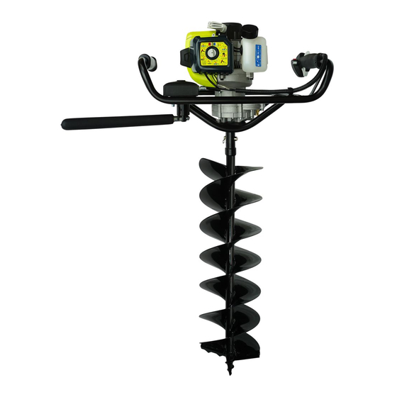
- Page 1 OPERATOR’S MANUAL POST HOLE DIGGER RPHD43...
- Page 2 Important! It is essential that you read the instructions in this manual before assembling, operating and maintaining this product. Subject to technical modification.
-
Page 3: Product Description
PRODUCT DESCRIPTION Figure 1 Figure 2 LEGEND 1. Fuel tank 10. Primer bulb 19. Cylinder cover 2. Engine switch 11. Airbox 20. Heat deflector grille 3. Throttle lock button 12. Airbox lock knob 21. Muffler cover 4. Trigger lock 13. Safety device control box 22. - Page 4 ASSEMBLY MOUNTING THE SAFETY BAR ADDING THE TOOL Figure 3 Figure 6 Align the safety bar into the the seat on the safety Align the engine drive shaft into the seat on the auger bit. device spindle. Figure 4 Figure 7 Secure using the gudgeon pin and cotter pin Fasten the nylock nut using the spanner supplied.
-
Page 5: Starting Instructions
STARTING INSTRUCTIONS FUEL MIX RATIO Push primer bulb x 10. Move choke lever to “START” postion. Lock throttle by steps “1, 2, 3”. Pull untill engine attempts to start Move choke lever to “RUN” (Max 6 pulls). position. Pull to start (Max 2 pulls) then full Hold “STOP”... -
Page 6: Operation
OPERATION Figure 10 Figure 12 HANDLE LEVEL Correct operating position is with the two handles DO NOT operate with either bellow waist level, which will ensure full control of one or two handles above waist the digger can be maintained. level. -
Page 7: Maintenance
MAINTENANCE GEARBOX LUBRICATION SPARK PLUG Figure 15 Figure 14 Pressure release screw Spark plug Air filter retainer AIR FILTER Figure 17 Figure 16 Airbox lock knob Foam filter element SPARK ARRESTOR Figure 18 Spark arrestor... -
Page 8: General Safety Rules
Thank you for buying a Ryobi post hole digger. Your new tool has been engineered and manufactured to Ryobi’s high standard for dependability, ease of operation and operator safety. If properly cared for, it will give you years of rugged, trouble free performance. - Page 9 It has been reported that vibrations from hand-held tools may contribute to a condition called Raynaud’s Syndrome in certain individuals. Symptoms may include tingling, numbness and blanching of fingers, usually apparent upon exposure to cold. Hereditary factors, exposure to cold and dampness, diet, smoking and work practices are all thought to contribute the development of these symptoms.
- Page 10 Never operate in a horizontal angle. The post hole digger should only be operated with the auger at a 90° angle to the ground. Always keep the handles dry and clean. Before starting to drill make sure the bit is not obstructed. Always work in a firm-footed and safe position.
- Page 11 SYMBOL NAME EXPLANATION Gloves Wear non-slip, heavy-duty gloves. No smoking Do not smoke when mixing fuel or filling fuel tank. Petrol Use unleaded petrol intended for motor vehicle use with an octane rating of 91 or higher. Use synthetic 2-stroke oil for air cooled engines. Mix the fuel mix thoroughly and also each time before Mix petrol and oil refuelling.
-
Page 12: Packing List
1 x 76ml 2-Stroke Synthetic Oil 3 x Gudgeon Pins with Cotter Pins 1 x Operator’s Manual 1 x Safety bar 1 x RPHD43O Engine Assembly FEATURES KNOW YOUR POST HOLE DIGGER See figure 1 & 2 The safe use of this product requires an understanding of the information on the product and in this operator’s manual as well as a knowledge of the project you are attempting. - Page 13 ENGINE SWITCH This post hole digger is built with a lock-on engine switch which is used in combination with the recoil starter grip to start the engine. It is also used to turn the engine off. THROTTLE LOCK The throttle lock is used to help the engine on cold starts. THROTTLE TRIGGER The throttle trigger helps the operator control the speed of the auger to suit various ground conditions.
-
Page 14: Operation Rules
FITTING THE AUGER BITS See figure 6 & 7 Align the engine drive shaft into the seat on the auger bit and secure it using the appropriate gudgeon pin and cotter pin provided. NOTE: Your post hole digger is supplied with a 300mm extension shaft to be used for deeper hole digging. -
Page 15: Filling The Tank
FUEL AND REFUELING SAFETY Always handle fuel with care, it is highly flammable. Always refuel outdoors where there are no sparks and flames. Do not inhale fuel vapours. Do not let petrol or oil come in contact with your skin. Keep petrol and oil away from the eyes. -
Page 16: Starting And Stopping
STARTING AND STOPPING WARNING! Never start or run the engine inside a closed or poorly ventilated area; Breathing exhaust fumes can kill. WARNING! Do not have the auger bit attached when starting a cold engine. The auger bit may rotate when the engine starts with the throttle lock engaged. - Page 17 Stand comfortably with both feet of firm ground having the left foot slightly forward of the right foot. Lean the frame of the engine in front of the safety bar on your left thigh. Always keep a firm grip with both hands while in operation. The post hole digger should be held at a comfortable position with the left and right handles no higher than waist level.
-
Page 18: Reduction Gearbox
Stop the engine and allow it to cool before making adjustments or completing any maintenance. You may make adjustments and repairs described here. For other repairs, have the post hole digger serviced by an authorised service agent. Consequences of improper maintenance may include excess carbon deposits resulting in loss of performance and discharge of black oily residue dripping from the muffler. -
Page 19: Storing The Product
NOTE: Make sure the filter is seated properly inside the cover. Installing the filter incorrectly will allow dirt to enter the engine, causing rapid engine wear. Reinstall the airbox cover and tighten lock knob to secure. FUEL TANK WARNING! A leaking fuel cap is a fire hazard and must be replaced immediately. The fuel cap contains a sealing gasket and a check valve to ventilate built up fuel gasses. -
Page 20: Troubleshooting
TROUBLESHOOTING If these solutions do not solve the problem, contact your authorised service dealer. PROBLEM POSSIBLE CAUSE SOLUTION Engine will not No spark. Check spark: remove spark plug, reattach the spark start. plug cap and lay spark plug on metal cylinder. Pull the starter rope and watch for spark at spark plug tip. - Page 21 PROBLEM POSSIBLE CAUSE SOLUTION The auger Idle speed is set too Turn the idle speed screw counter clockwise to attachment high. reduce the idle RPM and stop the auger attachment. turns at idle. Gearbox clutch is Contact a service dealer for adjustment and inoperable.
-
Page 22: Specifications
SPECIFICATIONS Model: RPHD43O Vibration, right grip: Idling 12.6 m/s Engine type: Air cooled 2-stroke Racing 5.0 m/s 43 cc Engine displacement: Uncertainty 1.5 m/s Max Engine power: 1.25 kw / 6500 rpm Gearbox reduction ratio: 40:1 Vibration, left grip: Idling 14.1 m/s Idle speed: 2800±280 rpm... - Page 24 Techtronic Industries (Australia) Pty. Ltd. 31 Gilby Road, Mt Waverley VIC 3149, Australia Techtronic Industries New Zealand Ltd. 2 Landing Drive, Auckland Airport, Mangere, New Zealand 2022...