Shure SCM268 Manual
Four-channel microphone mixer
Hide thumbs
Also See for SCM268:
- Guía del usuario (13 pages) ,
- User manual (13 pages) ,
- User manual (11 pages)
Table of Contents
Advertisement
Quick Links
Download this manual
See also:
User Manual
Advertisement
Table of Contents

Related Manuals for Shure SCM268


Summary of Contents for Shure SCM268
- Page 1 SCM268 Four-Channel Microphone Mixer The Shure four-channel microphone mixer, SCM268, user guide. Version: 4 (2019-G)
-
Page 2: Table Of Contents
Shure Incorporated Table of Contents Installation SCM268Four-Channel Microphone Mixer Supplied Hardware Rackmount Installation IMPORTANT SAFETY INSTRUCTIONS Internal Modifications General Description Internal Modifications Features Disassembly Front Panel Low-Cut Filter Rear Panel Phantom Power Disable Line Pad Gain Control Hot Mic Pad... -
Page 3: Scm268Four-Channel Microphone Mixer
Shure Incorporated SCM268 Four-Channel Microphone Mixer IMPORTANT SAFETY INSTRUCTIONS READ these instructions. KEEP these instructions. HEED all warnings. FOLLOW all instructions. DO NOT use this apparatus near water. CLEAN ONLY with dry cloth. DO NOT block any ventilation openings. Allow sufficient distances for adequate ventilation and install in accordance with the manufacturer’s instructions. -
Page 4: General Description
The safety certifications do not apply when the operating voltage is changed from the factory setting. General Description The Shure Model SCM268 is a transformerbalanced, fourchannel microphone mixer. Its simple, compact design delivers su perior performance and exceptional sound quality with low noise and a flat frequency response. -
Page 5: Rear Panel
This LED illuminates when the unit is plugged in and receiving power. The SCM268 does not have a power switch. To turn the unit off, unplug the power cord or use an external power strip with a switch. However, it can remain plugged in as it uses very little power when idle. -
Page 6: Gain Control
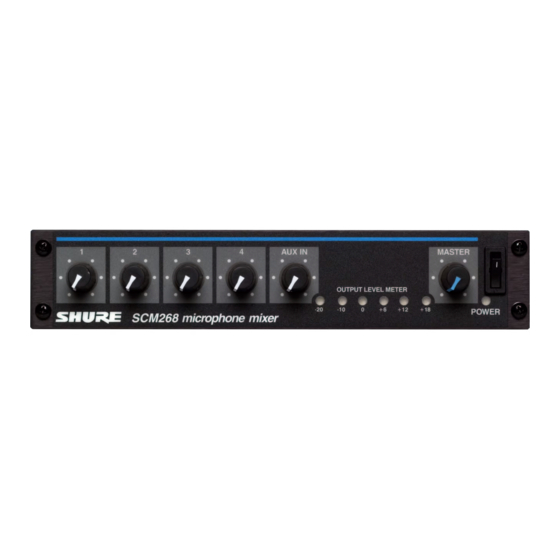
The six LEDs on the front panel labeled OUTPUT LEVEL METER illuminate to reflect the peak level of the mixed output signal from the SCM268 (in reference to balanced line output) in dBu (0 dBu = 0.775 V). Use the master gain control (MASTER) to adjust peak levels, as indicated by the LEDs. The red LED illuminates when the out... -
Page 7: Phantom Power
Use it when connecting these types of microphones to the SCM268. Phantom power does not affect the operation of balanced dynamic microphones. With phantom power on, they can be connected to the SCM268 in combina tion with condenser microphones that do use it. -
Page 8: Connections
Connections The following diagram illustrates a few of the many types of connections possible with the SCM268. Note that nothing is con nected to the channel 4 microphone input (MIC LEVEL INPUT 4). This is because channel 4 is being used for the consumer- level equipment connected to the channel 4 auxiliary level input (AUX LEVEL INPUT 4). -
Page 9: Installation
4 wood screws, 1/2 in. (1.25 cm). For fixed installations. Rackmount Installation The SCM268 can be mounted as a single unit or dual-mounted with either another SCM268 or another Shure half-rack unit such as the SCM262 or DFR11EQ. Attach the rackmount brackets using one of the following methods: Single-unit (half-rack) installation: Attach the short and long rackmount brackets to the SCM268 with eight (8) of the supplied bracket screws. - Page 10 Shure Incorporated Dual-mounted installation: Connect the two units together side-by-side using two (2) straddle brackets. The brackets should straddle the recessed edges on the top and bottom of each chassis. Fasten them using eight (8) bracket screws. Be sure to use both straddle brackets-one on the top and one on the bottom.
- Page 11 Shure Incorporated Fixed Installation To permanently affix the SCM268 above or below a table, shelf, or counter top, use the following steps: Fasten the straddle brackets to the recessed edges of the chassis using four (4) bracket screws. Top mount: Fasten the straddle brackets to the bottom of the unit.
-
Page 12: Internal Modifications
Slide the back panel and pc board out from the rear of the chassis. When reassembling the SCM268, DO NOT OVERTIGHTEN the knob retainer nuts. Use a minimal amount of force to secure the nut (0.6-0.8 N m (5-7 in lb)). Damage to the internal components will result if too much force is used. -
Page 13: Phantom Power Disable
Shure Incorporated Channel Remove Resistor from: Place 0µF to 33µF Capacitor in: To select a particular corner frequency for the low cut filter, remove the R18, R28, R38, or R48 resistor for a given channel as specified above.Then, in the corresponding pc board location (X17, X27, X37, or X47), place a capacitor of the specified value (polarity does not matter). -
Page 14: Line Pad
Shure Incorporated Line Pad To insert a 50 dB line pad for a given microphone input, remove the specified resistor and short the solder points at the speci fied pc board locations. Refer to the following table: Channel Remove Resistors:... -
Page 15: Specifications
Shure Incorporated Specifications Frequency Response at 1 kHz Mic/Line Switch 150 Hz to 20 kHz ±2 dB Aux Input 20 Hz to 20 kHz ±2 dB Low-Cut Filter -6 dB/octave below 80 Hz Total Harmonic Distortion 1 kHz, +4 dBu out, mix output (MASTER) at +0 dB <0.25%... -
Page 16: Optional Accessories And Replacement Parts
53E8484 Certifications This product meets the Essential Requirements of all relevant European directives and is eligible for CE marking. The CE Declaration of Conformity can be obtained from: www.shure.com/europe/compliance Authorized European representative: Shure Europe GmbH Headquarters Europe, Middle East & Africa Department: EMEA Approval Jakob-Dieffenbacher-Str.