Table of Contents
Advertisement
Quick Links
Advertisement
Table of Contents
Troubleshooting

Related Manuals for Canon W6400 Series


Summary of Contents for Canon W6400 Series
- Page 1 Service Manual W6400 Series W6400 Apr 5 2005...
- Page 3 Canon will release technical information as the need arises. In the event of major changes in the contents of this manual over a long or short period, Canon will issue a new edition of this manual.
- Page 4 Introduction Symbols Used This documentation uses the following symbols to indicate special information: Symbol Description Indicates an item of a non-specific nature, possibly classified as Note, Caution, or Warning. Indicates an item requiring care to avoid electric shocks. Indicates an item requiring care to avoid combustion (fire). Indicates an item prohibiting disassembly to avoid electric shocks or problems.
- Page 5 Introduction The following rules apply throughout this Service Manual: 1. Each chapter contains sections explaining the purpose of specific functions and the relationship between electrical and mechanical systems with reference to the timing of operation. In the diagrams, represents the path of mechanical drive; where a signal name accompanies the symbol , the arrow indicates the direction of the electric signal.
-
Page 7: Table Of Contents
Contents Contents Chapter 1 PRODUCT DESCRIPTION 1.1 Product Overview ............................1- 1 1.1.1 Product Overview ..............................1- 1 1.2 Features ..............................1- 2 1.2.1 Features .................................. 1- 2 1.2.2 Printhead ................................. 1- 2 1.2.3 Ink Tank................................... 1- 2 1.2.4 Cutter Unit ................................1- 2 1.2.5 Roll Holder................................ - Page 8 Contents 2.2.4 Print position adjustment............................2- 7 2.2.5 Head Management ..............................2- 8 2.2.6 Overheating Protection Control of Printhead ......................2- 8 2.2.7 Pause between Pages .............................2- 8 2.2.8 White Raster Skip ..............................2- 8 2.2.9 Sleep Mode................................2- 8 2.3 Printer Mechanical System......................... 2- 9 2.3.1 Outline..................................2- 9 2.3.1.1 Outline......................................
- Page 9 Contents 4.3.4 Outer covers ................................4- 4 4.3.5 Driving unit................................4- 8 4.3.6 Ink tube unit ................................4- 9 4.3.7 Carriage unit ................................4- 12 4.3.8 Feeder unit ................................4- 15 4.3.9 Purge unit ................................4- 15 4.3.10 Head management sensor ..........................4- 16 4.3.11 Ink tank unit .................................
- Page 10 Contents 6.1.4.2 E0200D/ E02016/ Cut sheet end error............................. 6- 6 6.1.4.3 E0200A/ E0200B/ E0200C/ E0200E/ E0200F/ E02010/ E02017/E02018/ Registration sensor error ........6- 6 6.1.4.4 E02015/ Cutter error ................................6- 6 6.1.4.5 E02400/ E02401/ E02402/ E02403/ Path mismatch error ....................... 6- 7 6.1.4.6 E02405/ E02406/ E02407/ Borderless printing error .......................
- Page 11 Contents Chapter 8 ERROR CODE 8.1 Outline ................................8- 1 8.1.1 Outline ..................................8- 1 8.2 Warning Table ............................8- 2 8.2.1 Warnings ................................. 8- 2 8.3 Error Table..............................8- 3 8.3.1 Errors..................................8- 3 8.4 Sevice Call Table............................8- 5 8.4.1 Service call error list ..............................8- 5...
- Page 12 Contents...
-
Page 13: Chapter 1 Product Description
Chapter 1 PRODUCT DESCRIPTION... - Page 15 Contents Contents 1.1 Product Overview ................................1-1 1.1.1 Product Overview ..................................1-1 1.2 Features ..................................1-2 1.2.1 Features ......................................1-2 1.2.2 Printhead ...................................... 1-2 1.2.3 Ink Tank ....................................... 1-2 1.2.4 Cutter Unit ....................................1-2 1.2.5 Roll Holder....................................1-2 1.2.6 Consumables ....................................1-3 1.3 Product Specifications..............................1-4 1.3.1 General Specifications .................................
-
Page 17: Product Overview
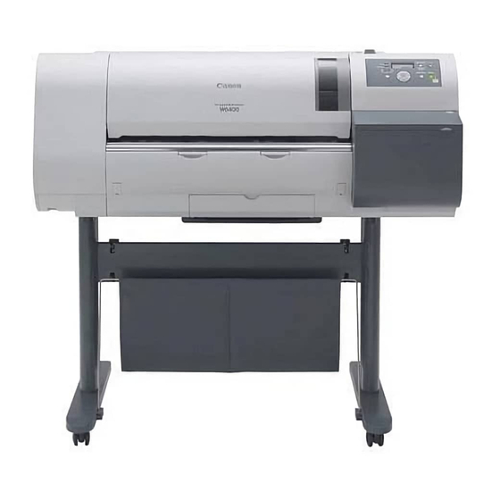
Chapter 1 1.1 Product Overview 1.1.1 Product Overview 0008-6296 This printer is a large format printer which is capable of high-speed, photo-quality printing on large-size paper up to 24 inches wide. The printer is a desktop type. The printer is capable of output to either roll media or cut sheet. IEEE1394 or 10Base-T/100Base-TX port (option) USB port... -
Page 18: Features
Chapter 1 1.2 Features 1.2.1 Features 0008-6297 - Light and compact body made possible by rear feeding of roll media. - Four-sides borderless printing support (roll media) eliminates tedious cutting and simplifies poster creation. - High quality photo finish with 2400 x 1200 dpi maximum resolution using highly lightfast, water-proof, and ozone-proof six color (C, M, Y, Bk, MBk, PC, PM) pigment ink. -
Page 19: Consumables
Chapter 1 F-1-5 1.2.6 Consumables 0008-6302 Printhead This consumable printhead is the same as the printhead shipped with the printer. F-1-6 Ink tank Seven types of consumable ink tank are available in six colors: Black (Bk), Matte Black (MBk), Photo Cyan (PC), Cyan (C), Photo Magenta (PM), Magenta (M), and Yellow (Y). -
Page 20: Product Specifications
Chapter 1 1.3 Product Specifications 1.3.1 General Specifications 0008-6303 Type Bubble jet printer (Desktop type) Feeding system Roll media: Manual (rear setting) / Cut sheet: Manual (front setting) Feeding capacity Roll media: 1 roll (outer diameter: 150 mm or less) / Optional roll holder: inner diameter of the paper tube: 50.8 mm (2") / Optional roll holder: inner diameter of the paper tube: 76.2 mm (3") / Cut sheet: 1 sheet... - Page 21 Chapter 1 Ink tank BCI-1431: Bk, PC, C, PM, M / BCI-1451: MBk, Y / Ink type: Pigment ink / Ink capacity: Approx. 130 ml Detection functions (Cover Head cap position detection: Yes / Covers open/close detection: system) Detection functions (Ink Ink tank detection: Yes / Ink level detection: Yes / Maintenance passage system) cartridge detection: Yes / Waste ink full detection: Yes /...
-
Page 22: Detailed Specification
Chapter 1 1.4 Detailed Specification 1.4.1 Printing Speed and Direction 0009-9412 Image is used by enlarging JIS SCID No.5 (ISO) to A1 full size. T-1-1 Media type Mode Print- Printing Print Print speed *1 pass direction resolution (dpi) Plain paper, Plain paper (High Draft 2-pass Bi-directional... - Page 23 Chapter 1 Twisted-pair shielded cable, 5.0 m max. Compliance with USB standards Wire materials AWG No. 28, data wire pair (AWG: American Wire Gauge) AWG No. 20 to No. 28, wire pair 5) Interface connector Printer side: USB standards, series B receptacle Cable side: USB standards, series B plug b.
-
Page 24: Names And Functions Of Components
Chapter 1 1.5 Names and Functions of Components 1.5.1 Front 0008-6306 Upper cover Thi s cover is opened whe n installing the printhead , sets cut sheets , r emoving pape r jams inside the printer , and other operations. Paper delivery assist guide Pull out when printing. -
Page 25: Carriage Unit
Chapter 1 1.5.3 Carriage unit 0008-6308 Carriage cover Printhead lock cover This cover protects the carriage . This cover is use d t o loc k the Thi s cove r i s opened when printhead. This is opened when installing the printhead. -
Page 26: Basic Operation
Chapter 1 1.6 Basic Operation 1.6.1 Operation Panel 0008-6310 This section describes the function of the buttons and the meaning of the LEDs on the operation panel. Button Lamp Information Power Information Power Data Data Message Message Cleaning Cleaning (3sec) (3sec) Stop/Eject Online... -
Page 27: Change Of Printer Status
Initializing a preset period of time. When the printer wakes from Sleep mode, it returns to the same state. Canon W6400PG Key operations and print commands S/C ver:XX.XX Online Offline MAIN MENU... - Page 28 Chapter 1 Head Cleaning MAIN MENU Head Cleaning A Head Cleaning B Force Cutting Media Type *1 Plain Paper Media detail setup menu (Med.Detail Set.) Change Bk Ink Type *2 Rep. Ink Tank *3 Printing adjustment menu (Adjust Printer) Interface setup menu (Interface Setup) Maintenance Replace P.head *2 Move Printer *2...
- Page 29 Chapter 1 Media detail setup menu *1 Med.Detail Set. (Plain Paper) VacuumStrngth Drying_Time Weak Standard 30 seconds Strong 1 min. Very Strong (3, 5, 10, 30 min.) Standard Cutter 60 min. Enable Scan Wait Time Disable Cut Speed 1 sec. Standard (3, 5, 7 sec.) Fast...
- Page 30 Chapter 1 Printing adjustment menu Adjust Printer Printhead Adj. Advanced Adj. Standard Adj. Auto Print Feed Priority Band Joint Print Length Adjust Band Standard Adj. Advanced Adj. Fine Tuning (-3) - (0) - (3) Adjust Length *1 (-0.70 ) - (0.00 ) - (0.70 Color Calib.
- Page 31 Chapter 1 Interface setup menu (1/2) Interface Setup EOP Timer 10 sec. 30 sec. (1, 2, 5, 10, 30 min.) 60 min. TCP/IP *1 TCP/IP (On) IP Mode Manual Automatic Protocol *2 IP Setting *3 DHCP IP Address (0-255. 0-255. 0-255. 0-255) BOOTP Subnet Mask (0-255.
- Page 32 Chapter 1 Interface setup menu (2/2) AppleTalk *1 Ethernet Driver *1 Auto Detect Comm. Mode Half Duplex Full Duplex Ethernet Type 10 Base-T 100 Base-TX Spanning Tree Not Use MAC Address (XXXXXXXXXXXX) Init. Settings * Default values are underlined *1 Displayed only when Network board is installed F-1-20 System setup menu System Setup...
- Page 33 Chapter 1 Information menu Information Version S/C Ver. (S/Boot Ver., E/C Ver., E/C Rel Ver.) E/Boot Ver. RAM size Ext. Interface IEEE1394 MAC Address *1 000085XXXXXX Error Log 1:XXXXX 2:XXXXX Job Log Job Log 1 Document Name (User Name, Page Count, Job Status Print Start Time, Print End Time Print Time, Print Size, Media Type Interface)
-
Page 34: Safety And Precautions
Chapter 1 1.7 Safety and Precautions 1.7.1 Safety Precautions 1.7.1.1 Moving Parts 0008-6315 Be careful not to get your hair, clothes, or accessories caught in the moving parts of theprinter. These include the carriage unit, carriage belt, ink tube and flexible cable activated bythe carriage motor; feed motor-driven feed roller and pinch roller; and purge motordrivenpurge unit. - Page 35 Chapter 1 Photo Cyan ink Glycerine 56-81-5, Ethylene glycol 107-21-1, Heterocyclic compound, Triol Magenta ink Glycerine 56-81-5, Heterocyclic compound Cyan ink Glycerine 56-81-5, Ethylene glycol 107-21-1, Heterocyclic compound, Copper compound Yellow ink Glycerine 56-81-5, Glycol, Lactum Since this ink contains pigment, stains will not come out of clothing. Maintenance-jet tray Platen (Borderless printing ink...
-
Page 36: Electrical Parts
Chapter 1 Platen unit/Carriage unit/ Main rail unit Upper cover Purge unit F-1-25 1.7.1.3 Electrical Parts 0008-6317 The electrical unit of the printer is activated when connected to the AC power supply. At the rear of the printer are the system controller, engine controller, power supply and interface connector. The head relay PCB and carriage relay PCB are incorporated in the carriage unit, and the operation panel is located on the upper right cover. -
Page 37: Other Precautions
Chapter 1 1.7.2 Other Precautions 1.7.2.1 Printhead 0008-6318 1. How to handle the printhead Do not open the printhead package until you are ready to install the head. When installing the printhead in the printer, hold the knob, and then remove the protective material and protective cap, in that order. Do not replace the protective cap once you have removed it from the printhead, since the cap may scratch the nozzles. -
Page 38: Handling The Printer
Chapter 1 When you press down the ink tank cover, the needle enters the ink supply unit, which allows ink to flow between the printer and ink tank. Do not raise or lower the ink tank lever, except when replacing the ink tank. Ink tank Ink tank cover Ink port... -
Page 39: Precautions When Servicing Printer
Chapter 1 4. Refilling the ink After removing the ink in the printer according to the automatic or manual ink draining procedure to disassemble, reassemble, or transport/ship the printer, refill the ink as soon as possible upon completion of those tasks. If the ink remaining in the printer after the removal has dried up, the ink deposits on the surfaces of the components may cause damage or abnormal operation. -
Page 41: Chapter 2 Technical Reference
Chapter 2 TECHNICAL REFERENCE... - Page 43 Contents Contents 2.1 Basic Operation Outline..............................2-1 2.1.1 Printer Block Diagram ................................. 2-1 2.1.2 Print Signal Sequence .................................. 2-1 2.1.3 Print Driving ....................................2-3 2.2 Firmware ..................................2-5 2.2.1 Power On/Off....................................2-5 2.2.2 Power Off..................................... 2-5 2.2.3 Print Control....................................2-6 2.2.4 Print position adjustment ................................2-7 2.2.5 Head Management ..................................
- Page 44 Contents 2.4.6.1 Power supply block diagram..................................2-29 2.5 Detection Functions Based on Sensors ........................2-30 2.5.1 Sensors for covers ..................................2-30 2.5.2 Ink passage system..................................2-31 2.5.3 Carriage system..................................2-33 2.5.4 Paper path system ..................................2-34...
-
Page 45: Basic Operation Outline
Chapter 2 2.1 Basic Operation Outline 2.1.1 Printer Block Diagram 0008-6327 A block diagram of the printer is shown in below. Carriage unit J1001 J214 J206 J205 Carriage relay PCB J713 J716 J711 Engine controller J203 J212 J213 J715 J714 J709 J708 Head... - Page 46 Chapter 2 Image data Host computer Mask pattern data Heat pulse Optional software Printer driver Command data RIP etc. PCI bus Data bus Universal sirial bus Interface unit Expansion c, j ASIC EEPROM Operation Image processing panel c, j unit FLASH ROM c, j DDR-SDRAM...
-
Page 47: Print Driving
Chapter 2 i) The CPU in the engine controller manages the overall print drive operations while monitoring the status of the printer components based on the adjustment values stored in the EEPROM. The SDRAM is used as work memory. j) The CPU in the system controller manages the overall image processing operations while controlling key operation and message display based on the adjustment values stored in the EEPROM. - Page 48 Chapter 2 150dpi Linear scale CRENCA CRENCB 2400dpi Internal signal 2400dpi HDCLKN O_DATABK1 Data of block 0 Data of block 2 Data of block 4 Data of block 22 O_DATABK2 Data of block 0 Data of block 2 Data of block 4 Data of block 22 E_DATABK1 Data of block 0...
-
Page 49: Firmware
Chapter 2 2.2 Firmware 2.2.1 Power On/Off 0008-6330 1. Power On The initialization sequence when the power is turned on and before the printer enters the online state is shown in the flow chart below. The printer requires about 2 minutes* to perform the initialization sequence. * This does not include the time required for supplying ink and cleaning after storage for an extended period of time. -
Page 50: Print Control
Chapter 2 * Hold down for at least 1 second Power button OFF Cut sheet "Shut Down.." is Media detection shown on display Roll media Discharge operation Uppercover / Right cover lock Engine controller data * Writing to EEPROM backup Uppercover / Right cover lockrelease * Writing to EEPROM... -
Page 51: Print Position Adjustment
Chapter 2 T-2-2 Mode Print Processing Print Print direction Media type resolution resolution (ppi) pass (dpi) Draft 1200x1200 Bi-directional Plain paper, Plain paper (High Quality) 1200x1200 Bi-directional Newspaper Proofing Paper 1, Newspaper Proofing Paper 2, Newspaper Proofing Paper 3, Coated Paper, Heavy Coated Paper, Extra Heavy Coated Paper, Color Coated Paper,... -
Page 52: Head Management
Chapter 2 2.2.5 Head Management 0009-8769 This printer has a head management function to detect any non-discharging nozzle. When a non-discharging nozzle is detected, the printer performs the printhead cleaning operations. Also, changing the mask pattern used for printing automatically allows non-discharging nozzles to be backed up by other nozzles. -
Page 53: Printer Mechanical System
Chapter 2 2.3 Printer Mechanical System 2.3.1 Outline 2.3.1.1 Outline 0008-6339 The printer mechanical system can be roughly divided into two major components: the ink passage and paper path. The ink passage consists of ink tank unit and a carriage unit where printhead are installed, purge unit, and maintenance cartridge and performs the supply, circulation, and suction/removal of ink. -
Page 54: Ink Tank Unit
Chapter 2 Mechanical Drive Unit Ink or air flow Joint Carriage unit Joint Ink tank Suction pump Ink supply valve Joint Sub buffer Maintenance cartridge F-2-8 a) Ink supply from ink tank to ink supply valve The ink tank contains ink which is supplied to the printhead. Ink flows from the ink tank to the ink supply valve due to the fluid level difference. -
Page 55: Carriage Unit
Chapter 2 Notches for preventing incorrect installation Ink port Air passage EEPROM Notches for preventing incorrect installation Ink tank F-2-9 e) Ink supply valve The ink supply valve is located between the ink tank and ink tube. This valve presents ink leakage from occurring when the ink tube on the ink tank side is opened during replacement of the ink tank. -
Page 56: Structure Of Carriage
Chapter 2 A registration sensor is installed at the bottom left of the carriage for detecting the paper width and skewing of the paper on the platen. h) Auto printhead position adjustment The adjustment pattern print result is read with the registration sensor installed at bottom left of the carriage to automatically adjust the printhead position. i) Roll media remaining detection This printer prints a barcode when the roll media is removed and can detect the amount of remaining roll media with the registration sensor installed at the bottom left of the carriage. -
Page 57: Printhead
Chapter 2 Head relay PCB Carriage relay PCB Registration sensor Printhead height adjustment lever Sensor Flag Maintenance-jet tray Carriage cover sensor Carriage HP / head height sensor F-2-12 e) Printhead maintenance unit The printer performs cleaning operations of the printhead at the carriage homeposition. In the wiping operation, the printhead installed in the carriage are wiped as the purge motor rotates when the carriage is stopped at the carriage homeposition. -
Page 58: Purge Unit
Chapter 2 5/600inch 1/1200inch 1276 1276 1276 1276 1276 1276 1277 1277 1277 1277 1277 1277 1278 1278 1278 1278 1278 1278 1279 1279 1279 1279 1279 1279 82/ 600inch F-2-13 b) Nozzle structure Ink is supplied from the ink tank, passes through by a mesh ink filter, and is sent to the nozzles. Ink is supplied from the shared ink chamber to the nozzles. - Page 59 Chapter 2 T-2-3 Cleaning Mode Name Cleaning Description Cleaning 1 Normal cleaning (Head Removes ink adhered due to nozzle drying, ink accumulated on Cleaning A) the face, and paper particles. Cleaning 2 Ink level adjustment cleaning Adjusts the ink level in the head by suction and then performs normal cleaning.
-
Page 60: Structure Of Purge Unit
Chapter 2 Printer Status Cleaning Description Consumption (reference)*1 When "Head Manual cleaning (Head Cleaning Cleaning 1 (normal cleaning) Approx. 1g Cleaning" menu is selected Manual cleaning (Head Cleaning Cleaning 6 (normal (strong) Approx. 6g cleaning) When "Replace After printhead replacement Cleaning 2 (ink level adjustment Bk approx 24g P.head"... - Page 61 Chapter 2 Carriage lockpin Wipers Cap sensor Purge motor Pump motor Pump homeposition sensor F-2-16 b) Wipers The wipers are operated by the purge motor and perform the wiping of six nozzle arrays simultaneously of the printhead. One pairs of wiper blades are used to provide improved wiping performance.
-
Page 62: Maintenance Cartridge
Chapter 2 Pumps Push rollers Ink tubes to Maintenance cartridge Pump homeposition sensor Pump motor F-2-18 d) Sensors Sensors are located in the purge unit for detecting the status of the printer components. For more information, see Technical Reference > Detection Functions Based Sensors. 2.3.2.6 Maintenance Cartridge 2.3.2.6.1 Maintenance cartridge 0008-6347... -
Page 63: Air Flow
Chapter 2 2.3.2.7 Air Flow 2.3.2.7.1 Air flow 0008-6348 Ink mist that floats inside the printer or splashes from the paper during printing is collected by the air flow inside the printer into the maintenance cartridge. The air flow fans at the right and left sides of the printer cartridge and the suction fan at the center of the printer create an air current that carries the ink mist to the maintenance cartridge. - Page 64 Chapter 2 when replacing the media, since the roll media may have a barcode pattern containing media information at the leading edge of the media, the barcode pattern is read and then cut after feeding the media if the option to cut is enabled. * If the cutter is disabled, the location where the media should be cut is set as the leading edge and feeding ends.
- Page 65 Chapter 2 Start roll media feeding 1) Feed 99mm forward from the media set position. Registration 2) Drive the carriage and move the registration sensor over the media. sensor calibration 3) Determine the sensor output and check the registration sensor input value over the media. 4) Drive the carriage and move the registration sensor over the platen.
- Page 66 Chapter 2 Start cut sheet feeding 1) Feed the media forward and tentatively detect the media trailing edge with the media Media trailing sensor (temporarily stop feeding when detected). edge detection 2) Feed the media backward and detect the media trailing edge with the media sensor (stop feeding when detected).
-
Page 67: Paper Path
Chapter 2 Start cut sheet feeding 1) Feed the media forward and tentatively detect the media trailing edge with the Media trailing media sensor edge detection (temporarily stop feeding when detected). 2) Feed the media backward and detect the media trailing edge with the media sensor (stop feeding when detected). -
Page 68: Cutter Unit
Chapter 2 Pinch roller Paper release lever Cut sheet Feed roller F-2-26 2.3.3.3 Cutter Unit 2.3.3.3.1 Structure of cutter unit 0008-6351 a) Sheet cutter When "Autocut: Yes" is selected in the Printer Driver, the cutter unit mounted on the left side of the carriage automatically cuts the roll media. However, the roll media is not cut if it is suppressed by the Printer driver. -
Page 69: Printer Electrical System
Chapter 2 2.4 Printer Electrical System 2.4.1 Outline 2.4.1.1 Overview 0008-6352 The printer electrical system consists of the system controller, engine controller, and power supply, all of which are mounted at the rear of the printer; the carriage relay PCBs, head relay PCBs, and printhead, which are located in the carriage unit; the operation panel on the upper right cover; and other electrical components, such as the sensors and motors. -
Page 70: System Controller
Chapter 2 2.4.2 System Controller 2.4.2.1 System controller components 0008-6353 IC31 IC10 IC32 IC34 IC33 IC25 F-2-29 a) ASIC (IC1) The ASIC of this printer integrates conventional image processing ASIC and CPU on a single chip. The function of the image processing unit and the CPU are described below. -
Page 71: Engine Controller
Chapter 2 2.4.3 Engine Controller 2.4.3.1 Engine controller components 0008-6354 IC502 IC501 IC512 IC705 IC706 IC703 IC709 IC506 IC710 IC507 IC503 IC707 IC508 IC704 IC511 IC728 IC729 IC727 IC702 F-2-30 a) CPU (IC511) The CPU, with a 32-bit internal bus, operates in synchronization with the 132-MHz internal clock that is generated from a 66-MHz external clock. The CPU is used 8-MB SDRAM (IC508), 8-MB FLASH MEMORY (IC503) and 32-KB EEPROM (IC704). -
Page 72: Carriage Relay Pcb
Chapter 2 The 8-MB SDRAM is connected to the 32-bit data bus and is used as a CPU (IC511) work memory. e) FLASH MEMORY (IC503) The 8-MB FRASH MEMORY is connected to the 16-bit data bus and stores a printer control program and mask patterns. f) SDRAM(IC501, IC502) The 8MB SDRAM is connected to the 32-bit data bus and is used to receive image data and store mask pattern. -
Page 73: Power Supply
Chapter 2 DI sensor reading control The DI sensor value in the printhead and head rank are obtained for each color and sent to the engine controller based on the control signals that are sent from the engine controller. Environment temperature reading control The environment temperature detected by the thermistor (TH1101) on the head relay PCB is sent to the engine controller based on the control signals that are sent from the engine controller. -
Page 74: Detection Functions Based On Sensors
Chapter 2 2.5 Detection Functions Based on Sensors 2.5.1 Sensors for covers 0008-6358 Upper cover safety switch (L) Upper cover safety switch (R) Right cover sensor F-2-34 Upper cover safety switch The microswitch-based upper cover sensors detect opening and closing of the upper cover. When the upper cover is closed, a switch is depressed to notify the sensor that the cover is closed. -
Page 75: Ink Passage System
Chapter 2 2.5.2 Ink passage system 0008-6359 Pump homepositio Cap sensor sensor Valve cam sensor F-2-35 Cap sensor The photo inerrupter-based cap sensor detects the status of the caps on the purge unit. The sensor determines that the cap is closed when the rotary flag, which operates in conjunction with the cap cam shaft, cuts off the sensor light. The other states are determined by the number of pulses from the pulse motor based on the timing when the sensor light is cut off. - Page 76 Chapter 2 * Homeposition * Homeposition * During suction Sensor Rotary flag F-2-37 Valve cam sensor The photo inerrupter-based valve cam sensor detects the status of the valve cam on the ink tank unit. The sensor determines that the ink supplyer valve is opened when the rotary flag, which operates in conjunction with the valve cam, cuts off the sensor light. <Operation when ink supply valve (all colors) is open>...
-
Page 77: Carriage System
Chapter 2 2.5.3 Carriage system 0008-6360 Head relay PCB Registration Linear encoder sensor Carriage cover sensor Carriage HP / head height sensor Linear scale F-2-40 Registration sensor The photo reflection-based registration sensor detects media skewing, media width, and media misalignment. The sensor detects the edges by monitoring the change in voltage with respect to changes in the reflection density from the media. -
Page 78: Paper Path System
Chapter 2 the carriage relay PCB. The head temperature information is used to control the operation of the head and to detect abnormal head temperatures. Printhead contact detection The status of direct contact between the contact faces of the printhead and the carriage is checked by testing the electrical conductivity. The contact status between the two faces is detected from the voltage changes of the flexible cable connecting two separate terminals on the contact surface of the printhead, the power supply terminal, and the GND terminal. -
Page 79: Chapter 3 Installation
Chapter 3 INSTALLATION... - Page 81 Contents Contents 3.1 Transporting the Printer ..............................3-1 3.1.1 Transporting the Printer ................................3-1 3.1.1.1 Transporting The Printer ....................................3-1 3.1.2 Reinstalling the Printer ................................3-2 3.1.2.1 Reinstalling the Printer....................................3-2...
-
Page 83: Transporting The Printer
Chapter 3 3.1 Transporting the Printer 3.1.1 Transporting the Printer 3.1.1.1 Transporting The Printer 0008-6362 Do not remove the printhead once they are installed, as this may cause the nozzles to dry out or accumulate foreign matter. Also the head must be capped and stay in the carriage while transporting the printer. -
Page 84: Reinstalling The Printer
Chapter 3 When mounting the belt stopper, be careful not to move the carriage by applying too much pressure. If the carriage moves when the heads are capped, the rubber part of the cap may touch the nozzles on the heads and damage the printhead. 6) Close the upper cover. - Page 85 Chapter 3 If ink has been drained when transporting the printer to a different floor, follow the installation procedure below. It is nearly identical to the procedure when installing for the first time. 1) Unpack the printer, and mount the printer on a stand if a stand is included. 2) Remove the cushioning materials and tape.
- Page 87 Chapter 4 DISASSEMBLY/REASSEMBLY...
- Page 89 Contents Contents 4.1 Service Parts...................................4-1 4.1.1 Service Parts....................................4-1 4.2 Disassembly/Reassembly...............................4-2 4.2.1 Disassembly/Reassembly................................4-2 4.3 Points to Note on Disassembly and Reassembly ......................4-3 4.3.1 Note on locations prohibited from disassembly........................... 4-3 4.3.2 Manual carriage movement................................4-3 4.3.3 Units required for draining the ink............................... 4-4 4.3.4 Outer covers ....................................
-
Page 91: Service Parts
Chapter 4 4.1 Service Parts 4.1.1 Service Parts 0009-8780 The service parts indicated below require careful handling. 1. Keep all packages with the warning not to turn over. Pay careful attention to all individually packaged service part (carriage unit, purge unit, ink tank unit, and other parts) boxes marked "This side up" and handle appropriately. -
Page 92: Chapter 4 Disassembly/Reassembly
Chapter 4 4.2 Disassembly/Reassembly 4.2.1 Disassembly/Reassembly 0009-8781 The general disassembly and assembly flows of the major components are shown below. Symbol Meanings c: Connector, e: E-ring, h: Holder, s: Screw Printer Left nameplate (h2) Upper cover (h1) Right nameplate (h2) Maintenance cartridge Rear cover (s12) Open the upper cover... -
Page 93: Points To Note On Disassembly And Reassembly
Chapter 4 4.3 Points to Note on Disassembly and Reassembly 4.3.1 Note on locations prohibited from disassembly 0009-8782 Locations that are prohibited from disassembly and cannot be adjusted outside of the factory have red screws instead of the regular-colored screws. However, note that the color has been changed from the previous red screws. -
Page 94: Units Required For Draining The Ink
Chapter 4 4.3.3 Units required for draining the ink 0009-8784 When disassembling the following units of the ink passage, drain the filled ink to prevent an ink leak. To drain the ink, refer to DISASSEMBLY/ REASSEMBLY > Points to Note on Disassembly and Reassembly > Draining the Ink. - Head holder Refer to page DISASSEMBLY/REASSEMBLY >... - Page 95 Chapter 4 b) Right side and left side covers When removing the side covers, first remove the name plate located at the center of the side covers by pushing them upward and removing the two screws they reveal. Then remove the side covers themselves by pushing them downward. Name plate F-4-7 Side cover...
- Page 96 Chapter 4 Right upper cover F-4-10 When installing the right upper cover, make sure that it does not cut the harness connected to the rear of the operation panel. e) Right cover When removing the right cover, first remove the lids on the right side cover, right upper cover and right cover, then remove the screws on the right side. Next, remove the entire right cover by pulling in an upward motion while pressing on the bottom and left side surfaces.
- Page 97 Chapter 4 Hook Front cover Hook F-4-12 g) Upper rear cover When removing the upper rear cover, first remove the upper cover, the right rear cover, the left front cover, the left rear cover, and the paper release lever. The hook located at the top end of the upper rear cover is engaged in the cover stay, so first rotate the top of the upper rear cover by 90 degrees in order to remove the hook.
-
Page 98: Driving Unit
Chapter 4 Rear cover F-4-14 i) Paper release lever Apply pressure to the pinch roller when removing the paper release lever. To attach the paper release lever, align the marks (phases) on the paper release lever gear unit and receiving side gear unit. Mark Paper release lever Pinch roller cam... -
Page 99: Ink Tube Unit
Chapter 4 b) Procedure after replacing the feed roller HP sensor and feed roller encoder The decentration of the feed roller (fluctuation in the amount of media fed per rotation) is compensated at factory shipment in order to improve media feed precision. - Page 100 Chapter 4 8) Remove the joint on the ink tube unit and ink tank unit. Joint F-4-19 9) Place the ink tube unit side joint in the ink flow path behind the ink tank unit and release the print head lock lever to allow all of the ink remaining in the tube to flow to the maintenance cartridge.
- Page 101 Chapter 4 Setscrew Cable mount Cable cover F-4-21 15) Remove the screw and detach the ink tube unit from the carriage. Setscrew Ink tube unit F-4-22 b) Assembling the ink tube unit If replacing the ink tube unit, turn on the power when the printhead and ink tank are not installed, and then install the printhead and ink tank by following the messages and refill the ink.
-
Page 102: Carriage Unit
Chapter 4 4.3.7 Carriage unit 0009-8788 a) Removing the carriage unit 1) Drain the ink. For details, refer to DISASSEMBLY/REASSEMBLY > Points to Note on Disassembly and Reassembly > Draining the Ink. 2) Turn off the power, and then move the carriage over the platen. For details, refer to DISASSEMBLY/REASSEMBLY > Points to Note on Disassembly and Reassembly >... - Page 103 Chapter 4 Carriage unit Protective mylar Idler roller mount Feed roller plate F-4-25 Make sure to keep the carriage unit level when removing it to prevent the protective mylar from being removed. Removal of the protective mylar will damage the roller due to contact with the carriage unit rollers and result in noise, thus affecting print quality. b) Mounting the carriage belt To mount the carriage belt, align the all notches of the carriage belt with the belt stopper.
- Page 104 Chapter 4 5) Remove all the connectors on the carriage relay PCB. 6) Release the two flexible cables from the claw of the carriage (to prevent floating or loose connection of the head holder side flexible cable). 7) Remove the printhead lock lever. 8) Wrap the joint on the printhead side of the ink tube unit with a plastic bag or other covering so that no ink splashes or leaks, and then close the plastic bag.
-
Page 105: Feeder Unit
Chapter 4 Printhead height adjustment lever Head holder F-4-30 4.3.8 Feeder unit 0009-8789 a) Handling of the feed roller The feed roller is a functionally important part. Therefore, be sure to note the following points when handling the roller. - Do not hold the roller in one hand or warp its shape. - Do not touch the roller surface (coated surface). -
Page 106: Head Management Sensor
Chapter 4 Purge unit F-4-32 4.3.10 Head management sensor 0009-9368 a) Installing the head management sensor 1) Attach the connector to the head management sensor and then set the head management sensor where it is to be mounted and fasten it with screw. Head management Setscrew sensor... -
Page 107: Boards
Chapter 4 3) Place the joint for the ink tube unit side in the ink flow path at the back of the ink tank unit. 4) Remove the two screws and two connectors of the ink tank unit, and then remove the ink tank unit. Ink tank unit F-4-34 b) Removing the valve motor unit... -
Page 108: Opening The Caps And Moving The Wiper Unit
Chapter 4 5) Wait until "REPLACE MODE" is displayed. 6) Select "E/C REPLACE", and then press the [OK] button. 7) Check that "Turn Power Off!!" is displayed, and then turn off the power. 8) Turn on the power. 9) Check the firmware version. If it is not the latest version, update the firmware to the latest version. 4.3.13 Opening the Caps and Moving the Wiper Unit 0009-8793 The procedures for manually opening the caps and ink supply valves are presented below. -
Page 109: Opening And Closing The Ink Supply Valve
Chapter 4 3. Moving the wiper unit 1) Remove the right side cover. 2) Insert a long Phillips-head screwdriver into the hole in the purge gear from the printer right side. 3) Rotate the purge gear in the counter-clockwise direction, and then move the wiper unit. 4.3.14 Opening and Closing the Ink Supply Valve 0009-8794 1) Remove the right side cover. - Page 110 Chapter 4 Perform manual ink drainage using the three steps described below. Step 1: Simultaneously send the ink from all six colors contained in the ink tube unit to the maintenance cartridge. Step 2: Send the ink in the ink tanks to the cartridge one color at a time. Step 3: Repeat Step 2 for the remaining five colors.
- Page 111 Chapter 4 The numbers in parentheses correspond to the numbers of the manual ink drainage procedure. Printhead lock lever (6) Joint (3)(4) Carriage unit (5) Maintenance cartridge (4)(6)(7)(8)(9) Ink tank unit (7)(8)(9) F-4-41 4-21...
-
Page 112: Applying The Grease
Chapter 4 4.4 Applying the Grease 4.4.1 Applying The Grease 0008-6467 Apply the grease at the location shown below. Smear the grease lightly and evenly with a flat brush. Don't apply the grease to locations other than those designated. Unwanted grease may cause poor print quality, take particular care that grease does not get onto the wiper, cap, or the linear scale. - Page 113 Chapter 4 Bearing Permalube G No.2 approx. 24mg Feed roller Permalube G No.2 Feed roller approx. 24mg Feed roller Permalube G No.2 approx. 24mg F-4-44 Permalube G No.2 approx. 24mg F-4-45 4-23...
-
Page 114: Adjustment And Setup Items
Chapter 4 4.5 Adjustment and Setup Items 4.5.1 Adjustment of head holder tilt lever 0008-6469 This adjustment is performed when the edge sections of the image are not sharp when printing in Draft mode (2-pass). After adjusting the head holder tilt lever, mark the number visible from the window of the head holder tilt lever with the number inside the sensor cover. Sensor cover Head holder tilt lever Mark... -
Page 115: Chapter 5 Maintenance
Chapter 5 MAINTENANCE... - Page 117 Contents Contents 5.1 Regular Replacement Parts ............................5-1 5.1.1 Regular Replacement Parts ................................5-1 5.2 Consumables ..................................5-2 5.2.1 Consumables ....................................5-2 5.3 Regular Maintenance ..............................5-3 5.3.1 Regular Maintenance ................................... 5-3...
-
Page 119: Regular Replacement Parts
Chapter 5 5.1 Regular Replacement Parts 5.1.1 Regular Replacement Parts 0008-6471 T-5-1 Level Regular replacement part User None Service personnel None... -
Page 120: Consumables
Chapter 5 5.2 Consumables 5.2.1 Consumables 0008-6472 T-5-2 Level Consumable User Printhead Shaft cleaner (Included with maintenance cartridge) Ink tank (black) Ink tank (matte black) Ink tank (photo cyan) Ink tank (cyan) Ink tank (photo magenta) Ink tank (magenta) Ink tank (yellow) Cutter unit Maintenance cartridge Service personnel... -
Page 121: Regular Maintenance
Chapter 5 5.3 Regular Maintenance 5.3.1 Regular Maintenance 0008-6473 T-5-3 Level Regular maintenance User Cleaning of ink mist and other substances (When necessary and when replacing the printhead) Service personnel None... -
Page 123: Troubleshooting
Chapter 6 TROUBLESHOOTING... - Page 125 Contents Contents 6.1 Troubleshooting ................................6-1 6.1.1 Outline......................................6-1 6.1.1.1 Outline of Troubleshooting .....................................6-1 6.1.2 Troubleshooting by the Phenomenon ............................6-1 6.1.2.1 Incorrect Value: Check Value ..................................6-1 6.1.2.2 Offline: Load Roll Media....................................6-1 6.1.2.3 Offline: Load Cut Sheet Offline: Remove Cut Sheet............................6-1 6.1.2.4 Offline: Open Upper Cover.....................................6-2 6.1.2.5 Printer Setup: Open Upper Cover ...................................6-2 6.1.2.6 Printer Setup: Open Right Cover ..................................6-2...
- Page 126 Contents 6.1.4.31 E02F00/ System controller internal error ..............................6-13 6.1.5 Troubleshooting When Service Call Errors Occur ........................6-13 6.1.5.1 Outline .......................................... 6-13 6.1.5.2 Printhead error! (E04000) ..................................... 6-13 6.1.5.3 Scale read error! (E04002).................................... 6-13 6.1.5.4 Turn Power Off!! (S04010) ..................................6-13 6.1.5.5 Turn Power Off!! (E02777) ..................................
-
Page 127: Outline
Chapter 6 6.1 Troubleshooting 6.1.1 Outline 6.1.1.1 Outline of Troubleshooting 0008-6474 1. Outline There are two types of trouble: trouble which is reported by the messages shown on the display ("Warning," "Error" and "Service call error" ); and trouble not shown on the display. In this manual, a colon (:) is used to distinguish the first and second lines of the message. -
Page 128: Offline: Open Upper Cover
Chapter 6 6.1.2.4 Offline: Open Upper Cover 0008-6478 <Cause> In Cut Sheet mode, unloaded paper was detected while the upper cover was closed. <Probable problem locations> Operating procedure, upper cover, upper cover safety switch, upper cover lock unit, engine controller and system controller <Remedy>... -
Page 129: The Power Goes Off During Power On Or While Printing
Chapter 6 Replace the cable between the operation panel and system controller if the connection is not functioning normally. Replace the cable between the engine controller and power supply if the connection is not functioning normally. Replace the cable between the power supply and inlet unit if the connection is not functioning normally. 5. -
Page 130: Printing Problems (Ink Is Not Full)
Chapter 6 2. Computer Install the printer drivers to a computer, and connect to the printer. If the print data can be sent normally, instruct the customer to replace his computer. 3. If you are using an expansion interface board, replace the expansion interface board (network board or IEEE1394 board). 4. -
Page 131: Mtcart Full Soon (W01006)
Chapter 6 6. Replace the system controller. 6.1.3.2 MTCart Full Soon (W01006) 0008-6489 <Cause> This is displayed when an almost full (80 percent or more) maintenance cartridge is detected. <Probable problem locations> Maintenance cartridge, engine controller and system controller <Remedy> 1. -
Page 132: E0200D/ E02016/ Cut Sheet End Error
Chapter 6 Install the roll media if there is none. 2. Media sensor Check operation using SERVICE MODE>I/O DISPLAY, and replace if anything does not function normally. 3. Cable connection check Replace the cable between the feed sensor and engine controller if the connection is not functioning normally. 4. -
Page 133: E02400/ E02401/ E02402/ E02403/ Path Mismatch Error
Chapter 6 6.1.4.5 E02400/ E02401/ E02402/ E02403/ Path mismatch error 0008-6509 <Cause> This is displayed when the loaded media is a cut sheet when the received data is designated for roll media. This is displayed when the roll media is not loaded when the received data is designated for roll media. This is displayed when the cut sheet is not loaded when the received data is designated for cut sheet. -
Page 134: E02521/ E02522/ E02523/ E02524/ E02525/ E02526/ Ink Level Low Error
Chapter 6 The display of this error indicates normal status if the setting is made by the user intentionally or due to an operation mistake. In this case, the error message is displayed whenever printing is started, but it can be temporarily canceled by pressing the [Online] button to start printing or pressing the [Stop/Eject] button to cancel printing. -
Page 135: E02812/ E02A00/ E02A01/ E02A02/ E02A03/ Engine Controller Internal Error
Chapter 6 2. Replace the ink tank unit. 3. Cable connection check Replace the cable between the ink tank unit and engine controller if the connection is not functioning normally. 4. Replace the engine controller. 5. Replace the system controller. 6.1.4.14 E02812/ E02A00/ E02A01/ E02A02/ E02A03/ Engine controller internal error 0008-6519 <Cause>... -
Page 136: E02B04/ Upper Cover Sensor Error
Chapter 6 2. If the media causes excessive ink seepage, change the media. 3. Clean the head and repeat adjustment. Replace the head if adjustment is still not possible after cleaning the head. 4. Replace the registration sensor and repeat adjustment. 5. -
Page 137: E02D00/ E02D01/ E02D0A/ E02D0B/ Sensor Error In Purge Unit
Chapter 6 1. Operation check Close the paper release lever firmly. 2. Visual check Replace the paper release lever if it is damaged, deformed, or otherwise does not function normally. 3. Pinch roller pressure sensor Check operation using SERVICE MODE>I/O DISPLAY, and replace if anything does not function normally. 4. -
Page 138: E02D06/ Ink Supply Valve Switching Error
Chapter 6 4. Replace the system controller. 6.1.4.26 E02D06/ Ink supply valve switching error 0008-6530 <Cause> The valve cam sensor could not detect valve cam rotation during switching of the ink supply valve. <Probable problem locations> Valve motor unit, engine controller, system controller <Remedy>... -
Page 139: E02E10/ Ieee1394 Error
Chapter 6 6.1.4.30 E02E10/ IEEE1394 error 0008-6532 <Cause> This is displayed when an error has occurred in the IEEE1394 interface. <Probable problem locations> IEEE1394 interface board, system controller <Remedy> 1. Turn the power off and then on again. 2. IEEE1394 interface board Remount the IEEE1394 interface board, and then turn on the power again. -
Page 140: Turn Power Off!! (E02777)
Chapter 6 <Probable problem locations> Lithium battery and system controller <Remedy> 1. Replace engine controller. 6.1.5.5 Turn Power Off!! (E02777) 0008-6541 <Cause> Communication error between system controller and engine controller. <Probable problem locations> Firmware, engine controller and system controller <Remedy> 1. -
Page 141: Connector Positions And Pin Arrangement
Chapter 6 6.2 Connector Positions and Pin Arrangement 6.2.1 System Controller 0008-6545 F-6-1 T-6-1 J3(Expansion board I/F) Signal name IN/OUT Function number +3.3R Power supply (+3.3V)(OFF during sleep mode) +3.3R Power supply (+3.3V)(OFF during sleep mode) +3.3R Power supply (+3.3V)(OFF during sleep mode) +3.3R Power supply (+3.3V)(OFF during sleep mode) +3.3R... - Page 142 Chapter 6 J3(Expansion board I/F) Signal name IN/OUT Function number CBE2 Bus command and byte enable signal FRAME IN/OUT Cycle frame signal IRDY IN/OUT Initiator ready signal TRDY IN/OUT Target ready signal DEVSEL IN/OUT Device select signal STOP IN/OUT Stop signal LOCK IN/OUT Lock signal...
- Page 143 Chapter 6 J6(Operation panel I/F) Signal name IN/OUT Function number STANDBY Software SW power supply ON/OFF signal Power supply (+5.0V) T-6-3 J7(Engine controller I/F) Signal name IN/OUT Function number E_RDY Engine ready signal C_WAKE Controller wake command signal C_RDY Controller ready signal reserved SRITR_CLK Serial send clock signal...
-
Page 144: Engine Controller
Chapter 6 J7(Engine controller I/F) Signal name IN/OUT Function number C-ACK Command acknowledge signal READY Engine image data input ready signal Image data transfer clock signal IN/OUT Parallel communication data signal IN/OUT Parallel communication data signal IN/OUT Parallel communication data signal IN/OUT Parallel communication data signal IN/OUT... - Page 145 Chapter 6 T-6-5 J504 Signal name IN/OUT Function number Logic system ground E_READY Engine ready signal C_WAKE Controller wake command signal C_READY Controller ready signal Logic system ground SRI_IN_CLK SRI input clock signal Logic system ground SRI_OUT_DATA SRI output data signal SRI_INT SRI interrupt signal Logic system ground...
- Page 146 Chapter 6 J504 Signal name IN/OUT Function number ENG_D0 IN/OUT Parallel communication data 0 ENG_D2 IN/OUT Parallel communication data 2 ENG_D3 IN/OUT Parallel communication data 3 Logic system ground ENG_D6 IN/OUT Parallel communication data 6 ENG_D8 IN/OUT Parallel communication data 8 ENG_D9 IN/OUT Parallel communication data 9...
- Page 147 Chapter 6 J701 Signal name IN/OUT Function number DT_YE2N Y head data even 2- DT_YE1P Y head data even 1+ DT_YE1N Y head data even 1- DT_YO2P Y head data odd 2+ DT_YO2N Y head data odd 2- DT_YO1P Y head data odd 1+ DT_YO1N Y head data odd 1- Logic system ground...
- Page 148 Chapter 6 T-6-8 J703 Signal name IN/OUT Function number MGND Head, motor system +24V ground MGND Head, motor system +24V ground MGND Head, motor system +24V ground MGND Head, motor system +24V ground MGND Head, motor system +24V ground MGND Head, motor system +24V ground +24V Head, motor system +24V power supply...
- Page 149 Chapter 6 J704 Signal name IN/OUT Function number INK0_SENSE Remaining ink detection sensor 0 detect signal INK1_SENSE Remaining ink detection sensor 1 detect signal INK2_SENSE Remaining ink detection sensor 2 detect signal INK3_SENSE Remaining ink detection sensor 3 detect signal INK4_SENSE Remaining ink detection sensor 4 detect signal INK5_SENSE...
- Page 150 Chapter 6 J711 Signal name IN/OUT Function number LFSP_VN LF motor power supply LFSP_A LF motor A phase output signal T-6-14 J712 Signal name IN/OUT Function number PGHP_POW Purge home position sensor power supply Logic system ground XPGHP Purge home position sensor detection signal ASFHP_POW Pump motor home position sensor power supply Logic system ground...
- Page 151 Chapter 6 T-6-17 J715 Signal name IN/OUT Function number COVERSOL_VM Cover lock solenoid power supply XCOVERSOL Cover lock solenoid (right) drive signal T-6-18 J716 Signal name IN/OUT Function number XLFENCA LF encoder A phase detect signal LF encoder sensor power supply XLFENCB LF encoder B phase detect signal Logic system ground...
-
Page 152: Carriage Relay Pcb
Chapter 6 6.2.3 Carriage Relay PCB 0008-6549 J211 J210 J209 J203 J214 J206 J205 J212 J213 F-6-3 T-6-21 J203 Signal name IN/OUT Function number RGV19 Head drive voltage (+18V) HGND GNDR T-6-22 J205 Signal name IN/OUT Function number Power supply (+5.0V) /XHDCVR Carriage cover opening/closing detection signal T-6-23... - Page 153 Chapter 6 J209 Signal name IN/OUT Function number HEADEEP_CLK Head EEPROM data transfer clock /XHDCVR Carriage cover opening/closing detection signal /CMOUT Head overcurrent detection signal XPLED Registration sensor LED control signal XPSNS Registration sensor detection signal /XDCDC_OVP DC converter error detection signal XVHSEL Head drive voltage switching signal XH5VENB...
- Page 154 Chapter 6 J210 Signal name IN/OUT Function number XSHENB_BK Subheat pulse output (BK) XSHENB_LC Subheat pulse output (PC) XSHENB_LM Subheat pulse output (PM) XSHENB_C Subheat pulse output (C) XSHENB_M Subheat pulse output (M) XSHENB_Y Subheat pulse output (Y) T-6-26 J211 Signal name IN/OUT Function...
- Page 155 Chapter 6 T-6-27 J212 Signal name IN/OUT Function number /XHENB_Y_B Heat pulse input (Y) /XHENB_M_B Heat pulse input (M) /XHENB_C_B Heat pulse input (C) XSHENBY Subheat pulse input (Y) XSHENBM Subheat pulse input (M) XSHENBC Subheat pulse input (C) XSHENBLM Subheat pulse input (PM) XSHENBLC Subheat pulse input (PC)
-
Page 156: Head Relay Pcb
Chapter 6 J213 Signal name IN/OUT Function number XDT_ME2 Odd nozzle data 2 (M) XDT_CO1 Even nozzle data 1 (C) XDT_CO2 Even nozzle data 2 (C) XDT_CE1 Odd nozzle data 1 (C) XDT_CE2 Odd nozzle data 2 (C) XHDCLK_CL Head data transfer clock XHDLT_CL Head data latch signal T-6-29... - Page 157 Chapter 6 J1102 Signal name IN/OUT Function number RGV19 Power supply for driving head C3_ODATA0 Even nozzle data 0 (C) C1_EDATA0 Odd nozzle data 0 (M) HEADEEPRDX Head EEPROM read signal C3SUBH Subheat pulse output (C) HEADEEPCSX Head EEPROM chip select signal Power supply for driving head logic (+5.1V) C2_EDATA1 Odd nozzle data 1 (PM)
- Page 158 Chapter 6 J1102 Signal name IN/OUT Function number C4_EDATA0 Odd nozzle data 0 (PC) C2_EDATA0 Odd nozzle data 0 (PM) HGND HGND HGND T-6-31 J1104 Signal name IN/OUT Function number RGV19 Power supply for driving head T-6-32 J1105 Signal name IN/OUT Function number...
-
Page 159: Power Supply
Chapter 6 J1107 Signal name IN/OUT Function number C3_ODATA0 Even nozzle data 0 (C) T-6-35 J1108 Signal name IN/OUT Function number H5 V Power supply for driving head logic (+5.1V) +5 V Power supply (+5.1V) VHFBG VHFBH HEADEEPCSX Head EEPROM chip select signal HEADEEPWDX Head EEPROM write signal HEADEEPRDX... -
Page 160: Printhead
Chapter 6 J1001 Signal name IN/OUT Function number AC(H) Power supply (AC 100V to AC 240V) T-6-37 J1002 Signal name IN/OUT Function number Vcc1 Power supply (+3.35V) Vcc1 Power supply (+3.35V) VCC_ON Sleep mode signal input port STANDBY Power supply OFF signal input port START Power supply ON control signal Head power supply... - Page 161 Chapter 6 Signal name IN/OUT Function number E_DTLC1 Nozzle data signal (C nozzle array/even nozzle) O_DTLM2 Nozzle data signal (M nozzle array/odd nozzle) 7, 8 E_DTC1 Nozzle data signal (C nozzle array/even nozzle) E_DTC2 Nozzle data signal (C nozzle array/even nozzle) O_DTC2 Nozzle data signal (C nozzle array/odd nozzle) 12, 13, 14,...
- Page 162 Chapter 6 Signal name IN/OUT Function number EPCLK Head EEPROM clock signal EPDI Head EEPROM write data signal DIAC1 DI sensor signal (C nozzle array) HE_C Heat enable signal (C nozzle array) SHE_Y Sub heat enable signal (Y nozzle array) 77, 78 Head drive power supply 6-36...
-
Page 163: Version Up
Chapter 6 6.3 Version Up 6.3.1 Firmware Update Tool 0008-6560 This printer can use the GARO Firmware Update Tool to update the versions of the firmware for the system controller installed in the printer. The GARO Firmware Update Tool is the same as the one for the user. For the specific operating procedure, follow the instructions displayed on the computer. -
Page 164: Service Tools
Chapter 6 6.4 Service Tools 6.4.1 List of Tools 0008-6569 T-6-40 General-purpose tools Application Long Phillips screwdriver Inserting and removing screws Phillips screwdriver Inserting and removing screws Flat-head screwdriver (small) Removing the E-ring Needle-nose pliers Inserting and removing the spring parts Hex key wrench Inserting and removing hexagonal screws Penlight... - Page 165 Chapter 6 Cover switch tool Cover switch tool F-6-7 6-39...
-
Page 167: Service Mode
Chapter 7 SERVICE MODE... - Page 169 Contents Contents 7.1 Service Mode .................................7-1 7.1.1 Service Mode Operation ................................7-1 7.1.2 Map of the Service Mode................................7-1 7.1.3 Details of Service Mode................................7-5 7.2 Special Mode................................7-14 7.2.1 Printer Special Mode.................................. 7-14...
-
Page 171: Service Mode Operation
Chapter 7 7.1 Service Mode 7.1.1 Service Mode Operation 0008-6573 a) How to enter Service mode Follow the procedure below to enter Service mode. 1) Turn off the printer. 2) Turn on the printer while holding down the [Paper Source] button and [Information] button. 3) Check that "Initializing"... - Page 172 Chapter 7 (ADJUST) FUNCTION PANEL LED/LCD PANEL KEY PLATEN FAN AIR FLOW FAN PURGE INK VALVE LF MOTOR CR MOTOR MT-CARTRIDGE CUTTER COUNTER LIFE PRINTER POWER ON POWER ON (2) POWER ON (3) LF DIST. LF DIST. (2) LF DIST. (3) W-INK CUTTER WIPE...
- Page 173 Chapter 7 (COUNTER) COUNTER CUTTER EXC. EXCHANGE MTC EXC. HEAD EXC. BOARD EXC. (S/C) BOARD EXC. (E/C) PARTS EXC. (2) PARTS EXC. (3) DETAIL-CNT CHANGE INK TYPE MOVE PRINTER N-INKCHECK (BK) N-INKCHECK (MBK) N-INKCHECK (C) N-INKCHECK (M) N-INKCHECK (Y) N-INKCHECK (PC) N-INKCHECK (PM) MEDIACONFIG-CNT INK-USE 1...
- Page 174 Chapter 7 (COUNTER) COUNTER INK-EXC INK EXC (BK) INK EXC (MBK) INK EXC (C) INK EXC (M) INK EXC (Y) INK EXC (PC) INK EXC (PM) INK EXC (TOTAL) N-INK EXC (BK) N-INK EXC (MBK) N-INK EXC (C) N-INK EXC (M) N-INK EXC (Y) N-INK EXC (PC) N-INK EXC (PM)
-
Page 175: Details Of Service Mode
- COUNTER > MEDIASIZE1 - COUNTER > CARRIAGE - COUNTER > MEDIASIZE2 - COUNTER > PURGE Canon imagePROGRAF W6400PG PRONT INF S/C:Ver.XX.XX S/BOOT:Ver.XX.XX E/C:Ver.XX.XX E/Rel:Ver.XXXX E/BOOT:Ver.X.XX SYSTEM TYPE:24 TMP BK:28 TMP C:28 TMP M:28 TMP Y:28 TMP PC:28 TMP PM:28 SIZE-LF:0.0 SIZE-CR:608.0... - Page 176 Chapter 7 TMP BK Calibrated temperature of head temperature sensor (Bk) TMP C Calibrated temperature of head temperature sensor (C) TMP M Calibrated temperature of head temperature sensor (M) TMP Y Calibrated temperature of head temperature sensor (Y) TMP PC Calibrated temperature of head temperature sensor (PC) TMP PM Calibrated temperature of head temperature sensor (PM)
- Page 177 Chapter 7 Canon imagePROGRAF W6400PG Nozzle Check F-7-7 - PRINT PATTERN > OPTICAL AXIS This pattern is used to adjust registration sensor optical axis. It takes about 2 minutes to print this pattern. For details, refer to "Disassembly/Reassembly" > "Adjustment and Setup" > "Adjusting the Registration Sensor Optical Axis".
- Page 178 Chapter 7 PURGE This checks operation of the recovery system. After the carriage is moved to the homeposition, the recovery suction operation is performed independently in the recovery system. INK VALVE Operation check of ink supply valve. This drives the valve motor and performs one rotation of the ink supply valve cam.
- Page 179 Chapter 7 T-7-8 Display Description Unit Number of automatic and manual cleanings times CLN-A Number of automatic cleanings times CLN-M Number of manual cleanings times - CLEAR Counter for counter initialization T-7-9 Display Description Unit CLR-INK Cumulative ink sectional consumption amount clearing count times CONSUME CLR-CUTTER...
- Page 180 Chapter 7 Count of execution of "Ink Check Off" in main menu times INKCHECK(PM MEDIACONFIG Count of media registration from media editor times -CNT - INK-USE1 Counter for ink T-7-12 Display Description Unit INK USE1 (BK) Cumulative consumption amount of genuine ink INK USE1 Cumulative consumption amount of genuine ink (MBK)
- Page 181 Chapter 7 N-INK USE2 (Y) Sectional amount of ink used to execute "Ink Check Off" in main menu N-INK USE2 Sectional amount of ink used to execute "Ink Check Off" in main (PC) menu N-INK USE2 Sectional amount of ink used to execute "Ink Check Off" in main (PM) menu N-INK USE2...
- Page 182 Chapter 7 - MEDIASIZE1 Counter for media T-7-16 Display Description Unit P-SQ 44- Not used P-SQ 36-44 Not used P-SQ 24-36 Not used P-SQ 24 Cumulative print area of paper smaller than 24 inches (physical size) (Actually output medial size) P-CNT 44- Not used P-CNT 36-44...
- Page 183 Chapter 7 PURGE Initialization of COUNTER > PURGE INK CHECK Initialization of DISPLAY > INK CHECK INK-USE CNT Initialization of COUNTER > INK-USE2 CUTTER-CHG Initialization of COUNTER > EXCHANGE > CUTTER EXC. W-INK-CHG Initialization of COUNTER > EXCHANGE > MTC EXC. HEAD-CHG Initialization of COUNTER >...
-
Page 184: Special Mode
Chapter 7 7.2 Special Mode 7.2.1 Printer Special Mode 0008-6576 In addition to Service mode, this printer is provided with the following special modes. - Controller Replace Mode 1. Controller Replace Mode This mode is used when replacing the system controller and engine controller. This mode transfers the setting values, counter values, and other data before replacement in each controller to the new controller. -
Page 185: Chapter 8 Error Code
Chapter 8 ERROR CODE... - Page 187 Contents Contents 8.1 Outline....................................8-1 8.1.1 Outline......................................8-1 8.2 Warning Table................................8-2 8.2.1 Warnings ...................................... 8-2 8.3 Error Table ..................................8-3 8.3.1 Errors......................................8-3 8.4 Sevice Call Table ................................8-5 8.4.1 Service call error list ..................................8-5...
-
Page 189: Outline
Chapter 8 8.1 Outline 8.1.1 Outline 0008-6577 The printer indicates errors using the display and LEDs. If an error occurs while a print job is in progress, the printer status is also displayed on the status monitor of the printer driver. There are three types of errors indicated on the display. -
Page 190: Warning Table
Chapter 8 8.2 Warning Table 8.2.1 Warnings 0008-6578 *1: The codes correspond to the numbers shown on the display in the service mode. Codes in parentheses are not shown on the display when warning occurs. T-8-2 Code*1 Display message Status (W01000) Ink Check Bk ink tank is almost empty... -
Page 191: Error Table
Chapter 8 8.3 Error Table 8.3.1 Errors 0008-6579 *1: The codes correspond to the numbers shown on the display in the service mode. Codes in parentheses are not shown on the display when error occurs. T-8-3 Code*1 Status E02000 No roll media E0200A Paper width not detected E0200B... - Page 192 Chapter 8 E02808 Incorrect ink tank was installed (PM) E02809 Incorrect ink tank was installed (PC) E0280A Ink tank EEPROM error (Bk) E0280B Ink tank EEPROM error (Y) E0280C Ink tank EEPROM error (M) E0280D Ink tank EEPROM error (C) E0280E Ink tank EEPROM error (PM) E0280F...
-
Page 193: Sevice Call Table
Chapter 8 8.4 Sevice Call Table 8.4.1 Service call error list 0008-6580 *1: The codes correspond to the numbers shown on the display in the service mode. Codes in parentheses are not shown on the display when service call error occurs. T-8-4 Code*1 Display message... - Page 195 Apr 5 2005...