Garmin GRF 10 Installation Instructions
Hide thumbs
Also See for GRF 10:
- Installation instructions manual (26 pages) ,
- Installation instructions manual (70 pages)
Advertisement
Quick Links
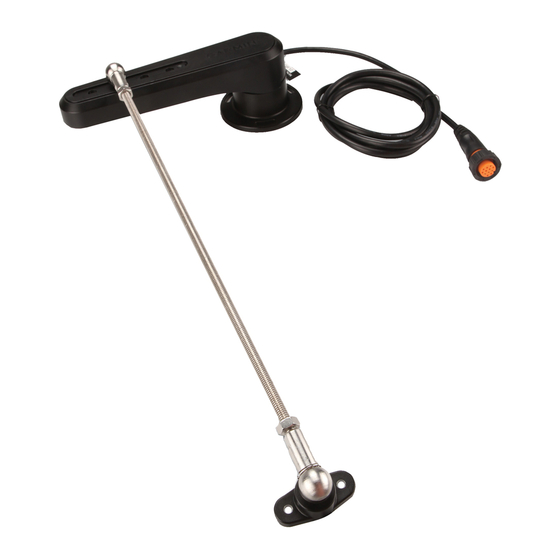
GRF™ 10 Installation Instructions
See the Important Safety and Product Information guide in the
product box for product warnings and other important
information.
Installation Preparation
Always wear safety goggles, ear protection, and a dust mask
when drilling, cutting, or sanding.
When drilling or cutting, always check what is on the opposite
side of the surface.
Package Contents
Item
Description
GRF™ 10
M4 screw (×5)
M6 locknut (×2)
M6 nut (×2)
Washer
Tiller arm mount
Ball joint assembly (×2)
Threaded rod
Tools Needed
1
• Drill and
/
in. (3.2 mm) drill bit
8
• 8 and 10 mm wrenches
• 10 mm socket
• Metal saw appropriate for cutting a threaded rod
• #2 Phillips screwdriver
• Tape measure
• Pencil or marker
• Extension cables, if necessary
WARNING
CAUTION
NOTICE
(page
2)
Mounting Considerations
The sensor must be installed parallel to the tiller arm while the
rudder is amidships.
The distance from the rotation axis of the tiller to the ball-joint
assembly must be the same as the distance from the rotation axis
of the sensor to the ball joint assembly.
The sensor and rudder rotation axes must be aligned.
The maximum range of travel from stop to stop is 140° (70º from
the center position to each stop). Exceeding this range may result
in damage to the sensor.
The rod that connects the sensor to the tiller arm is 11.8 in. (300
mm) long, and can be shortened if needed.
The rod should be level when connected to the sensor and rudder.
If a perfectly level installation is not possible, the rod must be
installed within +/- 5º off level in order to function correctly.
The rod should be installed perpendicular to the tiller arm and
sensor, using the second hole from the tip of the sensor for the ball-
joint connector.
Although the second hole is preferred, the other holes may be used
if necessary for the installation location.
Connection Considerations
• This sensor can be connected to a compatible Garmin
autopilot system with a 12-pin rudder feedback connector.
• The cable connected to the sensor is 78 in. (2 m) long.
◦ If needed, extension cables for the sensor are available
from your Garmin dealer.
◦ Do not cut the sensor cable to extend or shorten it.
Installation Procedures
Installing the Sensor
For the best results, keep the rudder amidships during the
sensor-installation process.
1
Rotate the sensor counter-clockwise so the arrows on the
back
line up in the center
holes.
®
before marking the mounting
Advertisement

Related Manuals for Garmin GRF 10


Summary of Contents for Garmin GRF 10
-
Page 1: Package Contents
M6 nut (×2) if necessary for the installation location. Washer Connection Considerations Tiller arm mount • This sensor can be connected to a compatible Garmin ® Ball joint assembly (×2) autopilot system with a 12-pin rudder feedback connector. Threaded rod •... -
Page 2: Specifications
Connect the sensor to the autopilot system. Configuring the Sensor When connected to a Garmin autopilot system, the sensor is configured using the autopilot helm control. NOTE: If an error appears during these steps, the sensor may have reached the limit of its movement range. Make sure the sensor was installed correctly.