Table of Contents
Advertisement
Quick Links
Advertisement
Table of Contents

Related Manuals for Garmin GMA 240


Summary of Contents for Garmin GMA 240
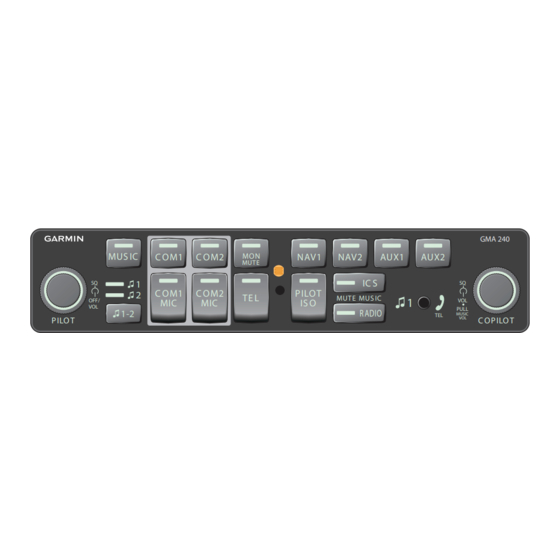
- Page 1 GMA 240 Installation Manual GMA 240 MUS IC C OM1 C OM2 NAV1 NAV2 AUX1 AUX2 MUTE IC S C OM1 C OM2 P ILOT TE L MUTE MUS IC OFF/ IS O PULL R ADIO MUSIC P ILO T...
- Page 2 Garmin. Garmin hereby grants permission to download a single copy of this manual and of any revision to this manual onto a hard drive or other electronic...
- Page 3 Section 1 1-1 – 1-4 Section 2 2-1 – 2-6 Section 3 3-1 – 3-4 Section 4 4-1 – 4-10 Appendix A A-1 – A-3 Appendix B B-1 – B-4 Appendix C 190-00917-01 GMA 240 Installation Manual Rev. D Page i...
- Page 4 The table is current at the time of publication of this manual (see date on front cover) and is subject to change without notice. Authorized Garmin Sales and Service Centers are encouraged to access the most up-to-date bulletin and advisory information on the Garmin Dealer Resource web site at www.garmin.com using their Garmin-provided user name and password.
- Page 5 (iv) damage caused by service performed by anyone who is not an authorized service provider of Garmin; or (v) damage to a product that has been modified or altered without the written permission of Garmin. In addition, Garmin reserves the right to refuse warranty claims against products or services that are obtained and/or used in contravention of the laws of any country.
- Page 6 This page intentionally left blank GMA 240 Installation Manual 190-00917-01 Page iv Rev. D...
-
Page 7: Table Of Contents
1.4 Reference Documents ...................... 1-4 Section 2 INSTALLATION OVERVIEW............2-1 2.1 Introduction........................2-1 2.2 Installation Materials ....................... 2-1 2.3 GMA 240 Wiring, Configuration, and Adjustment Options ........... 2-1 2.4 Noise ..........................2-5 2.5 GMA 240 Mounting ......................2-6 Section 3 INSTALLATION PROCEDURE .............3-1 3.1 Unpacking Unit........................ - Page 8 Figure A-3 GMA 240 Recommended Panel Cutout Dimensions........A-3 Appendix B Interconnect Drawings ..............B-1 Figure B-1 GMA 240 Interconnect Drawing (page 1 of 3) ..........B-1 Figure B-1 GMA 240 Interconnect Drawing (page 2 of 3) ..........B-2 Figure B-1 GMA 240 Interconnect Drawing (page 3 of 3) ..........B-3 Figure B-2 GMA 240, J2401 &...
- Page 9 Table 4-12 Failsafe Warning Audio ..................4-8 Table 4-13 Music Inputs ....................... 4-8 Table 4-14 Tel Audio I/O ..................... 4-8 Table 4-15 Headset Outputs ....................4-9 Table 4-16 COM Swap ....................... 4-10 190-00917-01 GMA 240 Installation Manual Rev. D Page vii...
- Page 10 This page intentionally left blank GMA 240 Installation Manual 190-00917-01 Page viii Rev. D...
-
Page 11: Section 1 General Description
GMA 240 throughout this manual refers to all versions of the unit. Information pertaining to the maintenance of the unit can be found in the GMA 240 Maintenance Manual, P/N 190-00917-02. Information pertaining to the operation of the unit can be found in the GMA 240 Pilot's Guide, P/N 190-00917-00. -
Page 12: Technical Specifications
Depth Behind Panel with Connectors (measured from face of aircraft 7.12 inches (181 mm) panel to rear of connector backshells) GMA 240 Weight (Unit Only) 15.5 oz (440 g) GMA 240 Weight (Installed with rack and connectors) 24 oz (680 g) GMA 240 Installation Manual 190-00917-01 Page 1-2... -
Page 13: Table 1-2 Electrical Characteristics
150 Ω 100 mW <0.07% THD+N Outputs 50 Ω 150 mW <0.07% THD+N 50 Ω 300 mW <0.10% THD+N Compatible with higher headphone impedances, those shown are for worst-case distortion and bandwidth 190-00917-01 GMA 240 Installation Manual Rev. D Page 1-3... -
Page 14: Reference Documents
7.5 W max. operation (540 mA @ 13.8 V) 1.4 Reference Documents The following publications are sources of additional information for installing the GMA 240. Before installing the unit, the technician should read all referenced materials along with this manual. -
Page 15: Section 2 Installation Overview
2 INSTALLATION OVERVIEW 2.1 Introduction This section provides the necessary information for the installation and checkout of the GMA 240 Audio Panel. Installation of the GMA 240 will differ according to equipment location and other factors. Cabling will be fabricated by the installing agency to fit these various requirements. The appendices contain interconnect wiring diagrams, mounting dimensions, and information pertaining to installation. -
Page 16: Figure 2-1 Esd Caution Logo
PCB. The jumper positions are designed to accept a 0Ω resistor of 0603 size. Refer to Appendix C component location. This service should only be performed by a qualified technician. Garmin is not responsible for damage caused during adjustment of these internal configuration jumper settings. Refer to the GMA 240 Maintenance Manual for disassembly/reassembly instructions. - Page 17 Empty Reserved R0300 Reserved Empty Reserved 2.3.2 VOLUME/MUTE Configuration Adjustments The following adjustments can be made through access holes in the top cover of the GMA 240: • Alert 1 Volume • Alert 2 Volume • Alert 3 Volume •...
-
Page 18: Figure 2-2 Access Hole Locations (Top View)
Normally, the isolated ICS positions do not hear music. BUTTON PRESS TONE ENABLE: This input enables an audible tone to be heard when a button press is GMA 240 Installation Manual 190-00917-01 Page 2-4... -
Page 19: Noise
Good aircraft electrical/charging system ground bonding is also important. The wiring diagrams and accompanying notes in this manual should be followed closely to minimize noise effects. 190-00917-01 GMA 240 Installation Manual Rev. D Page 2-5... -
Page 20: Gma 240 Mounting
The GMA 240 mounting surface must be capable of providing structural support and electrical bond to the aircraft to minimize radiated EMI and provide protection from High-Intensity Radiation Fields (HIRF). The GMA 240 is mounted using a GMA 340 unit rack. Figure 2-3 shows the GMA 340 unit rack. See Section 3.4 for installation instructions. -
Page 21: Section 3 Installation Procedure
If the unit is damaged, notify the carrier and file a claim. To justify a claim, save the original shipping container and all packing materials. Do not return the unit to Garmin until the carrier has authorized the claim. -
Page 22: Audio Shield Termination
CAUTION Do not use excessive force when inserting the GMA 240 into the rack. This may damage the connectors, unit, and/or unit rack. If heavy resistance is felt during installation, stop, and remove the GMA 240 and identify the source of resistance. -
Page 23: Post Installation Checkout
Post Installation Checkout CAUTION Check wiring connections for errors before inserting the GMA 240 into the rack. Incorrect wiring could cause internal component damage. An in-aircraft checkout may be performed in the aircraft on the ramp with known good microphone, headset, and avionics receivers. -
Page 24: Configuration Adjustments
This completes the in-aircraft post installation checkout. Perform a flight test after installing the unit to ensure satisfactory performance of the audio functions. 3.6 Configuration Adjustments Adjustment to the Volume and Squelch settings can be made to the GMA 240 through access holes in the unit's top cover. Refer to Section 2.3 for details. -
Page 25: Section 4 System Interconnects
4 SYSTEM INTERCONNECTS 4.1 Connector Description The GMA 240 has two 44-pin connectors located at the rear of the unit designated J2401 and J2402 which are oriented as shown in Figure 4-1. J2402 J2401 Figure 4-1 Rear View of Backplate and Rack 4.2 Pin List... - Page 26 PASS HEADSET AUDIO OUT RIGHT PASS HEADSET AUDIO OUT LO ALERT 2,3 AUDIO IN LO ALERT 2 AUDIO IN HI *Denotes Active Low (Inputs: ground to activate; Outputs: grounded when active) GMA 240 Installation Manual 190-00917-01 Page 4-2 Rev. D...
-
Page 27: Table 4-2 J2402 Pin Assignments
COPILOT MIC AUDIO IN HI COPILOT MIC KEY* IN COPILOT MIC AUDIO IN LO PASS 1 MIC AUDIO IN HI *Denotes Active Low (Inputs: ground to activate; Outputs: grounded when active) 190-00917-01 GMA 240 Installation Manual Rev. D Page 4-3... -
Page 28: Aircraft Power And Lighting
MUSIC 1 RIGHT IN/TEL AUDIO IN HI SLEEVE MUSIC 1 LO IN/TEL AUDIO LO 4.3 Aircraft Power and Lighting 4.3.1 Aircraft Power The GMA 240 has four inputs for aircraft power bus inputs of 14/28Vdc. Table 4-4 Aircraft Power Connector Pin Name P2402 AIRCRAFT POWER... -
Page 29: Configuration Pins
4.3.2 Lighting Bus The GMA 240 can be configured to track a 14 or 28 Vdc lighting bus using these inputs. These inputs must be connected to a supply voltage (in the appropriate voltage range) for the backlighting to function. -
Page 30: Audio Inputs/Outputs And Mic Keys
P2402 PILOT ICS KEY* IN Enables respective mic audio to be heard in the P2401 COPILOT ICS KEY* IN intercom P2401 PASSENGER ICS KEY* IN *Denotes Active Low (Ground to activate) GMA 240 Installation Manual 190-00917-01 Page 4-6 Rev. D... -
Page 31: Table 4-9 Com Audion And Mic Keys
NAV 1 Audio Input P2401 NAV 1 AUDIO IN LO NAV 1 Ground Reference P2401 NAV 2 AUDIO IN HI NAV 2 Audio Input P2401 NAV 2 AUDIO IN LO NAV 2 Ground Reference 190-00917-01 GMA 240 Installation Manual Rev. D Page 4-7... -
Page 32: Table 4-12 Failsafe Warning Audio
Table 4-14 Tel Audio I/O Connector Pin Name Description P2401 TEL AUDIO IN HI Telephone Audio Input P2401 TEL AUDIO LO Ground Reference for Telephone P2401 TEL MIC AUDIO OUT HI TEL MIC Audio Output GMA 240 Installation Manual 190-00917-01 Page 4-8 Rev. D... -
Page 33: Table 4-15 Headset Outputs
NOTE Using a mono headset with an audio jack wired for stereo may damage the GMA 240. Installations using only mono headsets may use a stereo audio jack and leave the ring contact unconnected or install a switch as shown in Figure 4-4. Also note that many stereo headsets have a mono/stereo switch to be compatible with mono or stereo-wired jacks. -
Page 34: Figure 4-4 Audio Jack Wiring
Pin Name Description Ground Through a Momentary PB P2402 COM SWAP* IN Switch to Swap Active COM (COM 1 or COM 2) P2402 COM SWAP RETURN Return Path for PB Switch GMA 240 Installation Manual 190-00917-01 Page 4-10 Rev. D... -
Page 35: Appendix A Outline And Installation Drawings
APPENDIX A Outline and Installation Drawings J2401 J2402 Figure A-1 GMA 240 Outline Drawing 190-00917-01 GMA 240 Installation Manual Revision D Page A-1... -
Page 36: Figure A-2 Gma 240 Connector/Rack Assembly Drawing
APPENDIX A Outline and Installation Drawings J2401 J2402 Figure A-2 GMA 240 Connector/Rack Assembly Drawing 190-00917-01 GMA 240 Installation Manual Revision D Page A-2... -
Page 37: Figure A-3 Gma 240 Recommended Panel Cutout Dimensions
APPENDIX A Outline and Installation Drawings Figure A-3 GMA 240 Recommended Panel Cutout Dimensions 190-00917-01 GMA 240 Installation Manual Revision D Page A-3... -
Page 38: Appendix B Interconnect Drawings
APPENDIX B Interconnect Drawings Figure B-1 GMA 240 Interconnect Drawing (page 1 of 3) 190-00917-01 GMA 240 Installation Manual Revision D Page B-1... -
Page 39: Figure B-1 Gma 240 Interconnect Drawing (Page 2
APPENDIX B Interconnect Drawings Figure B-1 GMA 240 Interconnect Drawing (page 2 of 3) 190-00917-01 GMA 240 Installation Manual Revision D Page B-2... -
Page 40: Figure B-1 Gma 240 Interconnect Drawing (Page 3
APPENDIX B Interconnect Drawings 10. IF PINS 5, 6, & 7 ARE NOT CONNECTED IN THE 14V OR 28V CONFIGURATION, BACKLIGHTING WILL NOT FUNCTION (NO BACKLIGHTING). Figure B-1 GMA 240 Interconnect Drawing (page 3 of 3) 190-00917-01 GMA 240 Installation Manual... -
Page 41: Figure B-2 Gma 240, J2401 & J2402 Connector Layout Drawing
AUDIO IN HI HEADSET AUDIO IN LO AUDIO IN HI AUDIO IN LO KEY* IN AUDIO IN HI AUDIO OUT RIGHT Figure B-2 GMA 240, J2401 & J2402 Connector Layout Drawing 190-00917-01 GMA 240 Installation Manual Revision D Page B-4... -
Page 42: Appendix C Configuration Jumpers Drawing
APPENDIX C Configuration Jumpers Drawing Top of Main Board Bottom of Main Board Figure C-1 GMA 240 Internal ConfigurationJumper Layout Drawing 190-00917-01 GMA 240 Installation Manual Revision D Page C-1...