Advertisement
Quick Links
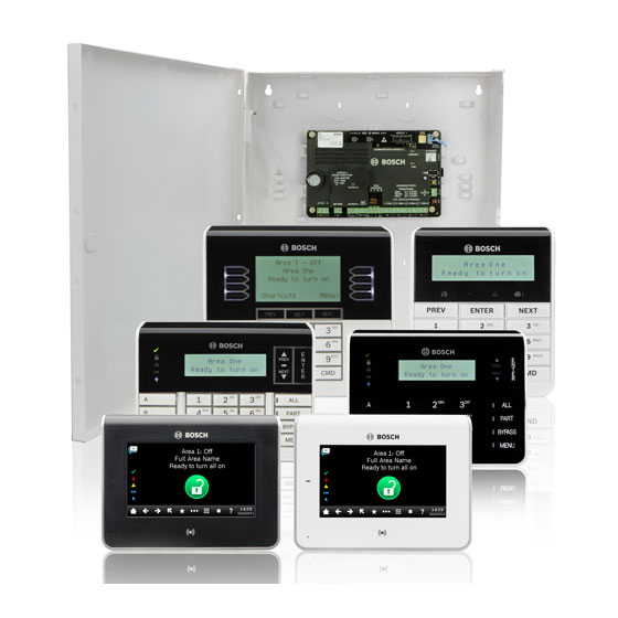
B Series Control Panel
Installer Quick Start Guide
Use this guide to quickly install a Bosch B6512/B5512/B4512/B3512 security system. Additional information is found in the Control Panels Installation Manual.
When you see this icon, use your smart phone with
a QR code reader app to view helpful videos.
For additional training:
Bosch YouTube channel:
B Series Installer's Site:
1. Scan QR code.
2. Scroll down.
3. Locate and select your region
(North America only)
for additional videos.
Installation
sequence:
Scan and follow these
videos in sequential order
to the steps listed below.
Step 1
Mounting the control panel
Bosch tips:
▶ Mount the enclosure prior to mounting the control panel.
▶ Mount control panel into enclosure with hardware provided.
B10
Step 4
Installing expansion modules
Bosch tips:
▶ If installing more than one device that is similar, refer to the
module's installation guide for address settings (for example,
two of the same device).
▶ If installing a RADION B810 wireless receiver, use address 1 only.
7 COM 8
C
COM AUX
R
Y
G
B
1
C
O
M
2
3
COM
4
5
COM
6
7
C
O
M
8
A
PWR A
B COM
R
R
Y
Y
G
G
B
B
Step 7
Powering the control panel
Bosch tips:
▶ Connect wires to control panel before applying battery or AC
power.
▶ Connect earth ground to a cold water pipe (copper) or other
solid connection to ground.
18VAC
+ BAT -
NO C NC
COM AUX
R
Y
G
B
1
C
O
M
2
3
OUTPUT A
PWR A
B COM
Control panel component layout
M
L
K
Step 2
M
Bosch tips:
▶ Insert leg of module into slot marked "x."
▶ Cellular: Place antenna on top of enclosure and run cable inside,
then connect to module.
▶ PSTN: Connect module to a D166 (RJ31x) jack using a D161/D162
cable.
B11
Step 5
I
Bosch tips:
▶ If using a dual EOL, 2K EOL, or no EOL, refer to control panel
installation guide for control panel settings.
▶ If using 2-wired powered devices, use a B201 or D125B.
C
COM AUX
R
Y
G
A
PWR A
B COM
k
Step 8
L
Bosch tips:
▶ If configuring using the Installer Services Portal, go to Step 11.
▶ Install Remote Programming Software (RPS) v6.06 or later. You can
download RPS from the RPS product page.
▶ Follow the RPS Account Assistant instructions to create new control
panel accounts. The Account Assistant helps you create a new panel
account.
▶ If RPS is not available, keypad programming is an option. Refer to
keypad installation instructions.
7 COM 8
COM
4
5
COM
6
7
C
O
M
8
A
B
C
D
E
F
G
J
I
H
Installing a communication module
Installing wired inputs
NOTE: Not all
modules are available
in all regions.
7 COM 8
B
1
C
O
M
2
3
COM
4
5
COM
6
7
C
O
M
8
NC
NO
EOL
Create panel accounts using RPS
Control panel connection location
Location
Item
Description
Specification
Plug-in comm
A
MODULE 1
Communication module options
module
B
ETHERNET
Ethernet port
built-in on-board Ethernet connection (10Base-T/100Base-T)
C
USB
USB port
USB connector (for firmware updates and RPS connection)
D
Heartbeat LED
Slow=normal, rapid=service mode
E
Reset
Reset switch
Hold five seconds to enter or exit service mode
F
B C
Outputs B(2) C(3)
Open collector, 50mA, active low
G
TMPR
Tamper
Optional tamper switch connector (ICP-EZTS)
1 COM 2 to
H
Alarm inputs
End Of Line (EOL) resistor supervised alarm inputs
7 COM 8
I
R Y G B
SDI2 bus
SDI2 device bus
J
COM AUX
Aux power
12 VDC, 800mA
K
NO C NC
Output A(1)
Programmable relay output
+ BAT –
Battery, Earth
L
Primary/Secondary power and Earth Ground connections
18 VAC,
ground, 18 VAC
M
Mounting
Mounting holes
Mounting holes for control panel
Step 3
A
Installing a keypad
Bosch tips:
▶ When installing a compatible Bosch keypad, refer to keypad
installation guide for specific wiring diagrams. Basic keypad wiring
is shown below.
▶ When installing more than one keypad, refer to keypad
installation guide for unique address settings.
7 COM 8
C
COM AUX
R
Y
G
B
1
C
O
M
2
3
COM
4
5
COM
6
7
C
O
M
A
PWR A
B COM
Step 6
H
Installing a bell or siren
Bosch tips:
▶ Output A can supply up to 1 A at 12 VDC when sourced from a
control panel (jumper in AUX PWR position).
▶ Output A can support up to 3 amps at 12 VDC when using a
separate power supply (jumper in DRY position).
▶ Output B and C are open collectors and are limited to 50 mA at
12 VDC.
+
Step 9
Connecting the control panel using RPS
Bosch tips:
▶ Connect a computer with RPS installed. Direct RPS connections
can be done through a USB connection or Ethernet connection.
▶ The Account Assistant automatically launches when you create a
new account.
▶ For USB direct connection, use a B99 USB cable.
I
8
J
K
B
C
Advertisement

Related Manuals for Bosch B Series


Summary of Contents for Bosch B Series
- Page 1 B Series Control Panel Installer Quick Start Guide Use this guide to quickly install a Bosch B6512/B5512/B4512/B3512 security system. Additional information is found in the Control Panels Installation Manual. Control panel component layout Control panel connection location When you see this icon, use your smart phone with a QR code reader app to view helpful videos.
- Page 2 Step 12 Test the system Note: Not all products and features are available in all regions. Consult your Bosch representative or product datasheets for details. After system installation and control panel programming, you must perform a complete system test. A complete system test...