
Related Manuals for Rheem 64DV


Summary of Contents for Rheem 64DV
- Page 1 TANKLESS GAS TR UBLESHOOTING POCKET MANUAL SVC 820P For Mid & High Efficiency Platforms EV 0 P REV 0 Rheem.com...
- Page 2 S V C 8 2 0 ( P ) P o c k e t M a n u a l P a g e This manual is specific to the following model numbers: MID EFFICIENCY 64DV, 64X / 68DV / 68X 84DV, 84X / 95DV, 95X 150DV, 150X / 180DV, 180X / 200DV, 200X...
-
Page 3: Table Of Contents
P a g e S V C 8 2 0 ( P ) P o c k e t M a n u a l TABLE OF CONTENTS General Information Installation Guidelines……………………………………………….. 8 Mid & High-Efficiency Flow Rates…………………………….. 12 Control Board Connectors………………………………………… 14 Diagnostic Points (Voltage &... - Page 4 S V C 8 2 0 ( P ) P o c k e t M a n u a l P a g e 61 Error Code 65 Error Code 66 Error Code 71 Error Code 72 Error Code 76 Error Code 79 Error Code 80 Error Code...
- Page 5 P a g e S V C 8 2 0 ( P ) P o c k e t M a n u a l Important Safety Information READ the Safety Information Before inspecting, diagnosing, repairing or operating any water heater, be sure to examine all of the safety and warning labels on the water heater.
- Page 6 S V C 8 2 0 ( P ) P o c k e t M a n u a l P a g e liquids (adhesives, solvents, etc.), and vapors they produce are extremely dangerous. DO NOT handle, use or store gasoline or other flammable or combustible materials anywhere near or in the vicinity of a water heater.
- Page 7 P a g e S V C 8 2 0 ( P ) P o c k e t M a n u a l Troubleshooting Tools Multi-Meter Used to measure Resistance & Voltage Multi-Meter Needle Set Used on meter test leads to access connectors...
- Page 8 S V C 8 2 0 ( P ) P o c k e t M a n u a l P a g e MEASURING VOLTAGE & RESISTANCE WARNING: , DO NOT cross/touch HILE MEASURING VOLTAGE multi-meter leads together. This will cause damage to electrical components.
-
Page 9: Installation Guidelines
P a g e S V C 8 2 0 ( P ) P o c k e t M a n u a l Installation Guidelines for HIGH-Efficiency ONLY: GAS TYPE: Liquid Propane (LP) or Natural (NG) NG MAX INLET GAS PRESSURE: 10.5 (In. of w.c.) NG MIN INLET GAS PRESSURE: 4.0 (In. - Page 10 S V C 8 2 0 ( P ) P o c k e t M a n u a l P a g e Installation Guidelines for HIGH-Efficiency ONLY: The vent exhaust and air intake must be vented outside as described in the use and care manual.
- Page 11 10 | P a g e S V C 8 2 0 ( P ) P o c k e t M a n u a l Installation Guidelines for MID-Efficiency ONLY: GAS TYPE: Liquid Propane (LP) or Natural (NG) NG MAX INLET GAS PRESSURE: 10.5 (In.
- Page 12 S V C 8 2 0 ( P ) P o c k e t M a n u a l P a g e Installation Guidelines for MID-Efficiency ONLY: WARNING: Use 3-in. /5-in. UL-approved Category III Stainless Steel vent materials or water heater manufacturer-approved vent material.
-
Page 13: Mid & High-Efficiency Flow Rates
P a g e S V C 8 2 0 ( P ) P o c k e t M a n u a l MID-EFFICIENCY FLOW RATES 64DV & 64X Temperature Rise ( ° F) Max Water Flow - GPM (gallons per minute) 68DV &... - Page 14 S V C 8 2 0 ( P ) P o c k e t M a n u a l P a g e HIGH-EFFICIENCY FLOW RATES (Condensing) H84DV & H84X Temperature Rise ( ° F) Max Water Flow - GPM (gallons per minute) H95DV &...
-
Page 15: Control Board Connectors
14 | P a g e S V C 8 2 0 ( P ) P o c k e t M a n u a l Control Board Connectors Fuel Type Chip ***FUEL TYPE CHIP*** – When replacing Control Board, you must use the original chip on the new Control Board. - Page 16 S V C 8 2 0 ( P ) P o c k e t M a n u a l P a g e CONTROL BOARD CONNECTORS POWER...
-
Page 17: Diagnostic Points (Voltage & Resistance Readings)
16 | P a g e S V C 8 2 0 ( P ) P o c k e t M a n u a l Diagnostic Points on Control Board What are Wire Connection Normal Value Color checking? Do you have power to the I –... - Page 18 S V C 8 2 0 ( P ) P o c k e t M a n u a l P a g e What are Connection Wire Color Normal Value checking? Does the fan motor BK4-R6 DC 144-192V have the proper voltage?
- Page 19 18 | P a g e S V C 8 2 0 ( P ) P o c k e t M a n u a l What are Connection Wire Color Normal Value checking? 68°F=10.3KΩ Is the water outlet R4-BK3 thermistor 104°F=4.9KΩ...
- Page 20 S V C 8 2 0 ( P ) P o c k e t M a n u a l P a g e What are Wire Connection Normal Value Color checking? Is the P.G.F.R. valve operating? DC1.5-14V (Proportional R1-BK2 40Ω-80Ω...
- Page 21 20 | P a g e S V C 8 2 0 ( P ) P o c k e t M a n u a l What are Wire Connection Normal Value Color checking? Gas inlet DC 90-120 V Y1-BK6 solenoid 0.8KΩ-2.4KΩ...
-
Page 22: Maintenance Mode Instructions
S V C 8 2 0 ( P ) P o c k e t M a n u a l P a g e Maintenance Mode Panel Display INSTRUCTIONS The Rheem/Ruud Tankless has a maintenance mode chart on the remote control. To access the maintenance mode, turn the unit OFF at remote control and make sure water flow is OFF. - Page 23 22 | P a g e S V C 8 2 0 ( P ) P o c k e t M a n u a l You will see the following as you navigate the Y table in maintenance mode: = Flame rod status = Water flow in gallons per minute = Ambient air temperature...
- Page 24 S V C 8 2 0 ( P ) P o c k e t M a n u a l P a g e...
- Page 25 24 | P a g e S V C 8 2 0 ( P ) P o c k e t M a n u a l NOTES: _________________________ _________________________ _________________________ _________________________ _________________________ _________________________ _________________________ _________________________ _________________________ _________________________ _________________________ _________________________ _________________________ _________________________...
-
Page 26: Altitude Settings On Control Board
S V C 8 2 0 ( P ) P o c k e t M a n u a l P a g e Altitude Settings on Control Board Locate the two DIP switches at top right of Control Board. Switch labeled DIP2 is the bottom switch. -
Page 27: Reset Procedures
26 | P a g e S V C 8 2 0 ( P ) P o c k e t M a n u a l RESET PROCEDURE ONLY for ‘Hard Lockouts’ - Error Codes: 10, 13 & 99 1. -
Page 28: Clearing Fault History
S V C 8 2 0 ( P ) P o c k e t M a n u a l P a g e CLEARING FAULT HISTORY PROCEDURE 1. Turn remote control OFF; leave unit plugged in. Remove front cover. Locate the DIP Switches (Upper Right on the control board). -
Page 29: No Error Code & No Hot Water
28 | P a g e S V C 8 2 0 ( P ) P o c k e t M a n u a l No Error Code & No Hot Water Explanation: No hot water is delivered when water is flowing through unit and remote control displays the hot water temperature setting. - Page 30 S V C 8 2 0 ( P ) P o c k e t M a n u a l P a g e Single Unit Installations ONLY: All DIP1 switches must be in the ‘OFF’ position (DOWN). Manifold (Multiple) Unit Installations ONLY: Go to 03 - Error Code to verify proper DIP1 setting.
- Page 31 30 | P a g e S V C 8 2 0 ( P ) P o c k e t M a n u a l NOTES: _________________________ _________________________ _________________________ _________________________ _________________________ _________________________ _________________________ _________________________ _________________________ _________________________ _________________________ _________________________ _________________________ _________________________...
-
Page 32: P1 Warning Code
S V C 8 2 0 ( P ) P o c k e t M a n u a l P a g e P1 - Warning Code Explanation: No hot water is delivered when water is flowing through unit and remote control displays P1 - Warning Code. -
Page 33: Warning Code
Cold Water (hot water side) Service Valve (cold water side) Drain Hose (hot water side) Drain Hose (cold water side) 5-Gallon Bucket Utility Pump NOTE: Flushing instructions utilize a submersible utility pump (provided with the Rheem/Ruud Tankless Flush Kit – RTG20124) - Page 34 S V C 8 2 0 ( P ) P o c k e t M a n u a l P a g e Turn OFF gas and both the cold and hot water supply to the water heater. The gas must remain OFF during the flushing process.
-
Page 35: Error Code
34 | P a g e S V C 8 2 0 ( P ) P o c k e t M a n u a l 03 - Error Code Only for manifold (multiple) unit installations: Link; MIC-6; or MIC-185 manifold controllers. Explanation: Communication failure between water heaters, remote control, and/or manifold controller. -
Page 36: Warning Code
S V C 8 2 0 ( P ) P o c k e t M a n u a l P a g e 05 – Warning Code Explanation: The flame rod has detected improper burner combustion (Indoor Units ONLY). This warning code is commonly caused by VENTING and/or GAS SUPPLY. - Page 37 36 | P a g e S V C 8 2 0 ( P ) P o c k e t M a n u a l NOTES: _________________________ _________________________ _________________________ _________________________ _________________________ _________________________ _________________________ _________________________ _________________________ _________________________ _________________________ _________________________ _________________________ _________________________...
-
Page 38: Warning Code
S V C 8 2 0 ( P ) P o c k e t M a n u a l P a g e 10 – Warning Code Explanation: Unit was operated prior to vent installation OR blower motor is not creating enough ventilation. - Page 39 38 | P a g e S V C 8 2 0 ( P ) P o c k e t M a n u a l Blower Motor Diagnostics: INDOOR Models ONLY Test DC voltage across Remove & reinsert G . Black and Red wires Operate unit again.
- Page 40 S V C 8 2 0 ( P ) P o c k e t M a n u a l P a g e Blower Motor Diagnostics: OUTDOOR Models ONLY Test DC voltage across Remove & reinsert G . Blue and White wires Operate unit again.
-
Page 41: Error Code
40 | P a g e S V C 8 2 0 ( P ) P o c k e t M a n u a l 11 – Error Code Explanation: Flame rod(s) does not detect flame. Commonly GAS SUPPLY and/or VENTING. Diagnostic Checks: ... - Page 42 S V C 8 2 0 ( P ) P o c k e t M a n u a l P a g e Igniter Rod Diagnostics (spark is NOT visible) While attempting to ignite, Remove & reinsert H . test AC Volts across 2 Grey Operate unit again.
- Page 43 42 | P a g e S V C 8 2 0 ( P ) P o c k e t M a n u a l Flame Rod Diagnostics (flame IS visible) Turn Power OFF. Remove and reinsert connector M , T , and terminal on flame rod(s).
- Page 44 S V C 8 2 0 ( P ) P o c k e t M a n u a l P a g e Flame Rod(s) Diagnostics Remove & reinsert M . Test AC volts on Operate unit again. connector M (Grey wire to Ground) IF code 11 appears:...
- Page 45 44 | P a g e S V C 8 2 0 ( P ) P o c k e t M a n u a l Gas Control Valve Diagnostics (Igniter Rod Sparks & NO flame) IMPORTANT: DURING VOLTAGE CHECKS – CONNECTOR K ONLY (water is flowing and unit is attempting to ignite): IF you do NOT get a voltage reading, push and hold the MAX button on upper right hand corner of control board to activate unit at full BTU s.
- Page 46 S V C 8 2 0 ( P ) P o c k e t M a n u a l P a g e Gas Control Valve Diagnostics Remove & reinsert R . While attempting to ignite test DC volts across #1 wire Operate unit again.
-
Page 47: Error Code
46 | P a g e S V C 8 2 0 ( P ) P o c k e t M a n u a l 12 – Error Code Explanation: Commonly GAS SUPPLY and/or VENTING. Unit detected the presence of flame and then lost it. - Page 48 S V C 8 2 0 ( P ) P o c k e t M a n u a l P a g e Remove & reinsert M . Test AC volts on Operate unit again. connector M (Grey wire to Ground) IF code 12 appears: 1 –...
-
Page 49: Error Code
48 | P a g e S V C 8 2 0 ( P ) P o c k e t M a n u a l 13 – Error Code Explanation: Indoor units ONLY. Flame rod is detecting poor combustion. This is commonly caused by inadequate GAS SUPPLY and/or VENTING. - Page 50 S V C 8 2 0 ( P ) P o c k e t M a n u a l P a g e Remove & reinsert T . Test AC volts on Operate unit again. connector T (Blue wire to Ground) IF code 13 appears: 1 –...
-
Page 51: Error Code
50 | P a g e S V C 8 2 0 ( P ) P o c k e t M a n u a l 14 – Error Code Explanation: OHL (Over Heat Limiter) or Over Temp Limit Switch activated. - Page 52 S V C 8 2 0 ( P ) P o c k e t M a n u a l P a g e Mid Efficiency ONLY: Replace Unit. Turn power OFF. Remove connector U . Measure resistance across both White High Efficiency wires: Indoor ONLY:...
-
Page 53: Error Code
52 | P a g e S V C 8 2 0 ( P ) P o c k e t M a n u a l 15 – Error Code Explanation: The hot water temperature and/or heat exchanger temperature reached 207 degrees F for more than 15 seconds. -
Page 54: Error Code
S V C 8 2 0 ( P ) P o c k e t M a n u a l P a g e 16 – Error Code Explanation: Outlet water temperature is above the set point on the remote control. Diagnostic Checks: ... -
Page 55: Error Code
54 | P a g e S V C 8 2 0 ( P ) P o c k e t M a n u a l 24 – Error Code Explanation: Remote control buttons were depressed for more than 20 seconds, release buttons and operate unit. -
Page 56: Error Code
S V C 8 2 0 ( P ) P o c k e t M a n u a l P a g e 29 – Error Code (A) Explanation: High-Efficiency (condensing) Units ONLY: Condensation is NOT draining. Diagnostic Checks: ... -
Page 57: Mid & High-Efficiency (B)
56 | P a g e S V C 8 2 0 ( P ) P o c k e t M a n u a l 29 – Error Code (B) Explanation: Heat exchanger temperature too low for more than 3 minutes. Diagnostic Checks: ... - Page 58 S V C 8 2 0 ( P ) P o c k e t M a n u a l P a g e Calculate Temperature Rise & Gallons per Minute: 1. Enter maintenance mode & select table 3Y. Turn on water flow to determine inlet water temperature.
-
Page 59: Error Code
58 | P a g e S V C 8 2 0 ( P ) P o c k e t M a n u a l 31 – Error Code Explanation: Inlet thermistor malfunction. Diagnostic Checks: Inlet thermistor Turn Power OFF. - Page 60 S V C 8 2 0 ( P ) P o c k e t M a n u a l P a g e Locate & separate WHITE Clean scale build-up on inlet Molex (located near blower thermistor. Operate unit. IF motor).
-
Page 61: Error Code
60 | P a g e S V C 8 2 0 ( P ) P o c k e t M a n u a l 32 – Error Code Explanation: Heat exchanger thermistor malfunction. Diagnostic Checks: Heat exchanger thermistor Turn Power OFF. - Page 62 S V C 8 2 0 ( P ) P o c k e t M a n u a l P a g e Clean scale build-up on heat Locate & separate Yellow or exchanger thermistor. Green Molex (located near Reassemble and operate blower motor).
-
Page 63: Error Code
62 | P a g e S V C 8 2 0 ( P ) P o c k e t M a n u a l 33 – Error Code Explanation: Outlet thermistor malfunction. Diagnostic Checks: Outlet thermistor Turn Power OFF. - Page 64 S V C 8 2 0 ( P ) P o c k e t M a n u a l P a g e Clean scale build-up outlet Locate & separate Black thermistor. Reassemble and Molex (located near blower motor).
-
Page 65: Error Code
Turn Power OFF. Remove connector R : Measure resistance between #3 wire (Black) & #7 wire (Blue): 64DV; 84DV; 95DV: 7K – 23K Ohms 64X; 84X; 95X; H95X; H95DV: 2K – 72K Ohms Remove control board Reinsert connector R . - Page 66 S V C 8 2 0 ( P ) P o c k e t M a n u a l P a g e Locate & separate Blue Clean scale build-up ambient Molex (located near blower motor). Check resistance thermistor.
-
Page 67: Error Code
66 | P a g e S V C 8 2 0 ( P ) P o c k e t M a n u a l 35 – Error Code Explanation: Improper thermistor connection. Unit has four thermistors; one or more possibly has a poor connection or not connected in proper location. -
Page 68: Error Code
S V C 8 2 0 ( P ) P o c k e t M a n u a l P a g e 51 – Error Code Explanation: Gas control valve malfunction. Unit detected the presence of flame when demand for hot water terminated &... - Page 69 68 | P a g e S V C 8 2 0 ( P ) P o c k e t M a n u a l While viewing burner chamber through sight glass: Follow maintenance mode In 10 second intervals, cycle instructions at bottom of unit 3 times - page &...
- Page 70 S V C 8 2 0 ( P ) P o c k e t M a n u a l P a g e In 10 second intervals, cycle unit 3 times by turning unit: Follow maintenance mode ON-OFF; ON-OFF; ON-OFF instructions at bottom of page &...
-
Page 71: Error Code
70 | P a g e S V C 8 2 0 ( P ) P o c k e t M a n u a l 52 – Error Code Explanation: PGFR malfunction. The PGFR is the only modulating valve in the gas control valve. Diagnostics: PGFR (Proportional Gas Flow Regulator) Turn Power OFF. - Page 72 S V C 8 2 0 ( P ) P o c k e t M a n u a l P a g e While unit is attempting to Remove & reinsert R . ignite: Operate unit. Check DC volts across #1 wire (Red) and #2 wire If 52 –...
- Page 73 72 | P a g e S V C 8 2 0 ( P ) P o c k e t M a n u a l NOTES: _________________________ _________________________ _________________________ _________________________ _________________________ _________________________ _________________________ _________________________ _________________________ _________________________ _________________________ _________________________ _________________________ _________________________...
- Page 74 S V C 8 2 0 ( P ) P o c k e t M a n u a l P a g e 61 – Error Code Explanation: The Blower motor speed was not appropriate to allow proper combustion. Diagnostic Checks: ...
- Page 75 74 | P a g e S V C 8 2 0 ( P ) P o c k e t M a n u a l Blower Motor Diagnostics: Indoor Models ONLY Test DC voltage across Remove & reinsert G . Black and Red wires Operate unit again.
- Page 76 S V C 8 2 0 ( P ) P o c k e t M a n u a l P a g e Blower Motor Diagnostics: Outdoor Models ONLY Test DC voltage across Remove & reinsert G . Blue and White wires Operate unit again.
- Page 77 76 | P a g e S V C 8 2 0 ( P ) P o c k e t M a n u a l 65 – Error Code Explanation: Water volume control valve malfunction. Diagnostic Checks: Water volume control valve Turn Power Off, Remove &...
- Page 78 S V C 8 2 0 ( P ) P o c k e t M a n u a l P a g e While water is flowing & unit Check connector C . is attempting to ignite; check Operate unit again.
- Page 79 78 | P a g e S V C 8 2 0 ( P ) P o c k e t M a n u a l 66 – Error Code Explanation: Water by-pass valve malfunction. Connector Location Diagnostic Checks: On Page 14 ...
- Page 80 S V C 8 2 0 ( P ) P o c k e t M a n u a l P a g e 71 – Error Code Explanation: Gas control valve malfunction (inlet solenoid). Diagnostic Checks: Gas control valve Turn Power OFF.
- Page 81 80 | P a g e S V C 8 2 0 ( P ) P o c k e t M a n u a l NOTES: _________________________ _________________________ _________________________ _________________________ _________________________ _________________________ _________________________ _________________________ _________________________ _________________________ _________________________ _________________________ _________________________ _________________________...
- Page 82 S V C 8 2 0 ( P ) P o c k e t M a n u a l P a g e 72 – Error Code Explanation: Flame rod(s) malfunction. Flame rod(s) is detecting the presence of flame BEFORE igniter is activated.
- Page 83 82 | P a g e S V C 8 2 0 ( P ) P o c k e t M a n u a l Turn Power OFF. Unplug unit and plug back in. Turn Power ON. Follow maintenance mode instructions at bottom of While viewing through sight page &...
- Page 84 S V C 8 2 0 ( P ) P o c k e t M a n u a l P a g e Unit appears to be OK. Operate unit. Operate unit. Does 0Y status in maintenance mode indicate IF 72 –...
- Page 85 84 | P a g e S V C 8 2 0 ( P ) P o c k e t M a n u a l 76 – Error Code Explanation: Communication fault with remote control. Remote control is not communicating with control board.
- Page 86 S V C 8 2 0 ( P ) P o c k e t M a n u a l P a g e 79 – Error Code Explanation: Blower motor current fault. Diagnostic Checks: Blower motor Turn Power OFF. Remove control board bracket (How to Remove: Section 1).
- Page 87 86 | P a g e S V C 8 2 0 ( P ) P o c k e t M a n u a l Blower Motor Diagnostics: Indoor Models ONLY Test DC voltage across Remove & reinsert G . Black and Red wires Operate unit again.
- Page 88 S V C 8 2 0 ( P ) P o c k e t M a n u a l P a g e Blower Motor Diagnostics: Outdoor Models ONLY Test DC voltage across Remove & reinsert G . Blue and White wires Operate unit again.
- Page 89 88 | P a g e S V C 8 2 0 ( P ) P o c k e t M a n u a l NOTES: _________________________ _________________________ _________________________ _________________________ _________________________ _________________________ _________________________ _________________________ _________________________ _________________________ _________________________ _________________________ _________________________ _________________________...
- Page 90 S V C 8 2 0 ( P ) P o c k e t M a n u a l P a g e 80 – Error Code Explanation: Gas control valve malfunction. Unit detected the presence of flame when demand for hot water terminated &...
- Page 91 90 | P a g e S V C 8 2 0 ( P ) P o c k e t M a n u a l While viewing burner chamber through sight glass: Follow maintenance mode In 10 second intervals, cycle instructions at bottom of unit 3 times - page &...
- Page 92 S V C 8 2 0 ( P ) P o c k e t M a n u a l P a g e In 10 second intervals; cycle Unit appears to be OK. unit 3 times by turning unit: ON-OFF;...
- Page 93 92 | P a g e S V C 8 2 0 ( P ) P o c k e t M a n u a l 82 – Error Code Explanation: Control board program chip malfunction. Diagnostic Checks: Program chip Turn Power OFF.
- Page 94 S V C 8 2 0 ( P ) P o c k e t M a n u a l P a g e NOTES: _________________________ _________________________ _________________________ _________________________ _________________________ _________________________ _________________________ _________________________ _________________________ _________________________ _________________________ _________________________ _________________________ _________________________...
- Page 95 94 | P a g e S V C 8 2 0 ( P ) P o c k e t M a n u a l 90 & 99 – Error Code Explanation: Unit was operated prior to vent installation OR unit detected blockage in the venting during pre-purge OR post-purge cycle.
-
Page 96: Warning Code
92 – Error Code: This is a warning code and unit will continue to operate but will eventually shut down. REPLACE NEUTRALIZER ASAP Neutralizer rocks made from Calcium Carbonate (CACO3) Neutralizer kit may be ordered through Rheem/Ruud Supplier. 93 – Error Code: Unit will NOT operate until the Neutralizer is replaced. - Page 97 96 | P a g e S V C 8 2 0 ( P ) P o c k e t M a n u a l NOTES: _________________________ _________________________ _________________________ _________________________ _________________________ _________________________ _________________________ _________________________ _________________________ _________________________ _________________________ _________________________ _________________________ _________________________...
-
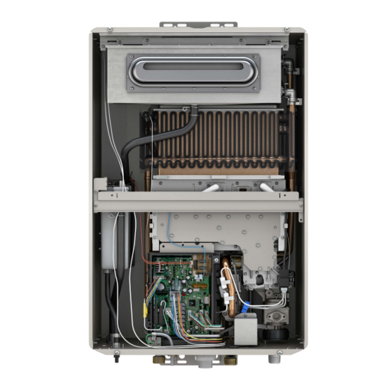
Page 98: How To Remove Components
S V C 8 2 0 ( P ) P o c k e t M a n u a l P a g e HOW TO REMOVE COMPONENTS OUTDOOR UNIT INDOOR UNIT... -
Page 99: Section 1: Control Board Bracket
98 | P a g e S V C 8 2 0 ( P ) P o c k e t M a n u a l Section 1: Control Board Bracket ALWAYS TURN OFF Power, Water & Gas Remove ‘TOP’ center screw from control board mounting bracket. - Page 100 S V C 8 2 0 ( P ) P o c k e t M a n u a l P a g e Remove connectors: ‘M’; ‘T’; & ‘G’. Condensing ONLY: ALSO remove connector ‘P’. *Remove 2 control board bracket screws located on bottom, outer shell of unit.
-
Page 101: Section 2: Blower Motor
100 | P a g e S V C 8 2 0 ( P ) P o c k e t M a n u a l Section 2: Blower Motor ALWAYS TURN OFF Power, Water & Gas Remove control board Bracket to access Blower Motor Section 1... - Page 102 S V C 8 2 0 ( P ) P o c k e t M a n u a l P a g e *Move control board bracket out of way to access blower motor (follow instructions in Section 1). *Remove 3 OUTER screws from blower motor assembly (circled in red).
-
Page 103: Section 3: Flame Rod; Igniter Rod; Igniter Coil
102 | P a g e S V C 8 2 0 ( P ) P o c k e t M a n u a l Section 3: Igniter Rod-Flame Rod-Igniter Coil ALWAYS TURN OFF Power, Water & Gas Flame Rod(s) •... - Page 104 S V C 8 2 0 ( P ) P o c k e t M a n u a l P a g e Igniter Rod Disconnect black igniter cable from igniter rod. Remove igniter rod mounting screws.
-
Page 105: Section 4: Orifice Assembly
104 | P a g e S V C 8 2 0 ( P ) P o c k e t M a n u a l Section 4: Manifold Assembly ALWAYS TURN OFF Power, Water & Gas *Move control board bracket out of way (follow instructions in Section 1). - Page 106 S V C 8 2 0 ( P ) P o c k e t M a n u a l P a g e *Remove 4 screws from lower manifold assembly (circled in green). *Disconnect black igniter coil cable from igniter rod. *Disconnect white Molex from bottom of igniter coil (circled in blue –...
-
Page 107: Section 5: Burner Assembly
106 | P a g e S V C 8 2 0 ( P ) P o c k e t M a n u a l Section 5: Burner Assembly ALWAYS TURN OFF Power, Water & Gas *Move control board bracket out of way (follow instructions in Section 1). *Remove manifold assembly (follow instructions in Section 4). -
Page 108: Section 6: Gas Control Valve
S V C 8 2 0 ( P ) P o c k e t M a n u a l P a g e Section 6: Gas Control Valve ALWAYS TURN OFF Power, Water & Gas Bottom of Unit *Move control board bracket out of way (follow instructions in Section 1). - Page 109 108 | P a g e S V C 8 2 0 ( P ) P o c k e t M a n u a l Section 6: Gas Control Valve ALWAYS TURN OFF Power, Water & Gas Front of gas control valve Gaskets *Remove 2 Molex connectors and clear tube on left side of gas control valve (circled in green).
- Page 110 S V C 8 2 0 ( P ) P o c k e t M a n u a l P a g e Back view of gas control valve *Remove 4 Molex connectors on back of gas control valve (highlighted in corresponding wire color).
- Page 111 110 | P a g e S V C 8 2 0 ( P ) P o c k e t M a n u a l NOTES: _________________________ _________________________ _________________________ _________________________ _________________________ _________________________ _________________________ _________________________ _________________________ _________________________ _________________________ _________________________ _________________________ _________________________...
-
Page 112: Section 7: Water Control Valves
S V C 8 2 0 ( P ) P o c k e t M a n u a l P a g e Section 7: Water Volume Control & Water Bypass Valves ALWAYS TURN OFF Power, Water & Gas Use Service Valves to DRAIN UNIT Remove control board Bracket to access water control valves. - Page 113 112 | P a g e S V C 8 2 0 ( P ) P o c k e t M a n u a l Section 7: Water Volume Control & Water Bypass Valves ALWAYS TURN OFF Power, Water & Gas Use Service Valves to DRAIN UNIT Blower Motor *Remove 4 screws holding compression fittings in place &...
- Page 114 S V C 8 2 0 ( P ) P o c k e t M a n u a l P a g e Side View of water control valve Water bypass valve Water volume control valve *Remove snap ring holding water bypass and water volume control valves together (circled in blue).
-
Page 115: Section 8: Heat Exchanger Thermistor
114 | P a g e S V C 8 2 0 ( P ) P o c k e t M a n u a l Section 8: Heat Exchanger thermistors ALWAYS TURN OFF Power, Water & Gas Use Service Valves to DRAIN UNIT *Remove 2 screws Remove snap ring *Pull Heat Exchanger thermistor out... - Page 116 S V C 8 2 0 ( P ) P o c k e t M a n u a l P a g e Blower Motor *Move control board bracket out of way to access Molex for Heat Exchanger thermistor (follow instructions in Section 1). Mid-Efficiency –...
-
Page 117: Section 9: Outlet Thermistor
116 | P a g e S V C 8 2 0 ( P ) P o c k e t M a n u a l Section 9: Outlet thermistor ALWAYS TURN OFF Power, Water & Gas Use Service Valves to DRAIN UNIT Remove control board Bracket to access outlet thermistor. - Page 118 S V C 8 2 0 ( P ) P o c k e t M a n u a l P a g e Blower Motor *Move control board bracket out of way to access outlet thermistor (follow instructions in Section 1). *Locate Outlet thermistor on lower left side of unit (circled in blue).
-
Page 119: Section 10: Inlet Thermistor
118 | P a g e S V C 8 2 0 ( P ) P o c k e t M a n u a l Section 10: Inlet thermistor ALWAYS TURN OFF Power, Water & Gas Use Service Valves to DRAIN UNIT Remove control board Bracket to access inlet thermistor. - Page 120 S V C 8 2 0 ( P ) P o c k e t M a n u a l P a g e Blower Motor *Move control board bracket out of way to access WHITE Molex for inlet thermistor (follow instructions in Section 1). * To REPLACE thermistor ONLY: Separate WHITE Molex (circled in green).
-
Page 121: Section 11: Ambient Thermistor
120 | P a g e S V C 8 2 0 ( P ) P o c k e t M a n u a l Section 11: Ambient thermistor ALWAYS TURN OFF Power, Water & Gas Remove control board Bracket to diagnose and/or replace ambient thermistor. - Page 122 S V C 8 2 0 ( P ) P o c k e t M a n u a l P a g e Blower Motor To REPLACE thermistor ONLY: *Move control board bracket out of way to access BLUE Molex for ambient thermistor (follow instructions in Section 1).
-
Page 123: Section 12: Control Board
122 | P a g e S V C 8 2 0 ( P ) P o c k e t M a n u a l Section 12: Control Board ALWAYS TURN OFF Power, Water & Gas *Remove ALL Molex connections on control board. *Remove line voltage screws (black &... -
Page 124: How To Program Control Board
S V C 8 2 0 ( P ) P o c k e t M a n u a l P a g e Section 12: Control Board Replacement Procedure Recording Manifold Pressure on ORIGINAL Control Board NOTE: Without this adjustment the water heater may not function properly. - Page 125 124 | P a g e S V C 8 2 0 ( P ) P o c k e t M a n u a l Section 12: Control Board Replacement Procedure Adjusting Manifold Pressure on NEW Control Board NOTE: This adjustment to be performed on NEW control board.
- Page 126 S V C 8 2 0 ( P ) P o c k e t M a n u a l P a g e Section 12: Control Board Replacement Procedure Adjusting Manifold Pressure on NEW Control Board NOTE: This adjustment to be performed on NEW control board. Adjustment of “MAXIMUM”...
- Page 127 126 | P a g e S V C 8 2 0 ( P ) P o c k e t M a n u a l Section 12: Control Board Replacement Procedure Adjusting Manifold Pressure on NEW Control Board NOTE: This adjustment to be performed on NEW control board.
- Page 128 S V C 8 2 0 ( P ) P o c k e t M a n u a l P a g e NOTES: _________________________ _________________________ _________________________ _________________________ _________________________ _________________________ _________________________ _________________________ _________________________ _________________________ _________________________ _________________________ _________________________ _________________________...
- Page 129 128 | P a g e S V C 8 2 0 ( P ) P o c k e t M a n u a l NOTES: _________________________ _________________________ _________________________ _________________________ _________________________ _________________________ _________________________ _________________________ _________________________ _________________________ _________________________ _________________________ _________________________ _________________________...
- Page 130 CUSTOMER SERVICE Parts and Warranty Phone : 1-800-621-5622 Email: parts@rheem.com In keeping with its policy of continuous progress and improvement, Rheem reserves the right to make changes without notice. Rheem Water Heating 1115 Northmeadow Pky ○ Roswell, GA 30076 1.800.621.5622 ○...