Table of Contents
Advertisement
Quick Links
Advertisement
Table of Contents

Related Manuals for Omron Cobra 350 CR/ESD


Summary of Contents for Omron Cobra 350 CR/ESD
- Page 1 Cobra 350 Robot User’s Guide I591-E-05...
- Page 2 Copyright Notice The information contained herein is the property of Omron Adept Technologies, Inc., and shall not be reproduced in whole or in part without prior written approval of Omron Adept Technologies, Inc. The information herein is subject to change without notice and should not be construed as a commitment by Omron Adept Technologies, Inc.
-
Page 3: Table Of Contents
Table of Contents Chapter 1: Introduction 1.1 Product Description Cobra 350 Robots SmartController EX (Option) MotionBlox-40R 1.2 How Can I Get Help? Related Manuals Chapter 2: Safety 2.1 Dangers, Warnings, and Cautions Alert Levels Alert Icons Falling Hazards Special Information 2.2 Safety Precautions User's Responsibilities General Hazards... - Page 4 Table of Contents Upon Unpacking 3.3 Repacking for Relocation 3.4 Environmental and Facility Requirements 3.5 Mounting the Robot Mounting Surface Robot Mounting Procedure Chapter 4: MotionBlox-40R 4.1 Introduction 4.2 Connectors on eMB-40R Interface Panel 4.3 eMB-40R Operation Status LED Status Panel Brake Release Button Brake Release Connector 4.4 Connecting Digital I/O to the System...
- Page 5 Table of Contents 5.7 Cable Connections from eMB-40R to SmartController EX 5.8 Cable Connection from eMB-40R to Robot 5.9 Connecting 24 VDC Power to eMB-40R Specifications for 24 VDC Power Details for 24 VDC Mating Connector Procedure for Creating 24 VDC Cable Installing the 24 VDC Cable 5.10 Connecting 200-240 VAC Power Specifications for AC Power...
- Page 6 Table of Contents Reinstalling the Flange 7.3 User Connections on Robot User Air Lines User Electrical Lines Optional Solenoid Cable Mounting Options for User Connections 7.4 Camera Mounting Camera Channel Camera Bracket Chapter 8: Maintenance 8.1 Periodic Maintenance Schedule 8.2 Warning Labels 8.3 Checking Safety Systems 8.4 Checking Robot Mounting Bolts 8.5 Lubricate Joint 3 Ball Screw...
- Page 7 Table of Contents Chapter 10: Cleanroom Robots 10.1 Cobra 350 CR/ESD Cleanroom Option Introduction Specifications 10.2 Connections 10.3 Requirements 10.4 ESD Control Features 10.5 Maintenance Bellows Replacement Lubrication 10.6 Dimension Drawings 05624-000 Rev. K Cobra 350 User's Guide...
- Page 8 Updated graphics to OAT. Added notes to stopping distance graph section. July, Removed ‘s’ from all “s350” instances. Replaced two Adept logos photos with Omron | adept logos. 2017 Added photos clarifying insertion of Arm Power/Signal cable between robot and eMB-40/60R.
-
Page 9: Chapter 1: Introduction
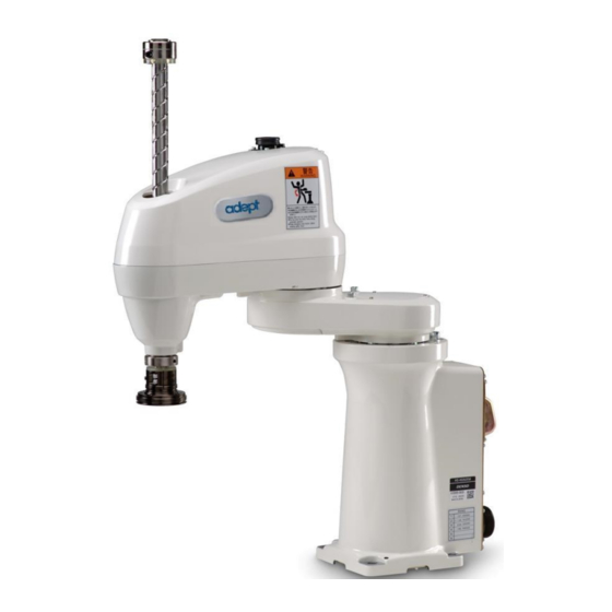
SmartController EX motion controller, which also runs eV+. Mechanical specifications for the Cobra 350 robots are provided in Technical Specifications on page 119. A cleanroom model is also available, the Cobra 350 CR/ESD. See Cleanroom Robots on page 129 for information. Figure 1-1. Cobra 350 Robot 05624-000 Rev. -
Page 10: Smartcontroller Ex (Option)
1.1 Product Description Figure 1-2. Robot Joint Motions Table 1-1. Robot Joint Motion Description Item Description Item Description 1st Joint (J1) 2nd Joint (J2) 3rd Joint (J3) 4th Joint (J4) SmartController EX (Option) The SmartController EX motion controller is the foundation of our family of high-performance distributed motion and vision controllers. -
Page 11: Motionblox-40R
Chapter 1: Introduction 1394 interface is the backbone of SmartServo, the distributed controls architecture supporting our products. The SmartController EX also includes Fast Ethernet and DeviceNet. Figure 1-3. SmartController EX Motion Controller MotionBlox-40R The MotionBlox-40R (eMB-40R) Distributed Servo Controller controls the amplifiers to power the high-power motors of the Cobra 350 robot, and runs the eV+ operating system for motion control of the robot. -
Page 12: How Can I Get Help
Figure 1-4. MotionBlox-40R 1.2 How Can I Get Help? You can access information sources on our corporate web site: http://www.ia.omron.com Related Manuals This manual covers the installation, operation, and maintenance of an Cobra 350 robot system. There are additional manuals that cover programming the system, reconfiguring installed com- ponents, and adding other optional components. -
Page 13: Chapter 2: Safety
Chapter 2: Safety 2.1 Dangers, Warnings, and Cautions Alert Levels There are three levels of alert notation used in our manuals. In descending order of import- ance, they are: DANGER: Identifies an imminently hazardous situation which, if not avoided, is likely to result in serious injury, and might result in fatality or severe property damage. -
Page 14: Special Information
2.2 Safety Precautions Safety Barriers To protect personnel from coming in contact with robot unintentionally or objects entering robot’s operation zone, install user-supplied safety barriers in the workcell. Special Information There are several types of notation used to call out special information. IMPORTANT: Information to ensure safe use of the product. -
Page 15: General Hazards
Figure 2-1. Read Manual and Impact Warning Labels The robot system must not be used for purposes other than described in Intended Use of the Robot on page 17. Contact your local Omron support if you are not sure of the suit- ability for your application. -
Page 16: What To Do In An Emergency Or Abnormal Situation
2.3 What to Do in an Emergency or Abnormal Situation Skilled persons have technical knowledge or sufficient experience to enable them to avoid the dangers, electrical and/or mechanical Instructed persons are adequately advised or supervised by skilled persons to enable them to avoid the dangers, electrical and/or mechanical All personnel must observe industry-prescribed safety practices during the installation, oper- ation, and testing of all electrically-powered equipment. -
Page 17: Robot Behavior
Limiting Devices There are no dynamic or electro-mechanical limiting devices provided by Omron Adept Tech- nologies, Inc. The robot does not have safety-rated soft axis or space limiting. However, the user can install their own safety rated (category 0 or 1) dynamic limiting devices if needed, that comply with ISO 10218-1, Clause 5.12.2. -
Page 18: Non-Intended Use
Cause injury to personnel Damage itself or other equipment Reduce system reliability and performance If there is any doubt concerning the application, ask your your local Omron support to determ- ine if it is an intended use or not. 2.6 Additional Safety Information We provide other sources for more safety information: Manufacturer’s Declaration of Incorporation... -
Page 19: Disposal
WEEE (Waste Electronics and Electrical Equipment). All electrical and elec- tronic products should be disposed of separately from the municipal waste system via des- ignation collection facilities. For information about disposal of your old equipment, contact your local Omron support. 05624-000 Rev. K Cobra 350 User's Guide... -
Page 21: Chapter 3: Robot Installation
If the items received do not match the packing slip, or are damaged, do not sign the receipt. Contact your local Omron support as soon as possible. If the items received do not match your order, please contact your local Omron support imme- diately. -
Page 22: Environmental And Facility Requirements
3.4 Environmental and Facility Requirements 3.4 Environmental and Facility Requirements The robot system installation must meet the operating environment requirements shown in the following table. Table 3-1. Robot System Operating Environment Requirements Ambient temperature 5 to 40°C (41 to 104°F) Humidity 5% to 90%, noncondensing Altitude... -
Page 23: Mounting Surface
Chapter 3: Robot Installation Table 3-2. Transporting Robot Description Item Description Person 1 Person 2 CAUTION: PERSONAL INJURY OR PROPERTY DAMAGE RISK Do not hold the robot by parts other than those shown above. Mounting Surface The Cobra 350 robot is designed to be mounted on a smooth, flat, level surface. The mounting surface must be rigid enough to prevent vibration and flexing during robot operation. -
Page 24: Robot Mounting Procedure
3.5 Mounting the Robot 4x Ø 12 R 1500 134 ± 0.005 R 1500 +0.012 2x Ø 6 H7 Figure 3-2. Robot Base Mounting Hole Pattern (Units in mm) Table 3-3. Robot Base Mounting Hold Pattern Description Item Description Through Holes Allow 291 mm for cabling Robot Mounting Procedure 1. - Page 25 Chapter 3: Robot Installation Drill a dowel pin hole Ø6 mm, H7 for the internally threaded positioning pin, 10 to 15 mm deep. WARNING: PERSONAL INJURY OR PROPERTY DAMAGE RISK Do not attempt to extend the inner or outer links of the robot until the robot has been secured in position. Failure to comply could result in the robot falling and causing either personnel injury or equipment damage.
- Page 26 3.5 Mounting the Robot 7. Slowly lower the robot while aligning the base and the tapped mounting holes in the mounting surface. NOTE: The base casting of the robot is aluminum and can easily be dented if bumped against a harder surface. 8.
-
Page 27: Chapter 4: Motionblox-40R
Chapter 4: MotionBlox-40R 4.1 Introduction The MotionBlox-40R (eMB-40R) is a distributed servo controller and amplifier. It has a ded- icated digital signal processor to communicate, coordinate, and execute servo commands. The eMB-40R consists of: a distributed servo amplifier a RISC processor for servo loop control a node on the IEEE 1394 network a power controller that uses single-phase AC power, 200-240 Volts a status panel with a 2-digit alpha-numeric display to indicate operating status and... -
Page 28: Connectors On Emb-40R Interface Panel
4.2 Connectors on eMB-40R Interface Panel 4.2 Connectors on eMB-40R Interface Panel Figure 4-2. eMB-40R Interface Panel Table 4-2. Connectors on the eMB-40R Interface Panel Item Name Description XSYSTEM Connects to the controller XSYS connector. Requires an eAIB XSLV Adapter cable to connect to the XSYS cable, or an eAIB XSYS cable (HDB44-to-DB9, male). -
Page 29: Emb-40R Operation
Chapter 4: MotionBlox-40R 4.3 eMB-40R Operation Status LED The Status LED indicator is located near the top of the eMB-40R. See the following figure. This is a bi-color, red and green LED. The color and blinking pattern indicates the status of the robot. -
Page 30: Status Panel
4.3 eMB-40R Operation Table 4-4. Status LED Definition LED Status Description 24 VDC not present Green, Slow Blink High Power Disabled Green, Fast Blink High Power Enabled Green/Red Blink Selected Configuration Node Red, Fast Blink Fault, see Status Panel Display Solid Green or Red Initialization or Robot Fault Status Panel... - Page 31 Turn high power back on and restart the program. If the error persists, con- tact your local Omron support. *RSC Power Fail- -670 A loss of AC power was Check user AC power ure* detected connections for shorts or opens.
- Page 32 / disabled via ACE. None Firmware version mis- Contact your local match. Omron support. *1394 com- -927 The IEEE 1394 com- This will occur nor- munications munications system has mally if the...
- Page 33 Check AC connections and re- enable high power. If the error persists, contact your local Omron support. None Servo initialization None, unless an ini- stages. These steps nor- tialization code per- mally sequence (I0, I1, sists longer than 30 …) on the display during...
- Page 34 Explanation User Action Code Message Code PA-4 Power Chassis User's Guide for details. Contact your local Omron support if the error persists. *Power system -1115 The high-voltage DC bus Contact your local failure* Code 2 to the regenerative Omron support.
- Page 35 If the problem per- Fault* Code 2 ienced a failure on chan- sists, contact your nel 1 during the cyclic local Omron support. check of dual-channel power system. This may indicate a welded relay contact or other hard- ware failure.
- Page 36 Code Message Code only, on select robots ing normal oper- which have the CAT-3 ation, contact your teach mode option local Omron support. installed. *Safety System -1109* A watchdog circuit that Contact your local Fault* Code 9 cross-checks the clocks Omron support.
-
Page 37: Brake Release Button
Chapter 4: MotionBlox-40R Brake Release Button The Brake Release button is located at the top right of the eMB-40R, as shown in Controls and Indicators on eMB-40R on page 29. Under some circumstances you may want to manually pos- ition Joints 3 and 4 without turning on high power. You can use the Brake Release button for this purpose. -
Page 38: Connecting Digital I/O To The System
You can connect digital I/O to the system in several different ways. See the following table and figure. NOTE: A typical IO Blox configuration is shown in Figure 4-4. Other con- figurations may be possible. Contact your local Omron support for more inform- ation. Table 4-7. Digital I/O Connection Options... -
Page 39: Using Digital I/O On Emb-40R Xio Connector
Chapter 4: MotionBlox-40R Table 4-8. Default Digital I/O Signal Configuration, Single Robot System Item Location Type Signal Range Optional SmartController EX, XDIO 12 Inputs 1001 - 1012 connector 8 Outputs 0001 - 0008 eMB-40R 1 XIO connector 12 Inputs 1097 - 1108 8 Outputs 0097 - 0104 Optional IO Blox 1... - Page 40 4.5 Using Digital I/O on eMB-40R XIO Connector Table 4-9. XIO Signal Designations Signal Signal Designation Bank Pin Locations Number 24 VDC Common 1 Input 1.1 1097 Pin 1 Input 2.1 1098 Pin 10 Pin 19 Input 3.1 1099 Input 4.1 1100 Input 5.1 1101...
-
Page 41: Optional I/O Products
Chapter 4: MotionBlox-40R Optional I/O Products These optional products are also available for use with digital I/O: XIO Breakout Cable, 5 m, with flying leads on user’s end (see XIO Breakout Cable on page 46). It is not compatible with the XIO Termination Block mentioned below. XIO Termination Block, with terminals for user wiring, plus input and output status LEDs. - Page 42 4.5 Using Digital I/O on eMB-40R XIO Connector NOTE: The input current specifications are provided for reference. Voltage sources are typically used to drive the inputs. Typical Input Wiring Example 1097 1098 1099 1100 1101 1102 +24V 1103 1104 1105 1106 1107 1108...
- Page 43 Chapter 4: MotionBlox-40R Table 4-11. Typical User Wiring for XIO Input Signal Description Item Description Supplied Equipment User-supplied Equipment Equivalent Circuit Wiring Terminal Block Typical User Input Signals (part present sensor, feeder empty sensor, part jammed sensor, sealant ready sensor, etc.) Bank 1 configured for Sinking (NPN) inputs Bank 2 configured for Sourcing (PNP) inputs Input Bank 1 Input Bank 2...
-
Page 44: Xio Output Signals
4.5 Using Digital I/O on eMB-40R XIO Connector XIO Output Signals The eight digital outputs share a common, high-side (sourcing) driver IC. The driver is designed to supply any kind of load with one side connected to ground. It is designed for a range of user-provided voltages from 10 to 24 VDC, and each channel is capable of up to 0.7 A of current. - Page 45 Chapter 4: MotionBlox-40R Typical Output Wiring Example +24 VDC 0097 0098 0099 0100 0101 0102 0103 0104 Figure 4-6. Typical User Wiring for XIO Output Signals Table 4-13. Typical User Wiring for XIO Output Signal Description Item Description Supplied Equipment User-supplied Equipment Wiring Terminal Block Typical User Loads Equivalent Circuit...
-
Page 46: Xio Breakout Cable
4.5 Using Digital I/O on eMB-40R XIO Connector XIO Breakout Cable The XIO Breakout cable is available as an option—see the following figure. This cable connects to the XIO connector on the eMB-40R, and provides flying leads on the user’s end, for con- necting input and output signals in the workcell. - Page 47 Chapter 4: MotionBlox-40R Table 4-14. XIO Breakout Cable Wire Chart Signal Pin No. Designation Wire Color Pin Locations White 24 VDC White/Black Common 1 Input 1.1 Red/Black Pin 1 Input 2.1 Yellow Pin 10 Pin 19 Input 3.1 Yellow/Black Input 4.1 Green Input 5.1 Green/Black...
-
Page 48: Mounting The Emb-40R
4.6 Mounting the eMB-40R 4.6 Mounting the eMB-40R Dimensions and Mounting Holes See the following figure for dimensions of the eMB-40R chassis and mounting holes. 197.8 32.7 45.7 129.54 32.7 32.7 67.3 106.7 170.2 182.9 197.8 197.8 222.3 228.6 6X, SHCS,M4 X 6 45.7 Figure 4-8. -
Page 49: Mounting Clearances
Chapter 4: MotionBlox-40R NOTE: 112 mm clearance required in front of unit to remove amplifiers from box enclosure. Mounting Clearances NOTE: The mounting of the eMB-40R and all terminations at the eMB-40R must be performed in accordance with all local and national standards. The following space must be left around the eMB-40R for proper cooling: 100 / 200 Figure 4-9. -
Page 51: Chapter 5: System Cable Installation
Chapter 5: System Cable Installation 5.1 System Cables, without SmartController EX The letters in the following figure correspond to the letters in Table 5-1. Cables and Parts Description (without SmartController EX). The numbers in the following figure correspond to the numbers in Table 5-2. Connections Installation Steps The figure includes the optional T20 pendant and optional SmartVision MX industrial PC. -
Page 52: List Of Cables And Parts
5.1 System Cables, without SmartController EX NOTE: See System Cable Installation on page 51 for additional system ground- ing information. List of Cables and Parts Open the Accessory box and locate the eAIB XSYSTEM cable. Cable and peripheral con- nections are shown in the preceding figure. Installation steps are covered in Connection Install- ation Overview on page 54. - Page 53 Chapter 5: System Cable Installation Item Description Part # User- Notes Standard Option supplied The following three items are available, as an option, in the power supply/cable kit 90565-010 VAC Power Cable 04118- 200-240 VAC, single phase 24 VDC Power Cable 04120- 24 VDC, 6 A Power 04536-...
-
Page 54: Connection Installation Overview
5.1 System Cables, without SmartController EX Connection Installation Overview The numbers in Figure 5-1. System Cable Diagram for Cobra 350 Robot with eMB-40R, Pend- ant, and Vision correspond to the steps in the cable installation overview description table. Refer to System Cables, without SmartController EX on page 51 for more information about cables and parts. -
Page 55: Other Cables
Chapter 5: System Cable Installation Step Connection Description Item Connect Ethernet cable from switch to eMB-40R. M, O, R Refer to Connecting the PC to the SmartController EX on page 65 for more information. Connect Ethernet cable from switch to SmartVision MX, if used. N, O Refer to Connecting the PC to the SmartController EX on page 65 for more information. -
Page 56: System Cables, With Optional Smartcontroller Ex, Smartvision Mx
5.2 System Cables, with Optional SmartController EX, SmartVision MX 5.2 System Cables, with Optional SmartController EX, SmartVision MX The letters in the following figure correspond to the letters in Table 5-3. Cables and Parts Description (with SmartController EX) on page 57. When the optional SmartController EX is included in the system, the Pendant, Front Panel, and XUSR connections must connect to the SmartController EX. -
Page 57: Installing A Smartcontroller Ex Motion Controller
Chapter 5: System Cable Installation Installing a SmartController EX Motion Controller Refer to the SmartController EX User’s Guide for complete information on installing the optional SmartController EX. This list summarizes the main steps. 1. Mount the SmartController EX and Front Panel. 2. - Page 58 5.2 System Cables, with Optional SmartController EX, SmartVision MX Part Cable and Parts User- Notes Part # Standard Option List supplied T20 Pendant Bypass 10048- XMCP Jumper Plug Plug (G), T20 Bypass Plug (H), or T20 Pendant must be used. T20 Pendant Adapter 10051- Cable...
-
Page 59: Cable Installation Overview
Chapter 5: System Cable Installation The XUSR, XMCP, and XFP jumpers intentionally bypass safety connections so you can test the system functionality during setup. WARNING: PERSONAL INJURY RISK Under no circumstances should you run a Cobra 350 system, in production mode, with all three jumpers installed. This would leave the system with no E- Stops. -
Page 60: Optional Cables
5.3 Optional Cables Step Connection Part Connect Ethernet cable to SmartController EX, if used. Connect Ethernet cable to SmartVision MX, if used. N, U Connect IEEE 1394 cable between SmartController EX and eMB-40R O, R SmartServo. Refer to Cable Connections from eMB-40R to SmartController EX on page 65 for more information. - Page 61 Chapter 5: System Cable Installation XSYSTEM ENET ENET 24 V 3000 ± 50 Servo 200 - 240 V 600 ± 25 SmartController EX 500 ± 25 Figure 5-3. System Cable Diagram with Belt Encoders (Units in mm) Table 5-5. Conveyor Belt Encoder Cables Description User- Item Description...
- Page 62 5.3 Optional Cables User- Item Description Part # Standard Option Notes supplied Belt Encoder 2 Connector M12 Female, 8-pin SmartController EX 19300- (optional) SmartController EX Belt 09550- HDB26 Encoder Y Adapter Cable Con- Female nector Belt Branch Connector, DB15 Male Encoder 1 and 2 Belt Branch Connector, DB15 Male...
- Page 63 Chapter 5: System Cable Installation NOTE: Cable shields connected to DSUB shell. PIN 25 (TXD) PIN 3 PIN 26 (RXD) PIN 2 PIN 9 PIN 1 PIN 18 (GND) PIN 1 PIN 5 PIN 5 SHIELD SHIELD PIN 10 PIN 18 PIN 6 PIN 26 PIN 19...
-
Page 64: Installing The Smartcontroller Ex
5.4 Installing the SmartController EX PIN 15 PIN 2 (ENC1_A+) PIN 7 PIN 3 (ENC1_A-) PIN 14 PIN 11 (ENC1_B+) PIN 6 PIN 12 (ENC1_B-) PIN 13 PIN 19 (ENC1_Z+) PIN 5 PIN 20 (ENC1_Z-) PIN 8 PIN 1 PIN 11 PIN 4 (ENC2_A+) PIN 3 PIN 5 (ENC2_A-) -
Page 65: Installing The Ace Software
Chapter 5: System Cable Installation 6. Install a user-supplied ground wire between the SmartController EX and ground. 7. Install the ACE software on the user-supplied PC (see the following section). 5.5 Installing the ACE Software The ACE software is installed from the ACE software media. 1. -
Page 66: Cable Connection From Emb-40R To Robot
5.8 Cable Connection from eMB-40R to Robot the eMB-40R XSYSTEM connector, and tighten the latching screws. If you are upgrading from an MB-40R to an eMB-40R, you can use an eAIB XSLV adapter cable between your existing XSYS cable and the XSYSTEM connector on the new eMB-40R. -
Page 67: Connecting 24 Vdc Power To Emb-40R
Using an underrated supply can cause system problems and prevent your equipment from operating correctly. Table 5-8. Recommended 24 VDC Power Supplies Mount Vendor Name Model Ratings OMRON S8FS-G15024C 24 VDC, 6.5 A, 150 W Front Mount OMRON S8FS-G15024CD 24 VDC, 6.5 A, 150 W DIN-Rail Mount 05624-000 Rev. -
Page 68: Details For 24 Vdc Mating Connector
5.9 Connecting 24 VDC Power to eMB-40R Details for 24 VDC Mating Connector The 24 VDC mating connector and two pins are supplied with each system. They are shipped in the cable/accessories box. Table 5-9. 24 VDC Mating Connector Specs Connector Details Connector receptacle, 2-position, type: Molex Saber, 18 A, 2-Pin... -
Page 69: Installing The 24 Vdc Cable
Chapter 5: System Cable Installation 6. Prepare the opposite end of the cable for connection to the user-supplied 24 VDC power supply, including a terminal to attach the cable shield to frame ground. Installing the 24 VDC Cable Do not turn on the 24 VDC power until instructed to do so in the next chapter. 1. -
Page 70: Connecting 200-240 Vac Power
5.10 Connecting 200-240 VAC Power Table 5-10. User-Supplied 24 VDC Cable Description Description Item eMB-40R Servo Controller User-supplied Power Supply, 24 VDC User-supplied shielded power cable Frame Ground Attach shield from user-supplied cable to ground screw on eMB-40R Interface Panel Attach shield from user-supplied cable to side of controller using star washer and M3 x 6 screw. -
Page 71: Specifications For Ac Power
Chapter 5: System Cable Installation Specifications for AC Power Table 5-11. Specifications for 200/240 VAC User-Supplied Power Supply Auto-Ranging Recommended Minimum Maximum Nominal Frequency/ External Circuit Operating Operating Voltage Phasing Breaker, User- Voltage Voltage Ranges Supplied 200 V to 240 V 180 V 264 V 50/60 Hz, 1-phase... - Page 72 5.10 Connecting 200-240 VAC Power AC Power Diagrams F1 10A Figure 5-11. Typical AC Power Installation with Single-Phase Supply Table 5-12. AC Power Installation with Single-Phase Supply Description Item Description Single-phase 200-240 VAC, 20 A L = Line N = Neutral E = Earth Ground User-supplied, must be slow-blow.
-
Page 73: Details For Ac Mating Connector
Chapter 5: System Cable Installation Table 5-13. AC Power Installation with Three-Phase Supply Description Item Description Three-phase 200-240 VAC L = Line N = Neutral E = Earth Ground F4 and F5 are user-supplied, must be slow-blow. User-supplied AC power cable eMB-40R single-phase 200-240 VAC 200-240 VAC Details for AC Mating Connector The AC mating connector is supplied with each system. -
Page 74: Installing Ac Power Cable To Emb-40R
5.10 Connecting 200-240 VAC Power 7. Connect each wire to the correct terminal screw, and tighten the screw firmly. 8. Tighten the screws on the cable clamp. 9. Replace the cover and tighten the screw to seal the connector. 10. Prepare the opposite end of the cable for connection to the facility AC power source. Figure 5-13. -
Page 75: Grounding The Robot System
Chapter 5: System Cable Installation 5.11 Grounding the Robot System Proper grounding is essential for safe and reliable robot operation. Follow these recom- mendations to properly ground your robot system. NOTE: The resistance of the ground conductor must be ≤ 10 Ω. Ground Point on Robot Base The user can install a ground wire at the robot base to ground the robot. -
Page 76: Robot-Mounted Equipment Grounding
5.12 Installing User-Supplied Safety Equipment XSYSTEM ENET ENET Servo 200 - 240V Figure 5-15. Earth Ground Location Table 5-16. Earth Ground Location Description Item Description Robot Interface Panel Ground Label Ground Screw Robot-Mounted Equipment Grounding The Cobra 350 Joint 3 quill and tool flange are not reliably grounded to the robot base. If haz- ardous voltages are present at any user-supplied robot-mounted tooling, you must install a ground connection from that tooling to the ground point on the robot base. - Page 77 Chapter 5: System Cable Installation The user-supplied safety and power-control equipment connects to the system through the XUSR and XFP connectors on the eMB-40R XSYSTEM cable. The XUSR connector (25-pin) and XFP (15-pin) connector are both female D-sub connectors. Refer to the following table for the XUSR pin-out descriptions.
- Page 78 5.12 Installing User-Supplied Safety Equipment Table 5-18. Contacts Provided by the XFP Connector Description Requirements for User- Pairs Supplied Front Panel Voltage-Free Contacts Provided by Customer 1, 9 Front Panel E-Stop CH 1 User must supply N/C con- tacts 2, 10 Front Panel E-Stop CH 2 User must supply N/C con- tacts...
- Page 79 Chapter 5: System Cable Installation Table 5-19. Remote Pendant Connections on the XMCP Connector Pin XMCP Description (15-Pin D-Sub) 1, 9 Pendant E-Stop Push-button CH 1 2, 10 Pendant E-Stop Push-button CH 2 3, 11 Pendant Enable CH 1 (Hold-to-run) 4, 12 Pendant Enable CH 2 (Hold-to-run) Serial GND/Logic GND...
- Page 80 5.12 Installing User-Supplied Safety Equipment The following figure shows an E-Stop diagram for the system. See System Cable Installation on page 51 for a description of the functionality of this circuit. XSYSTEM-31 XSYSTEM-32 XSYSTEM-31 (XFP-6) (XFP-1) (XFP-2) XSYSTEM-3 (XFP-5) XSYSTEM-33 (XFP-13) XSYSTEM-34 (XFP-14) XSYSTEM-20 (XFP-10)
- Page 81 Chapter 5: System Cable Installation Table 5-20. E-Stop Circuit on XUSR and XFP Connectors Description Item Description ESTOP 24 V Source ESTOP Ground Front Panel ESTOP Pushbutton T20 ESTOP Pushbutton User E-Stop and Gate Interlock (jumper closed when not used, must open both chan- nels independently if used) LINE E-Stop (external user E-Stop system) T20 Pendant Enable Muted Safety Gate - Active in auto mode only (jumper closed when not used)
-
Page 82: Emergency Stop Circuits
5.12 Installing User-Supplied Safety Equipment ESTOPSRC 15PDSUBM ESTOPFP1 24 VS ESTOPFP2 MANUALSRC1 5 VD MANUALRLY1 MANUALSRC2 MANUALRLY2 HPLT5V HIPWRLT HIPWRREQ SYSPWRLT HPLT5 V MANUALSRC2 5 VD 24 VS ESTOPSRC MANUALSRC1 SYSPWRLT SWL1 2-PIN_MINI HIPWRLT MANUALRLY2 ESTOPFP2 MANUALRLY1 HIPWRREQ ESTOPFP1 Figure 5-17. Front Panel Schematic Table 5-21. - Page 83 MCP ENABLE, or the Muted Safety gate. If you have a specific need in this area, contact your local Omron support for information on alternate indicating modes. Two pairs of pins on the XUSR connector (pins 7, 20 and 8, 21) provide voltage-free contacts, one for each channel, to indicate whether the E-Stop chain, as described above, on that channel is closed.
-
Page 84: Remote Manual Mode
5.12 Installing User-Supplied Safety Equipment WARNING: PERSONAL INJURY RISK Whenever possible, manual mode operations should be performed with all per- sonnel outside the workspace. WARNING: PERSONAL INJURY RISK If you want the cell gate to always cause a robot shutdown, wire the gate switch contacts in series with the user E-Stop inputs. Do not wire the gate switch into the Muted Safety Gate inputs. -
Page 85: User High Power On Indication
Chapter 5: System Cable Installation User High Power On Indication In the optional SmartController EX, eV+ controls a normally-open relay contact on the XDIO connector (pins 45, 46, see the table System Cable Installation on page 51), that will close when high power has been enabled. -
Page 86: Remote Pendant Usage
5.12 Installing User-Supplied Safety Equipment Schematic on page 82 for a schematic drawing of the Front Panel, and see the table Contacts Provided by the XFP Connector on page 78 for a summary of connections and pin numbers. NOTE: The system was evaluated by Underwriters Laboratory with our Front Panel. -
Page 87: Chapter 6: System Operation
Chapter 6: System Operation 6.1 Status Panel Codes The status panel display on the eMB-40R displays alpha-numeric codes that indicate the oper- ating status of the robot, including detailed fault codes. The chapter on MotionBlox-40R gives definitions of the fault codes. These codes provide details for quickly isolating problems during troubleshooting. -
Page 88: Front Panel
6.3 Front Panel CAUTION: PROPERTY DAMAGE RISK When the Brake Release button is pressed, Joint 3 may drop to the bottom of its travel. To prevent possible damage to the equipment, make sure that Joint 3 is supported while releasing the brake and verify that the end-effector or other installed tooling is clear of all obstructions. -
Page 89: Initial Power-Up Of The System
Chapter 6: System Operation WARNING: PERSONAL INJURY RISK If an operator is going to be in the work cell in manual mode, it is strongly recommended that the operator carry an enabling device. The Enable button on the manual control pendant is such a device. 4. - Page 90 6.4 Initial Power-up of the System WARNING: PERSONAL INJURY OR PROPERTY DAMAGE RISK After installing the robot, you must test it before you use it for the first time. Failure to do this could cause death, or serious injury or equipment damage. Mechanical Checks Verify that the robot is mounted level and that all fasteners are properly tightened Verify that any end-of-arm tooling is properly installed Verify that all other peripheral equipment is properly installed, such that it is safe to turn on power to the robot system...
-
Page 91: System Start-Up Procedure
Double-click the ACE icon on your Windows desktop, From the Windows Start menu bar, select: Start > Programs > Omron > ACE x.y. where x is the ACE major version, and y is the ACE minor version. For example, for ACE 3.6, it would be: Start >... -
Page 92: Verifying E-Stop Functions
6.5 Learning to Program the Cobra 350 Robot Using ACE to Enable High Power 1. From the ACE main menu, click the Enable High Power icon 2. Press and release the blinking High Power button on the Front Panel within 10 seconds. The Front Panel is shown in Chapter 6: (If the button stops blinking, you must Enable Power again.) NOTE: The use of the blinking High Power button can be configured (or... -
Page 93: Chapter 7: Optional Equipment Installation
Chapter 7: Optional Equipment Installation 7.1 Installing End-Effectors The user is responsible for providing and installing any end-effector or other end-of-arm tool- ing. End-effectors can be attached to the tool flange using four M6 screws. See Tool Flange Dimensions for Cobra 350 Robots (Units in mm) on page 122 for a detailed dimension draw- ing of the tool flange. -
Page 94: Reinstalling The Flange
7.3 User Connections on Robot Figure 7-1. Tool Flange Removal Table 7-1. Tool Flange Removal Description Item Description Tool Flange Assembly Quill Shaft Setscrew M4 Socket-head Cap Screws Reinstalling the Flange 1. Slide the flange up on the quill shaft as far as it will go, and rotate it until the setscrew is lined up with the flat section on the quill shaft. - Page 95 Chapter 7: Optional Equipment Installation 1 2 3 4 5 6 7 8 10 11 12 13 14 15 16 17 18 19 Figure 7-2. User Air and Electrical Connectors on Robot Table 7-2. User Air and Electrical Connectors on Robot Description Item Description Brake release switch...
-
Page 96: User Electrical Lines
7.3 User Connections on Robot User Electrical Lines There are 19 user electrical lines that run from CN20 at the back of the robot, up to CN21 on the top of Joint 2, as shown in the previous figure. Maximum current per line is 1 Amp. Use the supplied mating connector sets, shown in the following table, for CN20 and CN21. -
Page 97: Mounting Options For User Connections
Chapter 7: Optional Equipment Installation Signal from XDIO on Signal from XDIO on CN21 Pin # SmartController EX CN21 Pin # SmartController EX Ground Inputs 1001 to 1005 are preconfigured as low-active (sinking) inputs. Outputs 0007 and 0008 are preconfigured as high-side (sourcing) outputs. Limited to a combined total of 1 A of current. - Page 98 7.3 User Connections on Robot Routing User Connections Through the Quill (J3) You can route air and electrical lines from the CN21 connector or the air line ports on the top of the outer arm (Joint 2) through the hollow center (Ø14 mm) of the quill. CAUTION: PROPERTY DAMAGE RISK If routing lines in this manner, make sure that, when the robot is in motion, including when the quill is moving, the air and electrical lines do not become...
-
Page 99: Camera Mounting
Chapter 7: Optional Equipment Installation Item Description User Air and Electrical Lines Stay Attached to Underside of Outer Arm Using M3 Bolts 30.00 2x dia. 5.6 24.9 50.0 dia. 5.1 101.6 76.2 R 2.0 30.0 Figure 7-5. Dimensions for Fabricating User-Supplied Stay (Units in mm) 7.4 Camera Mounting Camera Channel An optional camera channel (40861-00830) and camera mounting block (40861-00660) are... -
Page 100: Camera Bracket
7.4 Camera Mounting 4x M3 x 12.7 Figure 7-6. Camera Mounting Details (Units in mm) Table 7-7. Camera Mounting Description Item Description Camera Bracket Camera Channel Camera Mounting Block Camera Bracket A camera can be mounted on the Cobra 350 by installing a user-supplied camera bracket. The bracket is installed on the underside of the robot—see the following figure for the location and dimensions of the mounting holes. - Page 101 Chapter 7: Optional Equipment Installation 0.25 A 127.3 177.0 22.3 0.25 B 101.8 14.2 16.00 0.25 B Figure 7-7. Camera Bracket Drawing, 1 of 2 (Units in mm) Unless otherwise specified: Dimensions apply after process. Interpret drawing per ANSI Y14.5 Tolerances: 2 place decimals: +/- 0.8 mm 2 place decimals: +/- 0.38...
- Page 102 7.4 Camera Mounting (10°) 92.5 31.0 22.6 57.2 82.0 25.4 R 50.8 46.2 32.3 30.00 dia. 4.1 dia. 26.9 111.1 R 12.7 15º 15º R 6.4 167.4 14.2 23.1 R 50.8 44.45 78.2 22.86 13.7 10.9 R Full 87.6 59.99 50.8 25.4 20.6...
-
Page 103: Chapter 8: Maintenance
Chapter 8: Maintenance 8.1 Periodic Maintenance Schedule The following table gives a summary of the preventive maintenance procedures and guidelines on frequency. Table 8-1. Inspection and Maintenance Item Period Reference Safety Labels 1 week Check E-Stop, enable and key 3 months Checking Safety Systems switches, and barrier interlocks on page 105... - Page 104 8.2 Warning Labels All warning labels on the Cobra 350 should be checked on a weekly basis for being present and legible. If any of the labels are missing or illegible, they should be replaced. The labels, with part numbers, are: Read User’s Guide, Impact Warning Label, 18241-000 These labels instruct the user to read the user’s guide before using the robot, and to be aware of the potential of impact by the robot.
-
Page 105: Checking Safety Systems
Chapter 8: Maintenance 8.3 Checking Safety Systems These tests should be done every six months. 1. Test operation of: E-Stop button on Front Panel E-Stop button on pendant Enabling switch on pendant Auto/Manual switch on Front Panel NOTE: Operating any of the above switches should disable High Power. 2. -
Page 106: Replacing Encoder Battery
8.6 Replacing Encoder Battery Figure 8-3. (1) Lubrication of Joint 3 Quill Shaft 2. Raise the Joint 3 quill shaft to the upper position. 3. Apply grease to the entire shaft. See the preceding table for details. 4. Move the Joint 3 shaft up and down to distribute the grease. Wipe off any excess grease. 8.6 Replacing Encoder Battery The data stored by the encoders is protected by 3.6 V lithium backup batteries located in the base of the robot. -
Page 107: Replacement Procedure
Chapter 8: Maintenance Replacement Procedure NOTE: In the following steps, the top and bottom batteries are referred to assum- ing a table-mount for the robot, and the orientation is as shown in the figures. NOTE: Always leave at least two batteries connected at all times. Failure to do so may lose the encoder positional data, requiring factory recalibration. - Page 108 8.6 Replacing Encoder Battery Figure 8-5. Removing (1) Battery Cover 8. Attach the first new backup battery to the unused connector on the battery board. See the following figures for details. NOTE: Always leave at least two batteries connected at all times. Failure to do so may lose the encoder positional data, requiring factory recal- ibration.
- Page 109 Chapter 8: Maintenance Figure 8-7. Attaching New Backup Battery, (1) Unused Connector (2) New Battery 9. Disconnect the top old battery from the battery board, and then remove it from the holder. Figure 8-8. Top Old Backup Battery Removed from (1) Holder 10.
-
Page 110: Inspecting Timing Belts
1. Turn off power to the eMB-40R and SmartController EX, if present. 2. Visually inspect the timing belts for Joint 3 and Joint 4 for excessive wear or missing teeth. 3. If you discover any problems, contact your local Omron support. 8.8 Replacing the eMB-40R Amplifier Remove the eMB-40R Amplifier 1. -
Page 111: Installing A New Emb-40R
Chapter 8: Maintenance See MotionBlox-40R on page 27 for locations of connectors. 5. Disconnect the 200/240 VAC supply cable from the eMB-40R AC Input connector. 6. Disconnect the eAIB XSYS cable from the eMB-40R XSYSTEM connector. If the system was upgraded from an MB-40R to an eMB-40R, you may need to dis- connect the XSYS cable and eAIB XSLV Adapter from the XSYSTEM connector. -
Page 112: Safety Commissioning Utilities
8.9 Commissioning a System with an eMB-40R If the system will not power up, and the robot status display shows SE, you need to commission the system. If the system will not power up in Manual mode, and the robot status display shows TR, you need to commission the system. - Page 113 Chapter 8: Maintenance Figure 8-10. (1) Front Panel Key Switch in Auto Mode No E-Stops can be activated. For Configuration (E-Stop and Teach Restrict), the eAIB Commissioning Jumper must be plugged into the XBELTIO jack on the eMB-40R. NOTE: This is the only time that this jumper will be used. It is part num- ber 11901-000, and must be removed for Verification and normal oper- ation.
-
Page 114: E-Stop Configuration Utility
8.9 Commissioning a System with an eMB-40R E-Stop Configuration Utility This utility sets the E-Stop hardware delay to factory specifications. NOTE: Ensure that the commissioning jumper is plugged into the XBELTIO jack on the eMB-40R before you start this procedure. Procedure NOTE: In this procedure, the word “controller”... -
Page 115: Teach Restrict Configuration Utility
Chapter 8: Maintenance Teach Restrict Configuration Utility This utility sets the hardware Teach Restrict maximum speed parameter to factory spe- cifications. NOTE: Ensure that the commissioning jumper is plugged into the XBELTIO jack on the eMB-40R before you start this procedure. Procedure NOTE: This procedure takes 2 or 3 minutes to complete. -
Page 116: Changing The Lamp In The Front Panel High-Power Indicator
8.10 Changing the Lamp in the Front Panel High-Power Indicator 3. Teach a Start Position. This can be any position that does not conflict with obstacles or the limits of joint move- ments. If the robot is already in such a position, you can just click Next. Otherwise, move the robot to such a position, then click Next. - Page 117 Chapter 8: Maintenance enable high power until the lamp has been replaced. Follow this procedure to replace the High Power indicator lamp. The part number for the lamp is 27400-29006. WARNING: ELECTROCUTION RISK Lock out and tag out power before servicing. WARNING: ELECTROCUTION RISK The procedures and replacement of parts mentioned in this section should be performed only by trained, authorized personnel.
- Page 118 8.10 Changing the Lamp in the Front Panel High-Power Indicator Figure 8-12. Lamp Body Contact Alignment Table 8-3. Lamp Body Contact Alignment Description Item Description Back side of Front Panel Wires between LED and body of Front Panel. Be careful when separating Front Panel from body to avoid damaging the wires.
-
Page 119: Chapter 9: Technical Specifications
Chapter 9: Technical Specifications 9.1 Dimension Drawings 4x, Ø 12 Figure 9-1. Cobra 350 Top and Side Dimensions (Units in mm) 05624-000 Rev. K Cobra 350 User's Guide... - Page 120 9.1 Dimension Drawings Table 9-1. Cobra 350 Top and Side Dimension Description Item Description Work Area Cabling Space NOTE: The supplied tool flange sits 10.0 mm below the bottom of the quill shown in the previous figure. 155° 155° 145° 145°...
- Page 121 Chapter 9: Technical Specifications Table 9-2. Cobra 350 Robot Working Envelope Description Item Description Maximum Intrusion Contact Radius (R 412 mm) Maximum Radial Reach Functional Area (R 350 mm) Minimal Radial Reach (R 142 mm) Cartesian Limits (175 mm) 05624-000 Rev. K Cobra 350 User's Guide...
- Page 122 9.1 Dimension Drawings 12.0 20.0 4.14 6.80 ° +.03 Ø 41.15 45° –.00 +.01 Ø 6.0 – 0 Ø 63.0 ° Ø 50.0 4x M6 x 1- 6H Thru R 3.56 5.08 Ø M3 X 0.5-6 H Thru Figure 9-3. Tool Flange Dimensions for Cobra 350 Robots (Units in mm) Cobra 350 User's Guide 05624-000 Rev.
-
Page 123: Robot Specifications
Chapter 9: Technical Specifications Table 9-3. Tool Flange Description Item Description Dowel Pin Hole User Ground NOTE: Dimension drawings for the eMB-40R are shown in eMB-40R Mounting Dimensions. (1) M4 X 7 mm DP blind studs spaced as shown, 20X (Units in mm). on page 48. 9.2 Robot Specifications Physical Table 9-4. -
Page 124: Performance
9.2 Robot Specifications Performance Table 9-5. Cobra 350 and 350CR/ESD Robot Performance Specifications Description Specification Moment of Inertia Joint 4 - 450 kg-cm² (150 lb-in²) - max Downward Push Force - Burst 98 N - maximum (no load) Repeatability x, y ±0.015 mm ±0.01 mm Theta... -
Page 125: Key To Graphs
Chapter 9: Technical Specifications Key to Graphs Item Meaning Blue Line Payload 33% Red Line Payload 66% Green Line Payload 100% Stopping Distance (mm) Stopping Distance (degrees) Stopping Time (seconds) Speed (%) 100% Figure 9-4. Joint 1 Stopping Distance for Cobra 350, in Degrees 05624-000 Rev. - Page 126 9.2 Robot Specifications 100% Figure 9-5. Joint 1 Stopping Time for Cobra 350, in Seconds 100% Figure 9-6. Joint 2 Stopping Distance for Cobra 350, in Degrees Cobra 350 User's Guide 05624-000 Rev. K...
- Page 127 Chapter 9: Technical Specifications 100% Figure 9-7. Joint 2 Stopping Time for Cobra 350, in Seconds 100% Figure 9-8. Joint 3 Stopping Distance for Cobra 350, in Millimeters 05624-000 Rev. K Cobra 350 User's Guide...
- Page 128 If an integrator wants to perform their own measurement of stopping distances and time in a real cell with a real robot and with real tools and loads, contact your local Omron support. Cobra 350 User's Guide...
-
Page 129: Chapter 10: Cleanroom Robots
This option is a factory-installed configuration. Changes to the robot include the addition of bel- lows assemblies mounted at the Joint 3 quill, increased sealing at the joints, fully-sealed access covers, and a vacuum system to evacuate the arm. Figure 10-1. Cobra 350 CR/ESD Cleanroom Robot 05624-000 Rev. K Cobra 350 User's Guide... -
Page 130: Specifications
10.2 Connections Specifications Table 10-1. Cobra 350 CR/ESD Cleanroom Robot Specifications Same as standard robot. Robot Performance Specification 5 to 35°C (41 to 95°F) Ambient Temperature Specification 10.2 Connections Figure 10-2. Cleanroom Connections Cobra 350 User's Guide 05624-000 Rev. K... -
Page 131: Requirements
- rather than arc quickly to ground and create a magnetic field event. Contact your local Omron support for your specific application details. 05624-000 Rev. K Cobra 350 User's Guide... -
Page 132: Maintenance
10.5 Maintenance 10.5 Maintenance Bellows Replacement Check the bellows periodically for cracks, wear, or damage. Replace the upper and lower bel- lows if necessary, using the procedures below. Part numbers: 05555-000 (upper) and 05556-000 (lower). Procedure for Lower Bellows Replacement 1. - Page 133 Chapter 10: Cleanroom Robots Table 10-4. Cleanroom Lower Bellows Description Item Description Upper Clamp Ring Bellows Lower Clamp Ring Tool Flange Procedure for Upper Bellows Replacement 1. Remove the clamp rings from the top and bottom of the upper bellows. 2.
-
Page 134: Lubrication
10.5 Maintenance Table 10-5. Cleanroom Upper Bellows Description Item Description Top Assembly Upper Clamp Ring Bellows Lower Clamp Ring Lubrication The upper and lower ends of the Joint 3 quill shaft require lubrication in the same manner as the standard Cobra 350 robot. See Lubricate Joint 3 Ball Screw on page 105. Cobra 350 User's Guide 05624-000 Rev. -
Page 135: Dimension Drawings
Chapter 10: Cleanroom Robots 10.6 Dimension Drawings 4x, Ø 12 Figure 10-5. Cobra 350 CR / ESD Top and Side Dimensions (Units in mm) 05624-000 Rev. K Cobra 350 User's Guide... - Page 136 Item Description Work Area Cabling Space NOTE: The total height of the Cobra 350 CR/ESD robot is different than the standard robot. See Cobra 350 Top and Side Dimensions (Units in mm) on page 119 for a comparison. 155° 155°...
- Page 137 Chapter 10: Cleanroom Robots Table 10-7. Cobra 350 CR / ESD Robot Working Envelope Description Item Description Maximum Intrusion Contact Radius (R 412 mm) Maximum Radial Reach Functional Area (R 350 mm) Minimal Radial Reach (R 142 mm) Cartesian Limits (175 mm) 05624-000 Rev.
- Page 138 OMRON ADEPT TECHNOLOGIES, INC. No. 438A Alexandra Road # 05-05/08 (Lobby 2), 4550 Norris Canyon Road, Suite 150, San Ramon, CA 94583 U.S.A. © OMRON Corporation 2016-2019 All Rights Alexandra Technopark, Tel: (1) 925-245-3400/Fax: (1) 925-960-0590 Reserved. In the interest of product improvement,...