
Related Manuals for Sony PCM-D1


Summary of Contents for Sony PCM-D1
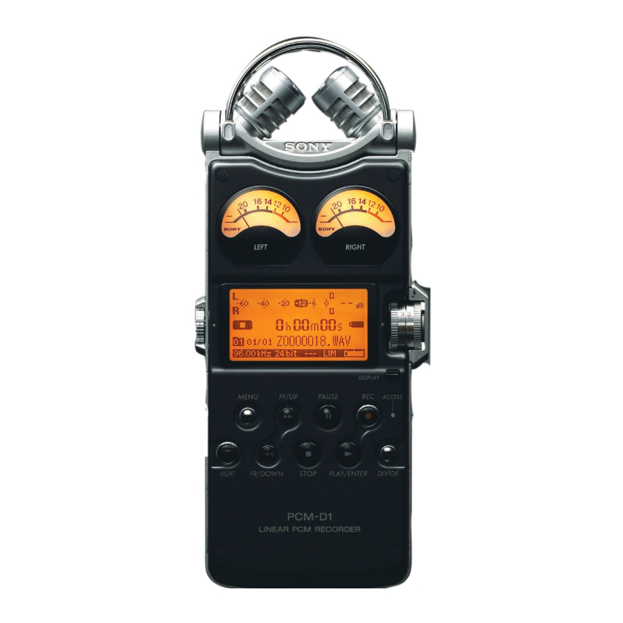
- Page 1 2-664-971-11(1) Linear PCM Recorder Operating Instructions PCM-D1 © 2005 Sony Corporation...
- Page 2 The model number is located at the rear and the serial number is located inside the battery compartment. Record the serial number in the space provided below. Refer to them whenever you call upon your Sony dealer regarding this product. Model No. PCM-D1 Serial No.
- Page 3 Information This equipment has been tested and found to comply with the limits for a Class B digital device, pursuant to Part 15 of the FCC Rules. These limits are designed to provide reasonable protection against harmful interference in a residential installation. This equipment generates, uses, and can radiate radio frequency energy and, if not installed and used in accordance with the...
- Page 4 Use only a cart, stand, tripod, bracket, or table recommended by Sony. Power Source – This appliance should be operated only from the type of power source indicated on the marking label.
- Page 5 This will prevent damage to the appliance due to lightning and powerline surges. Attachments – Do not use attachments not recommended by Sony, as they may cause hazards. Cleaning – Unplug the appliance from the wall outlet before cleaning or polishing it. Do not use liquid cleaners or aerosol cleaners.
-
Page 6: Table Of Contents
Table of Contents Overview Built-in microphones—Pick up sound Electrical circuit—Amplifies sound Exterior—Increase rigidity Identifying parts and controls Getting Started Checking the supplied accessories Step 1: Preparing a power source Step 2: Setting the clock Recording Preparation before recording Recording Monitoring the recording Recording with an external microphone Recording from external equipment Operations after Recording... -
Page 7: Additional Information
Menu Operations Using the menu display Menu items REC MODE (Sampling frequency/quantifying bit number) LIMITER (Preventing distortion) 200Hz HPF (High Pass Filter function) SBM (Super Bit Mapping function) DELETE TRK (Deleting track) DELETE ALL (Deleting all tracks in folder) FORMAT (Initializing memory) LED (Indicator lighting) CLOCK (Date/time setting) MEMORY (Recording/playback memory) -
Page 8: Overview
Overview... - Page 9 PCM-D1 combines these features for recordings that are faithful to the original sound and reproduce even the subtlest of nuances. — A structure free of drive mechanisms — Highly sensitive, built-in condenser microphones — Circuits that process sound with little noise —...
-
Page 10: Built-In Microphones-Pick Up Sound
Overview (continued) Built-in microphones—Pick up sound Side screen Side mesh Microphone unit Top screen Front grill PCM-D1 incorporates electret condenser microphones that were developed for their high sensitivity and low noise. Unlike tape or disc recorders, PCM-D1 has no drive mechanism and is free of motor noise. -
Page 11: Electrical Circuit-Amplifies Sound
Electrical circuit—Amplifies sound Microphone amplifier Dual-shaft, quad-unit volume Sound picked up by the microphones is amplified in the analog circuit, which achieves a frequency response that reaches the high frequencies (Figure 2) and enables the wide dynamic range of PCM-D1. The microphone amplifier provided for each channel is Analog Devices’... -
Page 12: Exterior-Increase Rigidity
Overview (continued) Exterior—Increase rigidity The electrical circuits are protected by a body made of 1 mm thick pure titanium. By means of a pressing process called “drawing,” titanium is shaped into a box to achieve a body rigidity that cannot be obtained through bending or using pressed aluminum. -
Page 14: Identifying Parts And Controls
Overview (continued) Identifying parts and controls Front Right side ... - Page 15 Built-in microphones (page 22) Analog level meters (page 25) Displays left and right volume levels of an audio signal input from microphones in analog values. Display (page 16) VOLUME dial Adjusts the playback volume when turned in +/–...
- Page 16 Overview (continued) Left side Display ...
- Page 17 LINE OUT/optical DIGITAL OUT jack (page 29) LINE IN jack (page 27) MIC ATT (microphone attenuator) switch (page 23) USB connector (page 30) DC IN 6V jack (page 20) HOLD switch When set to “ON,” the buttons on the recorder are locked to prevent accidental operation.
-
Page 18: Getting Started
Getting Started Checking the supplied accessories Windscreen (page 23) • AC power adaptor (6V) • (page 20) To use the wrist strap Attach the wrist strap to the slit for the wrist strap on the right side of the recorder. When an optional headphone, external microphone, audio cable, etc., is connected to the recorder (pages 26 to 29), slip the cord(s) through the wrist strap and tighten the stopper as... -
Page 19: Step 1: Preparing A Power Source
Step 1: Preparing a power source Use the supplied size AA (LR06) nickel metal hydride rechargeable batteries after charging them. Insert the four rechargeable batteries into the battery charger (supplied). Be sure to insert the rechargeable batteries with the and ends in the right position. - Page 20 (supplied) Alkaline batteries 2.0 hours * Approximate values for continuous recording/ playback using Sony size AA (LR06) batteries under a temperature of 20ºC (68ºF). The battery capacity decreases and battery life becomes shorter in low temperatures. To operate with the AC power adaptor Connect the supplied AC power adaptor to the DC IN 6V jack.
-
Page 21: Step 2: Setting The Clock
Step 2: Setting the clock Recorded audio files (tracks) are named using the date and time of the internal clock. By setting the clock before recording, the recording’s date and time will be correctly saved. When the recorder is turned on before the clock has been set, “SET CLOCK”... -
Page 22: Preparation Before Recording
Recording Preparation before recording When you position the recorder, place it so that the microphone points to the sound source. For accurate recording of left and right sources, place the recorder with its front side facing upward (see the illustration below). - Page 23 To switch the microphone input sensitivity Use the MIC ATT switch. Usually set it to the “0” position. When recording loud sounds, set it to the “20” position. To position the recorder using the tripod (not supplied) By attaching the tripod (not supplied), you can adjust angles of the recorder and the microphones more precisely.
-
Page 24: Recording
Recording (continued) Built-in microphones Analog level meters MIC/LINE IN switch Peak level lamps VOLUME dial REC LEVEL L/R dials PAUSE button/ indicator REC button/ indicator PLAY button STOP button Recording To change sampling frequency, quantifying bit number, or the memory and folder for a recording, go to the menu display (page 34). - Page 25 You can check the recording level on both the peak meter of the display and the analog level meters. Adjust the level closer to –12dB into appropriate range that is suitable for your sound source. When checking the level on the peak meter of the display When recording sound that has “quick attack”...
-
Page 26: Monitoring The Recording
Recording (continued) On display of remaining recordable time Remaining recordable time appears in the display when the remaining time becomes 5 minutes or less. Remaining recordable time If an operation other than stop recording, such as fast forward, etc., is done, the remaining recordable time appears in the position where remaining memory volume is usually displayed. -
Page 27: Recording With An External Microphone
Super Audio CD/CD player, etc. Connect the audio output jacks of external equipment to the LINE IN jack of the recorder by using an optional Sony audio cable. Super Audio CD/ CD player... -
Page 28: Operations After Recording
Operations after Recording FF button PAUSE button/ indicator DIVIDE button PLAY button/ indicator STOP button FR button Playing back recorded audio data (tracks) To change the memory and folder to play back, go to the menu display (page 34). Connect optional headphones or earphones to the ... - Page 29 LINE OUT/optical DIGITAL OUT jack of the recorder using an optional Sony audio cable or optical digital cable. PAUSE AV amplifier/player ...
-
Page 30: Dividing A Track
Operations after Recording (continued) Dividing a track You can divide a recorded track. Note that tracks cannot be combined on the recorder after they have been divided. During recording, record pausing, playback, or playback pausing, press the DIVIDE button. The track is divided into two at the point you pressed the button, and “DIVIDING”... - Page 31 System requirements for a computer to be connected to the recorder • IBM PC/AT or compatible – USB port – OS: Windows XP Media Center Edition 2005/ ® Windows XP Media Center Edition 2004/ ® Windows XP Media Center Edition/ ®...
- Page 32 Operations after Recording (continued) On folder and track file structure Once you record audio on the recorder, the 10 folders for saving tracks are automatically created in memory. One “.WAV” file is created for each recording. * Information, such as the order of folders, playback order of audio files, recording date and time, etc., is included.
-
Page 34: Menu Operations
Menu Operations MENU button UP button ENTER button STOP button DOWN button Using the menu display You can change various adjustments and settings using the menu display. Press the MENU button. The menu display appears. The currently selected item and option are in the center of the display in reversed-color characters. -
Page 35: Menu Items
Menu items While the recorder is stopped, all the items in the following chart appear. During recording/ standby for recording/record pausing, only “LIMITER,” “LED,” and “200Hz HPF” appear. During playback/playback pausing, only “DELETE TRK” and “LED” appear. Item Options (Default settings are underlined.) REC MODE You can select the sampling frequency and quantifying bit number for (Sampling frequency/... -
Page 36: 200Hz Hpf (High Pass Filter Function)
Menu Operations (continued) Item Options (Default settings are underlined.) 200Hz HPF Audio under 200 Hz is filtered and is not recorded. This function reduces (High Pass Filter noise caused by the flow of air-conditioning equipment, outdoor air, etc. function) Super Bit Mapping reduces noise when the quantifying bit number is set to (Super Bit Mapping 16 bit in “REC MODE.”... -
Page 37: Clock (Date/Time Setting)
Item Options (Default settings are underlined.) CLOCK You can set the clock. (Date/time setting) For details, refer to page 21. MEMORY You can select the memory where the recorded tracks will be saved and (Recording/playback where the tracks to be played back are saved. memory) BUILT-IN MEMORY STICK... -
Page 38: Using A "Memory Stick Pro (High Speed)" (Not Supplied)
Using a “Memory Stick PRO (High Speed)” (not supplied) ACCESS indicator Memory Stick slot “Memory Stick PRO (High Speed)” * Cover of Memory Stick slot * When you use “Memory Stick PRO Duo (High Speed),” be sure to use the Memory Stick Duo adaptor. - Page 39 4 GB are checked on the recorder, but this does not guarantee operations of all “Memory Stick PRO (High Speed).” Because the Sony “Memory Stick PRO (High Speed)” is the only “Memory Stick” that is operationally tested on the recorder, “Memory Stick PRO (High Speed)”...
-
Page 40: Maintenance
Maintenance On noise • Noise may be heard when the recorder is placed near an AC power source, a fluorescent lamp or a mobile phone during recording or playback. • Noise may be recorded when an object, such as your finger, etc., rubs or scratches the recorder during recording. -
Page 41: Troubleshooting
(Note that initializing will delete all data in the memory.) Read through the symptoms and solutions on pages 41 to 43 and messages on pages 44 and 45 to check your recorder. If the problem persists, consult with qualified Sony personnel (see the warranty for contact information). Symptom... - Page 42 Troubleshooting (continued) Symptom Cause/Solution You cannot erase a • The write-protect switch on the inserted “Memory Stick PRO (High Speed)” track. is set to “LOCK.” Release the lock. • When you use a Windows computer, the track or the folder containing the track is set to “Read-only”...
- Page 43 Symptom Cause/Solution A character in a folder or • The recorder cannot support or display some special characters and track name is displayed symbols that are entered on a computer using Windows Explorer or Mac in unreadable Desktop. characters. “ACCESSING MEMORY” •...
-
Page 44: Error Messages
Troubleshooting (continued) Error messages Message Meaning/Solution SET CLOCK The clock is not set. Set it before operating the recorder (page 21). 16 bit ONLY The “SBM” item can be set to “ON” only when the quantifying bit number is set to 16 bit. Change the quantifying bit number to 16 bit on “REC MODE” in the menu display, and then set “SBM”... - Page 45 A system error has occurred. Remove the batteries or the AC power adaptor to turn off the recorder completely, and then turn on the recorder again. If this message appears again, consult with qualified Sony personnel (see the warranty for contact information).
-
Page 46: Specifications
Specifications Recording media Built-in flash memory 4 GB, “Memory Stick PRO (High Speed)” (not supplied), Stereo recording Maximum recording time Refer to “Maximum recordable time” on page 49. Quantization 16-bit linear, 24-bit linear Frequency range (Input from the LINE IN jack when recording/playing back) (0 to –2 dB) Fs 22.05 kHz: 20 to 10,000 Hz Fs 44.10 kHz: 20 to 20,000 Hz... - Page 47 General Power requirements DC IN 6V (AC 120V, 60 Hz) Four size AA (LR06) nickel metal hydride rechargeable batteries NH-AA (supplied) Four size AA (LR06) alkaline batteries (not supplied) Power consumption 2.1W Dimensions Approx. 72.0 × 193.0 × 32.7 mm ×...
-
Page 48: File Specifications
File specifications Once you record audio in the built-in memory or a “Memory Stick PRO (High Speed),” the 10 folders for saving tracks are automatically created in each memory. One “.WAV” file is created for each recording. For details about the folders and track file structure, refer to page 32. - Page 49 Maximum recordable time (Approximate) The total maximum recordable time (approximate) of all the folders is as follows. Built-in flash memory (4 GB) Sampling frequency/ Maximum quantifying bit number recordable time * 22.05 kHz 16 bit 13 hrs 10 min. 44.10 kHz 16 bit 6 hrs 35 min.
-
Page 50: Index
Index Symbols (headphone) jack ... 26, 28 FF/UP button ... 21, 29 FR/DOWN button ... 21, 29 PAUSE button/indicator . 25, 29 PLAY/ENTER button/indicator 21, 28 REC button/indicator ...24 STOP button ... 25, 29 200Hz HPF ...36 ACCESS indicator ... - Page 51 “Memory Stick PRO (High Speed)” ...38 Maintenance ...40 Maximum recordable time ...49 MEMORY ...37 Memory Stick slot ...38 MENU button ...34 Menu display ...34 MIC/LINE IN switch ... 15, 24 MIC ATT switch ...23 MIC jack ...27 Monitoring the recording ...26 Peak level lamps ...25 Peak meter ...25 Playing back ...28...
- Page 52 Printed in Japan...