Table of Contents
Advertisement
Quick Links
Sep. 2017
Table of Contents
Cautionary Notes ..............................................................2
Specifications .....................................................................3
Location of Controls .........................................................4
Location of Controls Parts List........................................5
Exploded View ..................................................................6
Exploded View Parts List.................................................7
Disassembly Procedure ....................................................7
Plain View ..........................................................................8
Plain View Parts List.........................................................8
Block Diagram/Wiring Diagram..................................10
Parts List ...........................................................................12
Copyright © 2017 Roland Corporation
All rights reserved. No part of this publication may be reproduced in any form without the written permission
of Roland Corporation.
Verifying the Version......................................................14
Data Backup and Restore Operations ..........................14
Performing a Factory Reset............................................14
Updating the System ......................................................14
Test Mode .........................................................................15
Circuit Board (Main Board) ...........................................18
Circuit Diagram (Main Board: 1/3)..............................20
Circuit Diagram (Main Board: 2/3)..............................22
Circuit Diagram (Main Board: 3/3)..............................24
Circuit Board (Panel, Jack, Pedal Board) .....................26
Circuit Diagram (Panel, Jack, Pedal Board) ................28
17057129E0
SERVICE NOTES
Issued by RJA
AD-10
CC-KWS
Advertisement
Table of Contents

Related Manuals for Roland AD-10


Summary of Contents for Roland AD-10
-
Page 1: Table Of Contents
Circuit Board (Panel, Jack, Pedal Board) .....26 Parts List ................12 Circuit Diagram (Panel, Jack, Pedal Board) ....28 Copyright © 2017 Roland Corporation All rights reserved. No part of this publication may be reproduced in any form without the written permission of Roland Corporation. -
Page 2: Cautionary Notes
• Because reissuance is restricted. • Because the part is made to order (at current market price). • Because it is carried in electronic data on the Roland web site. • Because it is a package or an accessory irrelevant to the function maintenance of the main body. -
Page 3: Specifications
ANTI-FEEDBACK (REDUCTION, NOTCHx2) * Printed matters will not be supplied after the end of the production. Then, download the electronic file from the Roland web site. Phrase Loop * In the interest of product improvement, the specifications and/or appearance of 80 sec this unit are subject to change without prior notice. -
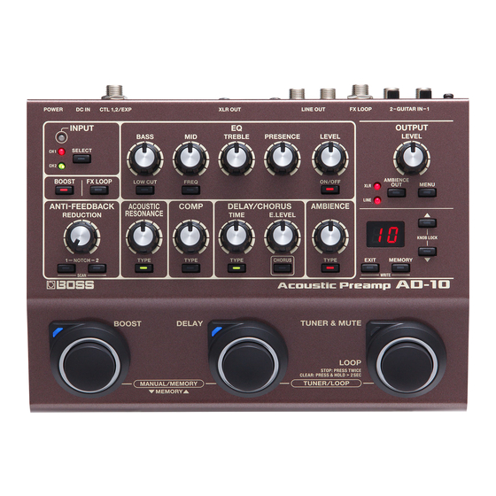
Page 4: Location Of Controls
Sep. 2017 AD-10 Location of Controls fig.panel.eps... -
Page 5: Location Of Controls Parts List
Sep. 2017 AD-10 Location of Controls Parts List Part Code Part Name Description Q’ty 5100049857 OSRGHC3132A 5100024412 LED SPACER LED3X6.5 05015956 BL L-7104SRT (F5229820R0) 5100037402 LED SPACER LEDS-7.5S 05015967 L-7104SGT 5100037402 LED SPACER LEDS-7.5S 5100001453 ROTARY POTENTIOMETER RD901F-40-125F-B50K-0CD 03344934 R-KNOB... -
Page 6: Exploded View
Sep. 2017 AD-10 Exploded View fig.bunkai-e.eps * Apply adhesive (#40122445). -
Page 7: Exploded View Parts List
Sep. 2017 AD-10 Exploded View Parts List Part Code Part Name Description Q’ty 03344934 R-KNOB (75D522N0R0) 5100050211 SWITCH PEDAL RING 5100049509 SWITCH PEDAL 5100050359 SWITCH PEDAL FOOT 5100050360 PEDAL SPRING 5100049510 SWITCH PEDAL ESCUTCHEON 5100049511 SWITCH PEDAL LED LENS 5100050548 THERMAL SHRINKAGE TUBE 15X10.0... -
Page 8: Plain View
Sep. 2017 AD-10 Plain View fig.heimen.eps View 1 View 2 View 3 View 4 Plain View Parts List View 1 Part Code Part Name Description Q’ty 40012534 SCREW 3X6 BINDING TAPTITE S FE BZC 5100036736 SCREW 2.9X9 BINDING TAPTITE B SERRATE BZC... - Page 9 Sep. 2017 AD-10...
-
Page 10: Block Diagram/Wiring Diagram
Sep. 2017 AD-10 Block Diagram/Wiring Diagram fig.block.eps@L MAIN BOARD A+3.3 A+3.3 AVCC AVCC IC10 2SK880 NJM2115 MUTE DTr NJM4580 Pre-Em GUITAR 1 buffer A+3.3 IC18 De-Em CODEC GTR1 NJM2115 (AK4556) NJM4580 AFAD MUTE DTr Multiplexer De-Em (GAIN ctl) A+3.3 AVCC SDDA1 A+3.3... - Page 11 Sep. 2017 AD-10 fig.block.eps@R XLR OUT L GND LIFT XLR OUT R L/PHONES R/MONO JACK BOARD OUTR DET JK202 SEND VR201 VR202 JK201 CTL/EXP CTL-TIP/RING CTL DET PVCC BATTERY MONITOR Circuit AIN2 Multiplexer STEREO/MON Panel SW Multiplexer Foot SW × 2...
-
Page 12: Parts List
• Reissuance is restricted. only listed parts for replacement. • It is carried in electronic data on the Roland web site. • It is supplied as an assembled part • The part is made to order (at current market price). - Page 13 Sep. 2017 AD-10 SCREWS 40017934 SCREW M3X6 PAN MACHINE W/SW+PW(L) FE ZC 40342712 SCREW M3X6 PAN MACHINE W/SW+SMALL PW 5100008243 SCREW 2.6X5 (H5019430R0) BINDING TAPTITE P FEZC 5100036736 SCREW 2.9X9 BINDING TAPTITE B SERRATE BZC 40011301 SCREW 3X6 BINDING TAPTITE P FE BZC...
-
Page 14: Verifying The Version
Start the MIDI sequence program on the computer, and set the MIDI 0 through 9: The number corresponding to the lighting button indicates output device to the AD-10, and send the SysEx data which has been the value of the second decimal place. -
Page 15: Test Mode
Sep. 2017 AD-10 * Never switch off the power or detach the plug of the AC adaptor while the update Quitting the Test Mode is in progress. Turn off the power. When 10 buttons all light up and ok is displayed on the 7-segment LED display, the update has finished. - Page 16 Sep. 2017 AD-10 2. Version Check Press The LEDs shown in the figure light up green. This verifies the version. fig.led-green.eps The display of the 7-segment LED display and the lighting of the buttons indicate the version as shown in the figure below.
- Page 17 Sep. 2017 AD-10 Sh Expression Pedal Check SA Noise check * Before the unit enters this test item, connect the expression pedal to the CTL Verify that the STEREO/MONO switch is set at MONO. 1,2/EXP jack. Set the both INPUT SENS knobs and all knobs on the top cover to the minimum.
-
Page 18: Circuit Board (Main Board)
Sep. 2017 AD-10 Circuit Board (Main Board) fig.b-main-1.eps... - Page 19 Sep. 2017 AD-10 fig.b-main-2.eps...
-
Page 20: Circuit Diagram (Main Board: 1/3)
Sep. 2017 AD-10 Circuit Diagram (Main Board: 1/3) fig.d-main-1.eps@L AD-10 MAIN BOARD (Power) TP77 TP76 PVCC AVCC DC IN KM02020ABM2P QS8J4TR QS8J4TR 2SC4738-GR(TE85L.F) 11.2V 11.8V (PSA-**S) 8.55 - 9.5V 2.2k 0.47uF 330k FS-7 DC JACK HOLDER FS-7 DC JACK HOLDER 100uF 0.1uF... - Page 21 Sep. 2017 AD-10 fig.d-main-1.eps@R D+1.2 2012 47uF 6.3V D+3.3 2012 TP80 100uF 1SS387 A+3.3 NJM2882F33-TE1 2012 TP110 VOUT CTRL N-BP C338 10uF 0.01uF 0.1uF 0.1uF...
-
Page 22: Circuit Diagram (Main Board: 2/3)
Sep. 2017 AD-10 Circuit Diagram (Main Board: 2/3) fig.d-main-2.eps@L A+3.3 C120 0.1uF AD-10 MAIN BOARD (Analog) fc1=1.48kHz YCOM fc2=8.61kHz TP179 TP178 Gain=15.3dB A+3.3 gain0=-8.55dB gain1=+1.76dB XCOM gain2=+11.38dB R147 MPX1-B gain3=+20.00dB MPX1-A AVCC 1SS362FV SN74LV4052APWR 10uF 10uF TP135 270k 0.5% 6.3V 6.3V... - Page 23 Sep. 2017 AD-10 fig.d-main-2.eps@R TP159 gain=+8.63dB 3300pF 5.6k fc1=1.48kHz 0.5% R168 fc2=8.61kHz Gain=15.3dB TP37 TP50 0.5% TP47 C122 C159 R332 C157 47uF 22uF R334 47pF 1608 0.5% IC10 C164 NJM4580V-TE1-#Z#ZB R340 R120 UnPop 100k 100k DAREF-XLR TP129 CT3-05M-EP XLR OUT L 4.7k...
-
Page 24: Circuit Diagram (Main Board: 3/3)
Sep. 2017 AD-10 Circuit Diagram (Main Board: 3/3) fig.d-main-3.eps@L D+1.2 AD-10 MAIN BOARD (Digital) D+3.3 C193 R210 IC21 IC21 TC7WU04FU TC7WU04FU R231 C222 CKUDL-M 0.1uF D+1.2 R218 IC21 IC21 TC7WU04FU TC7WU04FU C202 DSX321G 16.9344MHZ C255 C256 10pF 10pF XSWD-PWR CTL-DET D+3.3... - Page 25 Sep. 2017 AD-10 fig.d-main-3.eps@R ED-M(15:0) R188 R189 EA-M(14:0) R229 slave EA-M(14) EA-M(13) R212 EA-M(14) EA-M(10) R213 EA-M(13) EA-M(12) R215 EA-M(12) EA-M(11) D+3.3 C259 EA-M(9) C260 10uF EA-M(8) 10uF D+3.3 1608 EA-M(7) 1608 EA-M(6) C217 0.1uF EA-M(5) C241 0.1uF C208 0.1uF...
-
Page 26: Circuit Board (Panel, Jack, Pedal Board)
Sep. 2017 AD-10 Circuit Board (Panel, Jack, Pedal Board) fig.b-panel.eps... - Page 27 Sep. 2017 AD-10...
-
Page 28: Circuit Diagram (Panel, Jack, Pedal Board)
Sep. 2017 AD-10 Circuit Diagram (Panel, Jack, Pedal Board) fig.d-panel.eps@L AD-10 PANEL SHEET D+3.3 (EQ) [BASS] PANEL BOARD RD901F-40-12 RD901F-40-12 RD901F-40-12 JACK BOARD TP155 D+3.3 TP157 EXP/CTL [ANTI-F JKD+3.3 JK201 HTJ-064-22HSPP RV09BDF-40E1 RV09BDF-40E1 RV09BDF-40E1 JKGND R114 TP161 TP156 Q101 DTC114TUAT106... - Page 29 D+3.3 PD+3.3 TP162 TP163 TP164 TP165 TP166 _SCLR TP167 TP168 TP169 TP170 TP151 PD+3.3 TC74VHC595FK CN101 TP147 PDGND AD-10 RIBBON CABLE R113 12P L=40x6x6 P=2.0 R110 SW101 SKPFACA010 [BOOST] TP148 TP133 PEDAL-SW R111 SW102 SKPFACA010 [DELAY] TP149 R112 SW103 SKPFACA010...