Table of Contents
Advertisement
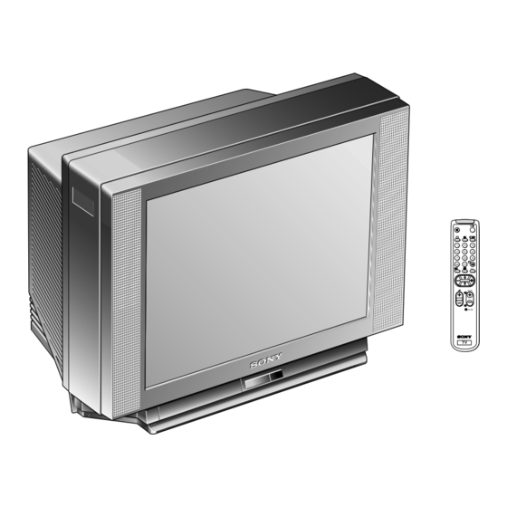
SERVICE MANUAL
MODEL
COMMANDER
KV-29FX11A
KV-29FX11B
KV-29FX11D
KV-29FX11E
M I C R O F I L M
DEST
Chassis NO.
RM-886
Italian
SCC-K05S-A
RM-886
French
SCC-K01U-A
RM-886
AEP
SCC-K07U-A
RM-886
Spanish
SCC-K06U-A
SELF-DIAGNOSTIC FUNCTION
MODEL
COMMANDER
KV-29FX11K
KV-29FX11R
KV-29FX11U
TRINITRON
1
BE-3D
CHASSIS
DEST
CHASSIS NO.
RM-886
OIRT
SCC-K20K-A
RM-886
OIRT
SCC-K20L-A
RM-886
UK
SCC-K04Q-A
/
MENU
PROGR
RM-883
COLOR TV
®
®
Advertisement
Table of Contents

Related Manuals for Sony TRINITRON KV-29FX11A


Summary of Contents for Sony TRINITRON KV-29FX11A
- Page 1 SERVICE MANUAL MODEL COMMANDER KV-29FX11A RM-886 Italian KV-29FX11B RM-886 French KV-29FX11D RM-886 KV-29FX11E RM-886 Spanish M I C R O F I L M MODEL DEST CHASSIS NO. KV-29FX11K SCC-K05S-A KV-29FX11R SCC-K01U-A KV-29FX11U SCC-K07U-A SCC-K06U-A SELF-DIAGNOSTIC FUNCTION BE-3D CHASSIS COMMANDER DEST CHASSIS NO.
-
Page 2: Input/Output Terminals
ITEM MODEL Television System Italian B/G/H French B/G/H, D/K, L, I B/G/H Spanish B/G/H, D/K OIRT B/G/H, D/K MODEL 29FX11A Power Consumption 89.3 W [PICTURE TUBE] Super Trinitron Approx. 72cm (29 inches) (Approx. 68 cm picture measured diagonally) 110 degree deflection Input/Output Terminals [REAR] 21-pin Euro connector (CENELEC standard). - Page 3 Model Name KV-29FX11A KV-29FX11B Item Pal Comb Woofer Box Scart 1 Scart 2 Front in (3) Scart 4 Projector AKB in 16:9 mode Norm B/G/H Norm I Norm D/K Norm AUS Norm L Norm SAT Norm M Teletext Nicam Stereo Language Preset Italian WARNING...
- Page 4 21 pin connector ( Pin No _ Red input _ Video input Connected Pin No Signal Ground Ground Y (S signal) input 1V+/- 3dB 75 ohm, positive Sync 0.3V -3/+10dB C (S signal) input 0.3V+/- 3dB 75 ohm, positive Sync Signal Signal level Audio output B...
-
Page 5: Table Of Contents
EXPLOSÈES ET LES LISTES DE PIECES SONT D’UNE IMPORTANCE CRITIQUE POUR LA SÈCURITÈ DU FONCTIONNEMENT, NE LES REMPLACER QUE PAR DES COMPSANTS SONY DONT LE NUMÈRO DE PIÈCE EST INDIQUÈ DANS LE PRÈSENT MANUEL OU DANS DES SUPPLÈMENTS PUBLIÈS PAR SONY. - Page 20 2-1. REAR COVER REMOVAL 4 Rear Cover 2-3-1. SERVICE POSITION (1) 2 Insert into heatsink 1 Snap off from main bracket SECTION 2 DISASSEMBLY 2-2. CHASSIS ASSY REMOVAL 3 2 Screws (BTVTP 4x16) 2 6 Screws (BTVTP 4x16) 1 1 Screw 4x10 2-3-2.
- Page 21 2-4. WIRE DRESSING 2-5. A BOARD REMOVAL A Board 1 Remove CN301 before removing A board 2-6. A EXTENSION BOARD A board BE-3D Extension Board...
-
Page 22: Picture Tube Removal
2-7. PICTURE TUBE REMOVAL 9 Spring Extension Speaker Two screws 10 C board 12 Neck assy 14 Four Screws Anode cap 15 Picture tube • REMOVAL OF ANODE-CAP Note : Short circuit the anode of the picture tube and the anode cap to the metal chassis, CRT shield or carbon paint on the CRT, after removing the anode. - Page 23 REMOVAL AND REPLACEMENT OF THE MAIN-BRACKET BOTTOM PLATES. (1) REMOVING THE PLATES In the event of servicing being required to the solder side of the D Board printed circuit, the bottom plates fitted to the main chassis bracket require to be removed. This is performed by cutting the gates with a sharp wire cutter at the locations shown and indicated by arrows.
-
Page 24: Beam Landing
KV-29FX11 • When complete readjustment is necessary or a new picture tube is installed, carry out the following adjustments. • Unless there are specific instructions to the contrary, carry out these adjustments with the rated power supply. • Unless there are specific instructions to the contrary, set the controls and switches to the following settings : Contrast ... - Page 25 3-2. CONVERGENCE Preparation: • Before starting this adjustment, adjust the focus, horizontal size and vertical size. • Minimize the Brightness setting. • Input a dot pattern from the pattern generator. Horizontal and vertical static convergence Center dot V.STAT Magnet H.STAT RV702 Screen [Moving horizontally], adjust the H.STAT control so that the...
- Page 26 KV-29FX11 • Operation of the BMC (Hexapole) magnet. • The respective dot position resulting from moving each magnet interact, so be sure to perform adjustment whilst tracking. Use the H.STAT VR to adjust the Red, Green and Blue dots so that they coincide at the centre of the screen (by moving the dots in the horizontal direction).
-
Page 27: Tv Operation
Screen corner convergence. • If you are unable to adjust the corner convergence properly, correct them with the use of permalloy assemblies. a-d: screen-corner convergence defect Install the permalloy assembly for the area that needs correcting. Permalloy. 3-3. WHITE BALANCE G2 Setting Switch the TV set into AV mode [apply a cross-hatch signal]. -
Page 28: Electrical Adjustments
KV-29FX11 4-1. ELECTRICAL ADJUSTMENTS Service adjustments to this model can be performed using the supplied Remote Commander RM-886. HOW TO ENTER INTO SERVICE MODE Turn on the main power switch and enter into the stand-by mode. Press the following sequence of buttons on the Remote Commander. - Page 29 AGC ON/OFF Constant gain CDB FM prescale FMP Zwei mono-st WHI Zwei st-mono WLO Zwei mono-bi WMH Zwei bi-mono WLO Time Zwei WML Fawct limit Fawct soll init FAW Fawer tol Nicam Err Max CCT Nicam Err Min Nicam Prescale NIP Time Nicam Carrier mute CRM Audio clock ACO...
- Page 30 KV-29FX11 SYSTEM B/G, D/K, I & L I.F ADJUSTMENT Input an off air signal of between 60-100dBuV / 75 ohm terminated, via the tuner socket. Enter into the ‘IF Adjustment’ service mode [i.e ‘TT59’] to fix the I.F frequency to 39.9MHz. Enter into the service mode and select ‘Current TV status’.
-
Page 31: Test Mode 2
4-2. TEST MODE 2: Is available by pressing ‘TEST’ button twice, OSD ‘TT’ appears. The functions described below are available by pressing the two numbers. To release the Test mode 2, press 0 twice, or switch the TV into stand-by mode. Note : ‘TT’... - Page 32 KV-29FX11 DSP Bypass D/K Nicam Disable Diagnostics OFF Diagnostics ON No function Lumisponder Curve 1 Lumisponder Curve 2 Jungle Select (CXA2000 or CXA2076) Text H Position adjust Picture reset MSP BG filter enabled (h/w required) Sound reset MSP BG filter disabled (h/w required) Wide set-up (Wide screen models only) No function Velocity mod ON...
-
Page 33: Be-3D Self Diagnostic Software
4-3. BE-3D SELF DIAGNOSTIC SOFTWARE The identification of errors within the BE-3D chassis is triggered in one of two ways :- 1: Busy busy or 2: Device failure to respond to IIC. In the event of one of these situations arising the software will first try to release the bus if busy [Failure to do so will report with continuous flashing LED] and then communicate with each device in turn to establish if a device is faulty. -
Page 34: Block Diagrams
SECTION 5 DIAGRAMS BLOCK DIAGRAM (1) D901 IC500 D810 STBY 5V Q900 SWITCH V OUT +200V RECT Q501 200V D504 D505 RESP +135V IC900 SIRCS +15V INFRARED RECEIVER D507 D803 SWITCH SWITCH V BOOST CN902 Q503 Q502 +15V D503 ROT COIL +15V RECT V OUT - -15V... - Page 40 WAVEFORMS D BOARD 1.2K Vp-p (H) 2.6 Vp-p (H) 1.0 Vp-p (H) WAVEFORMS C BOARD 110 Vp-p (H) WAVEFORMS A BOARD 3.5 Vp-p (H) 3.0 Vp-p (H) 1.0 Vp-p (H) 1.4 Vp-p (H) SECAM NTSC 1.5 Vp-p (H) 0.9 Vp-p (H) 56.0 Vp-p (V) 13 Vp-p (H) 56 Vp-p (V)
- Page 41 IC BLOCK DIAGRAMS A BOARD IC301 CXA2076Q-TL H SYNC V SYNC GATE SHARP D PIC 50/60 ID TRAN VIDEO NESS TRAP CONT INTER- KILLER LACE YS/YM PAL/ NTSC COLOR I REF AXIS &AXIS A BOARD IC202 MSP3410D SBUS Interface I2C Interface DEMODULATOR IDENT SCART Switching Facilities...
- Page 42 5-4 SEMICONDUCTORS CXA2040Q-T4 (TOP VIEW) L4941BV TEA7605 LM393P M5216P TDA2822M PC393C ( TOP VIEW ) LM2940CT-5.0 LM2940CT LM2940T-9.0 MCT7809CT NJM78M09FA PC2405HF MSP3410D-PS-B4-T STR-S6709 ( TOP VIEW ) PST593C-MMP-4P STV9379 ( TOP VIEW ) TDA4665T-T SBX1981-51 ( TOP VIEW ) SDA5273M-CP-GEG TDA7264 ( TOP VIEW ) SE135N...
- Page 43 TLP721(D4-) AU-01Z-V1 EG-1Z-V1 EGP20G EL1Z EM1-V1 ERB44-06TP1 EU-1-V1 EU2A EU2-V1 2SC2785-HFE ANODE 2SA1837 BAS216 DTZ6.8C DTZ9.1 DTZ33B ANODE 2SC2688-LK D4SB60L 2SC4793 FMS-3FU 2SC4927-01 FML-G12S ERA38-06TP1 GP08D MTZJ-3.6A HSS83TD MTZJ-3.9B RGP02 MTZJ-5.1B RGP10GPKG23 MTZJ-5.6B RGP15GPKG23 MTZJ-6.2BMTZJ-6.8C RU3YX-V1 MTJ-7.5C RU4AM-T3 MTZJ-9.1 RU4DS MTZJ-T-77-9.1A MTZJ-10 CATHODE...
-
Page 44: Exploded Views
NOTE : • Items with no part number and no description are not stocked because they are seldom required for routine service. • The construction parts of an assembled part are indi- cated with a collation number in the remarks column. 6-1. -
Page 45: Vm Board
KV-29FX11 6-2. PICTURE TUBE REF. NO. PART.NO DESCRIPTION X-4200-386-1 BEZNET ASSY 4-045-250-01 DAMPER 4-204-190-11 DOOR (KV-29FX11A/29FX11D/29FX11R) 4-204-190-01 DOOR (KV-29FX11B/29FX11E/29FX11K/29FX11U) 4-202-555-01 SHAFT DOOR 4-042-192-11 CATCHER, PUSH 4-204-195-01 WINDOW ORNAMENTAL 4-204-194-01 BUTTON, POWER 4-202-964-11 SPRING 4-204-196-01 GUIDE LIGHT 4-204-201-01 BRACKET, SPEAKER 1-505-952-11 SPEAKER 4-039-356-01 SCREW (3X12),(+) BV TAPPING £... -
Page 46: Electrical Parts List
REF. NO. PART.NO DESCRIPTION *A-1632-783-A A BOARD, COMPLETE ***************** *A-1632-782-A A BOARD, COMPLETE ***************** *A-1632-769-A A BOARD, COMPLETE ***************** *A-1632-784-A A BOARD, COMPLETE ***************** *A-1632-785-A A BOARD, COMPLETE ***************** *A-1632-786-A A BOARD, COMPLETE ***************** *A-1632-781-A A BOARD, COMPLETE ***************** 1-750-797-11 SOCKET, PLCC <... - Page 47 KV-29FX11 REF. NO. PART.NO DESCRIPTION C225 1-163-133-00 CERAMIC CHIP 470PF C226 1-126-967-11 ELECT 47MF C227 1-164-232-11 CERAMIC CHIP 0.01MF C228 1-126-967-11 ELECT 47MF C229 1-164-232-11 CERAMIC CHIP 0.01MF C230 1-216-295-00 SHORT C233 1-126-967-11 ELECT 47MF C238 1-126-967-11 ELECT 47MF C239 1-163-141-00 CERAMIC CHIP 0.001MF C242 1-164-489-91 CERAMIC CHIP 0.22MF...
- Page 48 The components identified by shading and marked are critical for safety Replace only with the part number specified. REF. NO. PART.NO DESCRIPTION C356 1-164-232-11 CERAMIC CHIP 0.01MF C357 1-163-133-00 CERAMIC CHIP 470PF C358 1-164-005-11 CERAMIC CHIP 0.47MF C359 1-163-231-11 CERAMIC CHIP 15PF C360 1-163-231-11 CERAMIC CHIP 15PF C370...
- Page 49 KV-29FX11 REF. NO. PART.NO DESCRIPTION Q111 8-729-216-22 TRANSISTOR 2SA1162-G Q112 8-729-620-06 TRANSISTOR 2SC3052-EF Q120 8-729-620-06 TRANSISTOR 2SC3052-EF Q121 8-729-620-06 TRANSISTOR 2SC3052-EF Q122 8-729-620-06 TRANSISTOR 2SC3052-EF Q124 8-729-620-06 TRANSISTOR 2SC3052-EF Q130 8-729-216-22 TRANSISTOR 2SA1162-G Q140 8-729-620-06 TRANSISTOR 2SC3052-EF Q141 8-729-216-22 TRANSISTOR 2SA1162-G Q201 8-729-620-06 TRANSISTOR 2SC3052-EF Q202...
- Page 50 The components identified by shading and marked are critical for safety Replace only with the part number specified. REF. NO. PART.NO DESCRIPTION 1-216-081-00 RES,CHIP 1-216-025-00 RES,CHIP 1-216-025-00 RES,CHIP 1-216-025-00 RES,CHIP 1-216-033-00 RES,CHIP 1-216-033-00 RES,CHIP 1-216-033-00 RES,CHIP R101 1-216-061-00 RES,CHIP 3.3K 5% R102 1-216-025-00 RES,CHIP R103...
- Page 51 KV-29FX11 REF. NO. PART.NO DESCRIPTION R256 1-216-025-00 RES,CHIP R257 1-216-013-00 RES,CHIP R258 1-216-049-00 RES,CHIP R265 1-216-065-00 RES,CHIP 4.7K 5% R266 1-216-073-71 RES,CHIP R267 1-216-073-71 RES,CHIP R270 1-216-022-00 RES,CHIP R271 1-216-022-00 RES,CHIP R272 1-216-022-00 RES,CHIP R273 1-216-022-00 RES,CHIP R280 1-216-049-00 RES,CHIP R281 1-216-089-00 RES,CHIP R282...
- Page 52 The components identified by shading and marked are critical for safety Replace only with the part number specified. REF. NO. PART.NO DESCRIPTION R1027 1-216-025-00 RES,CHIP R1028 1-216-025-00 RES,CHIP < TUNER > TU101 1-693-338-11 TUNER/VIF (AEP) (KV-29FX11A/29FX11D/29FX11E/ KV-29FX11K/29FX11R) 1-693-340-11 TUNER/VIF (FR) 1-693-339-11 TUNER/VIF (UK) <...
- Page 53 KV-29FX11 IF ( KV-29FX11B REF. NO. PART.NO DESCRIPTION A-1652-036-A IF BOARD, COMPLETE (KV-29FX11B) ****************** < CAPACITOR > 1-162-638-11 CERAMIC CHIP 1MF 1-164-337-11 CERAMIC CHIP 2.2MF 1-104-957-11 ELECT 47MF 1-135-259-11 TANTAL. CHIP 10MF 1-164-004-11 CERAMIC CHIP 0.1MF 1-164-005-11 CERAMIC CHIP 0.47MF 1-164-232-11 CERAMIC CHIP 0.01MF 1-164-004-11 CERAMIC CHIP 0.1MF 1-164-004-11 CERAMIC CHIP 0.1MF...
- Page 54 The components identified by shading and marked are critical for safety Replace only with the part number specified. REF. NO. PART.NO DESCRIPTION *A-1638-113-A C BOARD, COMPLETE ***************** < CAPACITOR > C702 1-128-551-11 ELECT 22MF C703 1-126-967-11 ELECT 47MF C704 1-102-945-00 CERAMIC C705 1-102-945-00 CERAMIC C706...
-
Page 55: D5 Board
KV-29FX11 REF. NO. PART.NO DESCRIPTION < SPARK GAP > SG701 1-517-712-31 GAP, SPARK SG702 1-517-712-31 GAP, SPARK SG703 1-517-712-31 GAP, SPARK SG704 1-519-421-11 GAP, DISCHARGE ********************************************************************* *A-1640-307-A D5 BOARD, COMPLETE ****************** < CAPACITOR > C2801 1-102-244-00 CERAMIC 220PF C2804 1-136-165-00 FILM 0.1MF C2805 1-164-070-11 CERAMIC... - Page 56 The components identified by shading and marked are critical for safety Replace only with the part number specified. REF. NO. PART.NO DESCRIPTION R2821 1-247-807-31 CARBON R2823 1-535-465-11 LEAD, JUMPER (5.0MM) R2824 1-249-425-11 CARBON 4.7K 5% R2825 1-249-417-11 CARBON R2826 1-249-417-11 CARBON R2827 1-249-441-11 CARBON 100K 5%...
- Page 57 KV-29FX11 REF. NO. PART.NO DESCRIPTION C630 1-111-097-11 ELECT 0.0022F C631 1-126-965-11 ELECT 22MF C632 1-104-666-11 ELECT 220MF C633 £ 1-107-563-11 FILM 0.1MF C635 £ 1-107-563-11 FILM 0.1MF C636 £ 1-113-920-11 CERAMIC 0.0022MF C638 1-136-203-11 FILM 0.01MF C640 1-106-220-00 MYLAR 0.1MF C641 £...
- Page 58 The components identified by shading and marked are critical for safety Replace only with the part number specified. REF. NO. PART.NO DESCRIPTION D503 8-719-979-85 DIODE EGP20G D504 8-719-991-33 DIODE 1SS133T-77 D505 8-719-982-03 DIODE MTZJ-3.6A D506 8-719-991-33 DIODE 1SS133T-77 D507 8-719-109-85 DIODE RD5.1ES-B2 D510 8-719-924-13 DIODE MTZJ-T-77-22B D570...
- Page 59 KV-29FX11 REF. NO. PART.NO DESCRIPTION L609 1-412-533-21 INDUCTOR 47UH L610 1-535-465-11 LEAD, JUMPER (5.0MM) L611 1-412-527-11 INDUCTOR 15UH L612 1-412-522-41 INDUCTOR 5.6UH L613 1-412-522-41 INDUCTOR 5.6UH L615 1-412-529-11 INDUCTOR 22UH L616 1-412-533-21 INDUCTOR 47UH L801 1-459-111-00 INDUCTOR L802 1-459-104-00 COIL, WITH CORE L803 1-535-465-11 LEAD, JUMPER (5.0MM) L805...
- Page 60 The components identified by shading and marked are critical for safety Replace only with the part number specified. REF. NO. PART.NO DESCRIPTION R627 1-216-347-11 METAL OXIDE 0.68 5% R628 1-249-415-11 CARBON R629 £ 1-260-135-11 CARBON R630 £ 1-218-265-11 METAL 8.2M 5% R631 £...
- Page 61 KV-29FX11 D VM REF. NO. PART.NO DESCRIPTION < RELAY > RY600 £ 1-755-018-11 RELAY < SWITCH > S601 £ 1-571-433-21 SWITCH, PUSH (AC POWER) S801 1-572-707-11 SWITCH, LEVER S900 1-692-979-21 SWITCH, TACTILE S901 1-692-979-21 SWITCH, TACTILE S902 1-692-979-21 SWITCH, TACTILE <...
-
Page 62: K5 Board
The components identified by shading and marked are critical for safety Replace only with the part number specified. REF. NO. PART.NO DESCRIPTION < RESISTOR > R1701 1-249-397-11 CARBON R1702 1-247-807-31 CARBON R1703 1-249-416-11 CARBON R1704 1-247-807-31 CARBON R1706 1-247-815-91 CARBON R1707 1-249-411-11 CARBON R1708... -
Page 63: Picture Tube
KV-29FX11 REF. NO. PART.NO DESCRIPTION MISCELLANEOUS ************** £ 1-406-807-11 COIL, DEMAGNETIZATION 1-452-032-00 MAGNET, DISC: 10MM Ø 1-452-094-00 MAGNET, ROTATABLE DISK: 15MM Ø £ 1-453-269-11 TRANSFORMER ASSY, FLYBACK (NA-4511/U2B4) 1-505-937-11 SPEAKER (10CM) 1-505-952-11 SPEAKER £ 1-571-433-21 SWITCH, PUSH (AC POWER) 1-693-338-11 TUNER/VIF (AEP) 1-693-340-11 TUNER/VIF (FR) 1-693-339-11 TUNER/VIF (UK) £... - Page 64 KV-29X5 English Sony Corporation 98BP7173-1 Sony UK Printed in U.K. © 1998.2 Service Promotions Dept. 9-974-967-01...