
Related Manuals for Lochinvar EcoShield SHW35-245CE


Summary of Contents for Lochinvar EcoShield SHW35-245CE
- Page 1 EcoShield™ Gas Fired Condensing Water Heaters Installation, Commissioning, & Maintenance instructions MODELS SHW35-245CE SHW46-325CE SHW61-325CE SHW86-410CE SHW116-410CE SHW146-410CE Installation Manual_EcoShield_October 2018...
-
Page 3: Table Of Contents
Table of Contents INTRODUCTION ....................................................... 5 SAFETY GUIDELINES ..................................................... 6 GENERAL DESCRIPTION OF SAFETY SYMBOLS USED ..........................................6 WHAT TO DO IF YOU SMELL GAS ..................................................7 PRINCIPLE PARTS ....................................................8 TECHNICAL DATA ....................................................10 DIMENSIONS AND CLEARANCE ................................................ 11 DIMENSIONS ........................................................ - Page 4 17.9 OTHER CHECKS ........................................................59 18.0 USER CONTROL INTERFACE SETTINGS ............................................61 18.1 TIME AND DATE ........................................................61 18.2 USER ADJUSTABLE PARAMETERS SCREEN ..............................................61 18.3 INSTALLER ADJUSTABLE PARAMETERS SCREEN ............................................62 18.4 PASTEURISATION FUNCTION (USING NIGHT SET BACK FACILITY) ......................................63 18.5 NIGHT SETBACK SCREEN ....................................................
-
Page 5: Introduction
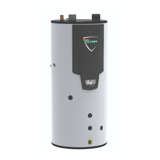
INTRODUCTION The Lochinvar EcoShield™ range is a floor standing direct gas-fired condensing storage water heater. The equipment comprises a stainless steel mesh radial burner assembly; a heat exchanger that permits fully condensing operation, a vitreous enamel lined steel storage vessel, a Stainless Steel circulating pump and interconnecting pipework between the storage vessel and heat exchanger. -
Page 6: Safety Guidelines
SAFETY GUIDELINES READ AND UNDERSTAND THE INSTRUCTIONS Read and fully understand all instructions before attempting to operate maintain or install the unit. Keep these instructions near the water heater for quick reference. This equipment must be installed by a competent person, registered with the H.S.E. approved body. All installations must conform to the relevant Gas Safety and Building Regulations. -
Page 7: What To Do If You Smell Gas
Do not re-enter the building until it is safe to do so Lochinvar Limited is not liable for any damage caused by inaccurately following these installation instructions. Only original parts may be used when carrying out any repair or service work. -
Page 8: Principle Parts
PUMP RELAY RLY2610 VENTURI GASKET GKT2443 GKT2444 MAGNESIUM ANODE WTR2500 HEAT EXCHANGER C/W GASKETS/FITTINGS LL200030P LL200031P LL200032P LL200033P LL200034P LL200035P RECOMMEND LOCHINVAR FIT THIS ITEM LOW VOLTAGE CONNECTION BOARD LL100167623 AIR SHROUD GASKET GKT2080 PRINCIPLE PARTS-USE IN CONJUNCTION WITH 3.1.2... - Page 9 XPLODED VIEW DRAWINGS...
-
Page 10: Technical Data
TECHNICAL DATA SHW35- SHW46- SHW61- SHW86- SHW116- SHW146- Model Number 245CE 325CE 325CE 410CE 410CE 410CE GENERAL DATA Product I.D Number CE0063 Catergory(ies) II2H3B/P Countries of Destination GB/IE Input (gross) 36.6 61.5 83.5 116.9 146.5 Input (net) 33.3 39.6 55.4 75.2 105.3 Output (P... -
Page 11: Dimensions And Clearance
DIMENSIONS AND CLEARANCE DIMENSIONS HEIGHT WIDTH T&P VALVE COLD FEED HOT OUTLET MODEL TANK VOLUME SHW35-245 1530 1610 1610 SHW46-325 1920 1117 2005 2005 SHW61-325 1920 1126 2005 2005 SHW86-410 1920 2020 2020 SHW116-410 1920 2020 2020 SHW146-410 1920 2020 2020 DIMENSIONAL DRAWING ECOSHIELD™... -
Page 12: Clearances
CLEARANCES The location chosen for the equipment must permit the provision for a satisfactory flue system and, where necessary, an adequate air supply. The location must also provide adequate space for servicing and air circulation around each unit. This includes any electrical trunking laid across the floor and to the appliance. -
Page 13: General Requirements
GENERAL REQUIREMENTS The Lochinvar EcoShield™ condensing water heater has been designed to operate trouble free for many years. These instructions should be followed closely to obtain the maximum usage and efficiency of the equipment. READ AND UNDERSTAND THE INSTRUCTIONS Read and fully understand all instructions before attempting to operate maintain or install the unit. -
Page 14: Water Quality
The Water Resources Act requires that trade effluent is discharged to municipal sewers between pH 6.5 and 10.0. If it is determined that these levels cannot be achieved, an in-line condensate neutralisation kit is available from Lochinvar Limited. This unit is capable of neutralising 4000... -
Page 15: Gas Supply
GAS SUPPLY The Lochinvar EcoShield™ range is suitable for use on second and third family gasses 2H - G20 - 20mbar and 3P - G31 - 37mbar. Details relating to Natural Gas (2H) appear below; for details relating to Propane (3P) please refer to Section 16.0 LPG FUEL. -
Page 16: Flue System
Aluminium flue pipe must not be used on this appliance as it may lead to premature failure of the heat exchanger and will invalidate the warranty. Before installation of any flue system read the installation manual carefully for both the appliance and flue system to be used. Information on the flue system Supplied by Lochinvar can be found within this manual. - Page 17 Model Number SHW35-245CE SHW46-325CE SHW61-325CE SHW86-410CE SHW116-410CE SHW146-410CE FLUE DATA TYPE B Nominal flue diameter (d Nominal flue diameter (d 80 +/-0.3 100 +/-0.3 outside Nominal flue diameter (d 81 +/-0.6 101+/-0.6 inside Nominal flue diameter (L 50 +20/ -2 50 +20/ -2 insert Maximum flue gas temp.
-
Page 18: Flue Discharge
10.2 FLUE DISCHARGE The flue system must ensure safe and efficient operation of the equipment to which it is attached, protect the combustion process from wind effects and disperse the products of combustion to open external air. The flue must terminate in a freely exposed position and be so situated as to prevent the products of combustion entering any opening in a building. -
Page 19: Flue System General Requirements
APPROVED FLUE SYSTEM For Concentric and Twin pipe flue systems only the Lochinvar supplied M&G flue system must be used The approved flue system is not suitable for use external to the building. If external routes cannot be avoided, a flue system manufacturer should be consulted to supply a suitable alternative. -
Page 20: Room Sealed (Type C) Flue Assembly
10.9 ROOM SEALED (TYPE C) FLUE ASSEMBLY Before fitting the flue system for either type C13 Horizontal or C53 Vertical Concentric flue the flue transition kit should be installed to the top of the heater as per 10.9.3 and 10.9.7 SHW35-245,SHW46-325,SHW61-325 SHW86-410,SHW116-410,SHW146-410 ECOSHIELD™... - Page 21 ITEM DESCRIPTION CONCENTRIC ADAPTER EXTENSION ELBOW FLUE CONNECTION DETAILS SHW35-245CE - SHW61-325CE MODEL “X” DIMENSION SHW35-245 NG CE 115mm SHW46-325 NG CE 195mm SHW61-325 NG CE No cut required EXTENSION LENGTH SHW35-245 CE - SHW61-325 CE To install the flue connection to the SHW35-245CE - SHW61-325CE water heaters the following procedure should be followed: Insert the air intake transition into the intake connection reducer and tighten the worm drive clip.
-
Page 22: C13 Concentric Horizontal Flue Systems
To install the flue connection to the SHW86-410 CE – SHW146-410 CE water heaters the following procedure should be followed: Insert the air intake transition into the intake connection reducer and tighten the worm drive clip. Fit 100mm elbow (Item 3 in 10.9.7) to cut end of extension. To the side (intake) connection of the concentric adaptor (Item 1 in 10.9.7), fit the other end of the 100mm dia. -
Page 23: Horizontal Flue Terminal Installation
10.11 HORIZONTAL FLUE TERMINAL INSTALLATION When the Water Heater is installed as a Type C (Horizontal concentric) appliance, the flue system should be installed as follows: Determine the location of the flue terminal, taking into account minimum distances as detailed in 10.3.1 and the relevant British Standards. -
Page 24: C33 Concentric Vertical Flue Systems
10.13 C CONCENTRIC VERTICAL FLUE SYSTEMS Flue system specifications MANUFACTURER MUELINK AND GROL (M&G) TEMPERATURE CLASS T120 FLUE GAS MATERIAL PP Each concentric Vertical flue kit includes the items shown in the tables below Item No SHVF003 CONCENTRIC VERTICAL FLUE ASSEMBLY MODELS SHW35-245,SHW46-325,SHW61-325 COMPONENTS INCLUDED... - Page 25 When inserting the roof terminal do not support or turn the terminal using the cap. Ensure the terminal is vertical using a spirit level. Fit the support bracket around the terminal and secure using appropriate fixings. Do not tighten the support bracket Install the remainder of the flue system working progressively away from the water heater supporting the pipes as necessary.
- Page 26 GENERAL CONCENTRIC FLUE SYSTEM INSTALLATION GUIDELINES The information in this section is for General guidance only and may not fully represent the installation on site Do not drill and screw into flue system...
- Page 27 Max distance between brackets...
-
Page 30: Ccommon 43 Ccommonommon Vented Flue Systems In Multi Floor Buildings
10.15 C COMMON VENTED FLUE SYSTEMS IN MULTI FLOOR BUILDINGS In C43 systems water heaters are fitted on common air inlet and flue gas outlet (either concentric or parallel) systems in multiple floor buildings. Only use a C43 venting system when the common duct is a natural draught chimney. The common duct is part of the building, not a part of the system. -
Page 31: C 53 (Twin Pipe) Flue Systems
CONCENTRIC HORIZONTAL TERMINAL Ø80/125mm PP (NO WALL PLATES) LV305039 HORIZONTAL AIR INLET Ø100mm ALU M28925 TERMINAL WALL PLATES (PAIR) When installing EcoShield™ on a C twin pipe flue system, the Lochinvar Twin pipe flue starter assembly must be fitted first. - Page 32 When installing the water heater as a Type C53 appliance, it should be noted that the terminals must not be installed on opposite sides of the building. If the flue temperature sensor is not fitted, the flue gas temperature may exceed the maximum temperature rating of the flue and can lead to severe personal injury, death or substantial property damage.
- Page 33 GENERAL TWIN-PIPE INSTALLATION GUIDELINES The information in this section is for General guidance only and may not fully represent the installation on site...
-
Page 35: Flue Terminal Guarding
10.17 FLUE TERMINAL GUARDING If a horizontal flue terminal is to be fitted less than 2 metres from ground level or in a location where it can be touched from a window, door or balcony, a terminal guard must be fitted. The terminal guard is constructed from plastic-coated mild steel and is suitable for use on condensing appliances only. -
Page 36: Type B (Conventional Flue With Fan Assistance)
10.18 TYPE B (CONVENTIONAL FLUE WITH FAN ASSISTANCE) Item No SHCF003 CONVENTIONAL FLUE ASSEMBLY MODELS SHW35-245,SHW46-325,SHW61-325 COMPONENTS REQUIRED TO START INSTALLATION Item No. Description Included M75256 AIR INLET TRANSITION Ø80mm ALU M73039 AIR INLET GRILLE Ø80mm ALU M85279 SAMPLING POINT Ø80mm PP Item No SHCF004 CONVENTIONAL FLUE ASSEMBLY MODELS SHW86-410,SHW116-410,SHW146-410... -
Page 37: Ccertified 63 Ccertifiedertified Flue Systems
10.19 C CERTIFIED FLUE SYSTEMS In general, Water heaters are certified with their own purpose supplied Concentric or Twin Pipe flue systems, C certified appliances allow the installer to use other flue systems when installing the Water heater however, they must be of a suitable minimum standard as per Table below. CE string flue gas material... -
Page 38: Air Supply
11.0 AIR SUPPLY The following information is based on single water heater installations only. If more than one water heater is being used, BS6644 should be consulted to calculate the necessary requirements. 11.1 COMBUSTION VENTILATION When used as a Type C appliance, provided sufficient clearance is provided, ventilation for combustion is not necessary as the combustion air is ducted directly from outside. -
Page 39: Water Connections
OPEN VENTED SYSTEM ARRANGEMENT The Lochinvar EcoShield™ can be used in an open vented arrangement provided that a vent pipe in accordance with CP 342, BS6644 or BS6700 as appropriate is fitted. The minimum static head requirement for an open vented system is 1.0 bar. -
Page 40: Unvented System Arrangement
It is the law that unvented hot water systems be installed by an approved installer. If the Lochinvar EcoShield™ is to be used in an unvented arrangement, the system should follow the guidance given in BS6700 and must comply with the Building Regulations 1992: Part G3, in England and Wales,P5 in Northern Ireland and P3 in Scotland. A kit of components that have been suitably sized for the unvented operation of the appliance is available from Lochinvar Limited. - Page 41 TEMPERATURE AND PRESSURE RELIEF VALVE A temperature and pressure relief valve is factory fitted as part of the unvented water system kit. This valve has a lift pressure of 7 bar and a lift temperature of 90°C. This should be checked for transit damage prior to filling the water heater. The storage vessel relief valve connection should not be used for any other purpose.
-
Page 42: Electrical Supply
The WH19/WH21 unvented kit supplied with the EcoShield™ water heater includes an expansion vessel, this should be checked by the installer to ensure there is sufficient spare capacity available for the Hot water secondary system volume. If not an additional correctly sized expansion vessel should be installed, additional expansion vessels are available from Lochinvar Ltd. Unvented kit Expansion vessel EcoShield™... -
Page 43: External Controls
13.2 EXTERNAL CONTROLS EcoShield™ is compatible with the following control and safety systems: Auxiliary safety system proving switch (e.g. fan dilution system proving switch) In addition to this, EcoShield™ can give the following signals: Volt-free “burner on” (runtime) signal Volt-free “lock-out”... -
Page 44: Low Voltage Connector Strip
13.4 LOW VOLTAGE CONNECTOR STRIP LOW VOLTAGE CONNECTION STRIP CONNECTION NOTES EXTERNAL These connections should be used to enable the heater via a BMS on/off input. CONTROL SPARE EXTERNAL This can be used to prevent the unit firing until a fan dilution system or other external control has proved CONTROL 24V COM RELAY Can be used to supply an enable signal to an external control such as a fan dilution system... -
Page 45: Electrical Connections
13.5 ELECTRICAL CONNECTIONS Cable routing to the High Voltage and Low Voltage Connection Strips can be achieved by removing the appropriate knockouts on the top panel of the heater. All connections should be secured using an appropriate cord anchorage. One cord anchor is supplied with the heater for securing the mains supply to the unit. -
Page 46: Wiring Diagram
13.8 WIRING DIAGRAM VALVE X5-4 R/BK OUTLET SENSOR X5-12 OUTLET SENSOR X5-6 PK/BK INLET SENSOR LWCO W/BK X5-5 FLUE SENSOR X5-13 FLUE SENSOR CONNECTION X5-14 X5-14 BOARD CN3-1 X5-2 CN3-2 CN3-3 X5-10 CN3-4 X5-11 O/BK ALARM HEX SWITCH CONTACTS CN2-5 X4-14 86-146 MODEL ONLY... -
Page 47: Ladder Diagram
13.9 LADDER DIAGRAM LADDER DIAGRAM... -
Page 48: User Control Interface
14.0 USER CONTROL INTERFACE 14.1 GENERAL The EcoShield™ user control interface gives information on set-up, system status and diagnostic data. 14.2 USER CONTROL INTERFACE PANEL USER CONTROL INTERFACE PANEL... -
Page 49: Sequence Of Operation
14.3 SEQUENCE OF OPERATION Operation Display 1. Upon call for heat the control turns on the integrated pump. 2. The control connects 230 VAC to the fan. The fan does not run at this time. If the unit is equipped with a low water cut-off, it must be closed before the control powers up the fan. - Page 50 5. If the control does not detect flame by the end of the trial for ignition, the control performs a 10 second post-purge. On the SHW35 CE to SHW116 CE models, the control will perform another pre-purge and try to light the burner again. If the burner does not light after 4 trials, the control will lockout for 1 hour and then try another set of 4 trials.
-
Page 51: Commissioning And Testing
15.0 COMMISSIONING AND TESTING 15.1 ELECTRICAL INSTALLATION Notes on the requirements for electrical installation are provided in Section 13.0: ELECTRICAL SUPPLY. A schematic drawing of the control circuit is shown in Figure 13.8 15.2 GAS INSTALLATION For design see Section 9.0: GAS SUPPLY. See Section 3.0: PRINCIPAL PARTS for details on the position of the gas connection. 15.3 WATER CONNECTIONS For design see Section 12.0: WATER CONNECTIONS... -
Page 52: Temperature Adjustment Procedure
Once the unit has reached temperature and shut down, check that the flame has extinguished. GAS PRESSURE ADJUSTMENT AND COMBUSTION CHECKS The Lochinvar EcoShield™ series are supplied with a pre-set gas/air ratio inlet assembly. This must not be tampered with. Any attempt to adjust the gas valve or venturi will invalidate the warranty. -
Page 53: Lpg Fuel
The conversion MUST be carried out by a competent person certified for work on LPG fuel. In the event of any seal or gasket being broken it is essential that the seal or gasket be replaced. Contact Lochinvar limited for replacement seals and gaskets. - Page 54 SHW35-245CE – SHW86-410CE Remove the front access cover from the unit. Remove the impulse tube and wiring plug from the gas valve. Remove the four screws securing the gas valve to the venturi (Figure 16.2.3). Locate the propane orifice disk from the conversion kit bag. Verify that the stamping on the orifice disk is correct for the water heater (see Table 16.2.1).
- Page 55 CONVERSION PROCEDURE SHW116-410CE SHW146-410CE Remove the front access covers from the unit. Remove the gas valve and manifold from the unit via the unions on each end (Figure 16.2.7). Remove the three screws mounting the injector plate on the air shroud (Figure 16.2.7 Remove the four screws securing the manifold adapter to the injector plate taking care not to damage the O-ring.
-
Page 56: Lpg Commissioning And Testing
10.5% 0.5% SHW61-325CE <100 ppm 10.5% 0.5% SHW86-410CE <100 ppm 10.5% 0.5% SHW116-410CE <100 ppm 10.5% 0.5% SHW146-410CE <100 ppm LPG COMBUSTION FIGURES If the combustion figures are not within the range specified, contact Lochinvar Technical support for further guidance. -
Page 57: Maintenance
17.0 MAINTENANCE 17.1 GENERAL Keep appliance area clear and free from combustible materials and flammable vapours and liquids. A competent person should check and ensure that the flue, its support and terminal, the ventilation to the boiler house, safety valve, drain, pressure gauge etc. -
Page 58: Cleaning The Heat Exchanger
A kit of components to aid with cleaning the heat exchanger is available from Lochinvar Limited. For models SHW35- 245 use part number KIT30062 for SHW46-325CE– SHW116-410CE use part number KIT30063, for model SHW146- 410CE use part number KIT30064. -
Page 59: Sacrificial Anodes: Inspection And Replacement
17.7 SACRIFICIAL ANODES: INSPECTION AND REPLACEMENT If the Correx non-sacrificial anode protection system is used, there is no requirement to check the condition of the anodes. The tank is protected against corrosion by means of two sacrificial anodes fitted in the front of the storage vessel. The rate at which the anodes are eroded is dependent on the quality of the water;... - Page 60 RELIEF VALVE At least once a year, the temperature and pressure relief valve and safety valve should be checked to ensure that they operate correctly. To check the valves, the manual override levers should be operated several times. The valves should seat properly and operate freely. If water does not flow, drain the heater, remove the inoperative valve and inspect for obstructions or corrosion.
-
Page 61: User Control Interface Settings
Replacement assemblies are available and include all spares required to replace the heat exchanger. Lochinvar can provide a quote to carry out the replacement work if required. Replacement heat exchanger assembly item numbers are shown below contact Lochinvar customer service for prices and availability... -
Page 62: Installer Adjustable Parameters Screen
18.3 INSTALLER ADJUSTABLE PARAMETERS SCREEN To access the Installer Adjustable Parameters screen press and hold the ENTER and DOWN buttons simultaneously for 5 seconds. Once pressed the installer code P01 should be shown in the lower digits. Once you have cycled through all of the parameters, the new values will be set. -
Page 63: Pasteurisation Function (Using Night Set Back Facility)
18.4 PASTEURISATION FUNCTION (USING NIGHT SET BACK FACILITY) THE PROCEDURE FOR A WEEKLY HIGH TEMPERATURE (70 C) PASTEURISATION IS AS FOLLOWS: Access the installer menu (Down & Enter for 5 seconds). Set parameter p02 to 15°C (this is a deduction from the pasteurisation temperature and can be reduced to 10°C if a 65°C storage temperature is required instead of 60°C). - Page 64 THE PROCEDURE FOR A DAILY PASTEURISATION WHEN SUPPLYING DOMESTIC HOT WATER AT LESS THAN Systems must always comply with the requirements of L8, running the water heaters at low temperatures may encourage the growth of legionella bacteria. Access the installer menu (Down & Enter for 5 seconds). ...
-
Page 65: Night Setback Screen
18.5 NIGHT SETBACK SCREEN To access the Night Setback screen press and hold the UP and DOWN buttons simultaneously for 5 seconds. Once pressed the trigger type, On/OFF, should be shown in the upper digits of the display. Use the UP and DOWN buttons to display the desired trigger type, On or OFF and then press ENTER to make selection. The trigger number will then appear, On1 or OFF1 depending on previous selection, in the upper digits on the display. -
Page 66: Troubleshooting
Check wiring connection at flue sensor Check resistance of flue sensor with table 19.1 Gas supply pressure problem Refer to Section 3 Technical data Gas/air mixture problem Contact Lochinvar ltd Noisy Operation Dirty/damaged burner Remove and inspect/clean burner Low water flow... -
Page 67: Error Codes
Check sensor resistance correct see table 19.1 Check wiring connections to the fuse on the heat exchanger Thermal Fuse open Check continuity if open contact Lochinvar ltd Check ancillary operating correctly Ancillary proving switch Check wiring to switch Check for blockages in condense trap/pipework... - Page 68 Error Codes Description Corrective Action Inspect spark electrode and associated wiring for damage and correct connection, replace if required Check for correct electrical earthing Flame signal lost 4 times Check incoming gas supply pressure is correct refer to section 9.0 gas supply Verify the plastic hose from the gas valve to the air inlet is connected and undamaged...
- Page 69 Error Codes Description Corrective Action Check wiring to sensor, make sure all is correctly connected and One or both outlet sensors is open or undamaged shorted Check resistance of sensors with table , replace sensor if required. 19.1 Inlet sensor is open Check wiring to sensor, make sure all is correctly connected and undamaged Inlet sensor is shorted...
-
Page 70: Erp Specification Data Sheet
20.0 ErP SPECIFICATION DATA SHEET SHW35- SHW46- SHW61- SHW86- SHW116- SHW146- Water Heater Type: Manufacturer Lochinvar Limited Load Profile Energy Efficiency Daily Electricity Qelec 0.333 0.382 0.541 0.517 0.531 0.552 Consumption Daily Fuel Qfuel 31.398 32.893 56.18 58.399 59.236 57.952... - Page 71 NOTES...